EP0436577B1 - Procede et installation de mesure pour la determination de grandeurs mecaniques - Google Patents
Procede et installation de mesure pour la determination de grandeurs mecaniques Download PDFInfo
- Publication number
- EP0436577B1 EP0436577B1 EP89910424A EP89910424A EP0436577B1 EP 0436577 B1 EP0436577 B1 EP 0436577B1 EP 89910424 A EP89910424 A EP 89910424A EP 89910424 A EP89910424 A EP 89910424A EP 0436577 B1 EP0436577 B1 EP 0436577B1
- Authority
- EP
- European Patent Office
- Prior art keywords
- abutment
- accordance
- movement
- measuring device
- counter
- Prior art date
- Legal status (The legal status is an assumption and is not a legal conclusion. Google has not performed a legal analysis and makes no representation as to the accuracy of the status listed.)
- Expired - Lifetime
Links
- 238000000034 method Methods 0.000 title claims description 24
- 230000008569 process Effects 0.000 title claims description 14
- 238000011326 mechanical measurement Methods 0.000 title claims 5
- 238000005259 measurement Methods 0.000 claims abstract description 19
- 230000010355 oscillation Effects 0.000 claims abstract description 6
- 238000013016 damping Methods 0.000 claims description 38
- 230000008859 change Effects 0.000 claims description 13
- 230000001105 regulatory effect Effects 0.000 claims description 6
- 230000001276 controlling effect Effects 0.000 claims description 5
- 230000003534 oscillatory effect Effects 0.000 claims description 5
- 230000005489 elastic deformation Effects 0.000 claims description 2
- 230000009466 transformation Effects 0.000 claims description 2
- 230000002401 inhibitory effect Effects 0.000 claims 1
- 230000001960 triggered effect Effects 0.000 abstract 1
- 238000006073 displacement reaction Methods 0.000 description 10
- 230000001965 increasing effect Effects 0.000 description 8
- 238000013017 mechanical damping Methods 0.000 description 6
- 230000001052 transient effect Effects 0.000 description 6
- 238000010586 diagram Methods 0.000 description 4
- 238000005303 weighing Methods 0.000 description 4
- 230000009471 action Effects 0.000 description 3
- 238000011161 development Methods 0.000 description 3
- 238000012360 testing method Methods 0.000 description 3
- 238000006243 chemical reaction Methods 0.000 description 2
- 230000000694 effects Effects 0.000 description 2
- 238000011156 evaluation Methods 0.000 description 2
- 238000012545 processing Methods 0.000 description 2
- 230000004044 response Effects 0.000 description 2
- 208000036829 Device dislocation Diseases 0.000 description 1
- 238000013459 approach Methods 0.000 description 1
- 230000005540 biological transmission Effects 0.000 description 1
- 230000001914 calming effect Effects 0.000 description 1
- 238000010276 construction Methods 0.000 description 1
- 230000001934 delay Effects 0.000 description 1
- 238000001914 filtration Methods 0.000 description 1
- 230000001939 inductive effect Effects 0.000 description 1
- 238000005381 potential energy Methods 0.000 description 1
- 230000036316 preload Effects 0.000 description 1
- 238000005070 sampling Methods 0.000 description 1
- 230000002123 temporal effect Effects 0.000 description 1
Images


Classifications
-
- G—PHYSICS
- G01—MEASURING; TESTING
- G01G—WEIGHING
- G01G23/00—Auxiliary devices for weighing apparatus
- G01G23/06—Means for damping oscillations, e.g. of weigh beams
- G01G23/10—Means for damping oscillations, e.g. of weigh beams by electric or magnetic means
-
- G—PHYSICS
- G01—MEASURING; TESTING
- G01G—WEIGHING
- G01G3/00—Weighing apparatus characterised by the use of elastically-deformable members, e.g. spring balances
Definitions
- the invention relates to a method for determining mechanical measured quantities, in which a measured quantity transducer elastically deforms under the influence of the measured quantity to be determined and thereby transforms the mechanical measured quantity into a proportional electrical measurement signal, and in which the transducer abutment after a change in the measured quantity or the action of a disturbance quantity is forced to a sensibly controlled counter movement relative to the inertial system.
- the invention further relates to a corresponding measuring device for determining mechanical measured variables with a transducer which deforms elastically under the action of a mechanical measured variable and which converts the measured variable into a proportional electrical signal, and with an electrically controllable servomotor which moves the transducer abutment after a sudden change in the Measured variable or the action of a disturbance variable to meaningful counter movements relative to the inertial system.
- Measuring devices for the determination of mechanical measurands such as forces, weights, torques, voltages, pressures or distances, often contain an elastic transducer that deforms elastically and proportionally under the influence of the measurand to be determined.
- Such transducers can be resistive, capacitive or inductive in nature, with the deformation or deflection of the measuring spring body then leads to the conversion of the mechanical measured variable into a - mostly proportional - electrical measuring signal. Due to its elastic deformation, the transducer stores a potential energy that has to be applied by the measurement object. As a rule, this is subject to mass and thus has, for example, an inertial mass, an moment of inertia or an inertia.
- this unit then forms an oscillatory system which, after an abrupt change in the input variable, undergoes a settling process that is more or less long depending on the internal damping of the system before it reaches its steady state of equilibrium comes to rest.
- the period of the settling cycles is - non-linear - proportional to the inertia and the resilience of the elastic transducer.
- critical damping Until the so-called critical damping is reached, up to which overshoots occur via the new stationary equilibrium position, the period of the natural oscillation increases in the same direction and the duration of the transient process shortens in the opposite direction with the natural damping of the measuring system. If this is greater than the critical damping, the system no longer swings beyond the stationary end position, but slowly approaches it asymptotically.
- the simplest way to obtain a measured value more quickly from a mechanically weakly damped elastic measuring system is to filter the electrical output signal of the transducer analog or digital. While the analog filtering can only lead to comparatively small improvements by setting an upper limit frequency below the natural frequency, a digital filter works by selectively suppressing the system natural frequencies in general. significantly more successful. Nevertheless, with such a filter, very exact measured values can only be obtained with great effort if the measuring system has already carried out several oscillations around the stationary end position.
- the state of the art also includes intelligent measurement data processing, in which the analog electrical output signals of elastic measurement transducers are sampled at short intervals and converted into digital values. If the most important system parameters, such as spring stiffness, inherent damping and mass of the moving parts of the measuring system, are known to a sufficient extent, the new steady state of equilibrium, and thus the one corresponding to the measured variable, can be determined by intelligent evaluation of the first measured data after a change in the measured variable Estimate the measured value. In addition, the pre-calculated dynamic course of the transient process can be continuously compared with the actual sensed course, and the accuracy of the estimated measured value can thus be continuously increased until it lies within predetermined limits.
- the object of the present invention is to provide a method and a measuring device with which it is possible to greatly shorten the settling times of such measuring systems with elastic transducers.
- this task is solved in that the transducer abutment is forced to a sensibly controlled counter-movement relative to the inertial system (center of the earth) after a sudden change in the measured variable.
- the task of describing a corresponding device is achieved in that an electrically controllable servomotor is provided which moves the abutment of the elastic measurement variable sensor after a relief of the measured variable and in that the device has an output signal from the sensor processing circuit for controlling the servo motor comprises.
- the oscillatory system it is sufficient for the oscillatory system if it has a low passive internal damping in order to achieve extremely short transient damping.
- This is possible through the use of a servomotor, which is controlled by the Output signal of the elastic transducer, which moves the transducer abutment after a change in the input variable in such a way that any vibration energy is withdrawn from the measuring system in the shortest possible time.
- the servomotor succeeds in bringing the transducer abutment to such displacements in any short time that the absolute size (amount) is the same, but exactly opposite in their respective directions to the displacements with which the load introduction point of a conventional, i.e. reacts to sudden changes in the measured quantity with an immobile transducer bearing.
- the elastic energy to be stored in the steady state of equilibrium after the introduction of a non-zero measured variable into the elastic sensor, the measuring spring, is therefore no longer applied by the test object itself, but by the servomotor. Since the measuring system then opposes the measured variable with an equally large reaction component at all times, it appears completely unyielding to the outside, i.e.
- the servomotor can be controlled directly by the electrical output signal of the measuring spring, since this signal provides information about the instantaneous deflection of the elastic sensor at any time without delay. Deflection is understood to mean the relative movement between the load introduction point and the sensor abutment.
- the counter-displacement of the transducer abutment is therefore continued until the moment at which dynamic deflections of the measuring spring have completely subsided.
- this is not absolutely necessary for the functioning of the system according to the invention. A single movement of the abutment against the deflection of the measuring spring leads to considerably reduced settling times.
- a position sensor is therefore to be provided which detects the displacements of the transducer abutment and enables its position control.
- the position control or regulation described above is therefore based on a system analysis of the transducer abutment replaced by a speed control.
- the manipulated variable or command variable required to control the speed servomotor, the deflection speed of the transducer can be obtained in the simplest case by differentiating its electrical output signal.
- the control of the servomotor for moving the transducer abutment is carried out by an intelligent circuit with a microcomputer.
- the known, most important system parameters of the respective measuring device can be used for intelligent control or regulation of the abutment movement.
- the optimal countermovement of the transducer abutment in the sense of the shortest possible settling time can be calculated in advance from the time course of the first measured values detected by the transducer after a sudden change in the measured variable and can be carried out using the full drive power of the servomotor used.
- the course of the counter movement calculated as the best possible can be continuously corrected and further optimized by sampling the sensor output signal influenced by this movement.
- there is of course the high cost of intelligent control or regulation which can, however, be justified for exceptionally critical applications.
- the natural damping of a measuring device increases in proportion to the increase in the natural frequency. If the mass of the moving parts of the servomotor and the transducer abutment is small compared to the total mass composed of the masses of the test object and the moving parts on the load introduction side of the transducer, then the one from a series with Damping device resulting from the servomotor lying likewise and increased to the same extent by the device according to the invention.
- Such a mechanical, series-acting damping device makes little sense here, however, since it would still be fully loaded by the measured variable and all dead loads even after the measuring device had fully settled, and the servomotor would consequently have to constantly move the input of the damping device in order to calmly exit it hold.
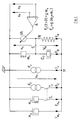
- Fig. 1 the structure of a measuring device according to the invention is shown using the example of an electromechanical elastic weighing device.
- the measuring transducer 1 works here according to the principle of strain gauges, in which the mechanical deformation of a spring body, which is proportional to the deflection, is converted into an electrical output signal by resistive elements 6, which are generally arranged in a bridge circuit. Without the elements shown in the upper area of FIG. 4, the position sensor 5, the control circuit 8 and the servomotor 9 with gear 4, this was a conventional strain gauge balance with a fixed, that is to say stationary with respect to the inertial system pickup abutment S.
- the output signal from the bridge circuit from the strain gauges 6 mounted on the measuring spring has changed from u o to a value u m , is electrically amplified via the amplifier 7 and converted by the electronics 10 into a digital measured value displayed by the unit 11.
- the weight 2 to be measured forms together with the dead load the weighing pan and moving parts of the measuring spring 1 in unity with the resilience of the spring an oscillatory system. For this reason, the new stationary equilibrium position of the measuring device will only set after a sudden, possibly impulsive change in the measured variable after a transient process which is more or less long depending on the natural damping of the arrangement. In the normal case, strain gauge measuring devices are extremely difficult to effect because of their small spring travel and are mechanically dampened with regard to the measuring accuracy.
- the pickup abutment S is no longer stationary, but can be moved by the servomotor 9, possibly via a gear 4.
- the actuation of the servo motor 9 assumes the amplifier element 8, whose inputs the amplified through 7 output signal u m of the transducer bridge, and u a of the relocation, if necessary, the electrical output signal s A of the Auftechnikwiderlagers S detecting the position sensor 5 are.
- s m (t) is zero at all times, ie the flexibility of the measuring system also appears to be zero.
- the block diagram according to FIG. 2 shows such a system in which a servo motor VA acting as a speed actuator moves the sensor abutment S at a speed v a .
- m x here is the inertial mass of the goods to be weighed, F E its weight, m o the inertial mass of the moving dead load of the measuring system (load pan, etc.), and F o is finally the weight of this dead load.
- the switches T1 and T2 are open until the sample is placed on the weighing pan, then closed, so that the weight F E and the inertial mass m x then act on the measuring system.
- a damping element D P is arranged, which on the one hand includes the natural damping (eg air), and on the other hand possibly includes other artificial damping devices attached to the measuring system.
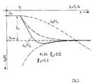
- FIG. 3 shows the transient response of a measuring device according to the invention in comparison to that of a weakly damped, conventional elastic measuring system.
- the measured variable is changed abruptly, as a result of which the measuring spring is deflected by the value ⁇ o in the steady state of equilibrium.
- the measuring spring leads according to the invention equipped with a system only vibrations to T o / 5 reduced period T oB whose ripple is already less than 0.89% of S o.
- the measuring system behaves in the same way as the arrangement according to FIG. 2, if 4, the damping device D P from FIG. 2 acting parallel to the measuring spring is replaced by a series-acting damper D s .
- a simple electrical component takes over, in the arrangement according to FIG. 5 the ohmic resistance R s , the mechanical damping that is otherwise often only to be realized with great effort by a corresponding device D s or D P , partially or completely .
Landscapes
- Physics & Mathematics (AREA)
- General Physics & Mathematics (AREA)
- Investigating Strength Of Materials By Application Of Mechanical Stress (AREA)
- Measurement Of Mechanical Vibrations Or Ultrasonic Waves (AREA)
Abstract
Claims (15)
Déformation élastique d'un capteur de mesure de grandeur (1) sous l'action de la grandeur à mesurer;
Transformation de la mesure mécanique en signal de mesure électrique à l'aide d'un capteur de mesure à palpeur (6)
caractérisé par les étapes de procédé suivantes :
Compensation de la course du ressort du capteur élastique (1) par la production motorisée d'un mouvement en sens opposé de la butée du capteur (5)
Pilotage du mouvement en sens opposé par le signal électrique de sortie du capteur de mesure à palpeur (6).
Applications Claiming Priority (2)
| Application Number | Priority Date | Filing Date | Title |
|---|---|---|---|
| DE3832751 | 1988-09-27 | ||
| DE3832751A DE3832751A1 (de) | 1988-09-27 | 1988-09-27 | Verfahren und messeinrichtung zur bestimmung mechanischer messgroessen |
Publications (2)
| Publication Number | Publication Date |
|---|---|
| EP0436577A1 EP0436577A1 (fr) | 1991-07-17 |
| EP0436577B1 true EP0436577B1 (fr) | 1992-03-25 |
Family
ID=6363800
Family Applications (1)
| Application Number | Title | Priority Date | Filing Date |
|---|---|---|---|
| EP89910424A Expired - Lifetime EP0436577B1 (fr) | 1988-09-27 | 1989-09-25 | Procede et installation de mesure pour la determination de grandeurs mecaniques |
Country Status (3)
| Country | Link |
|---|---|
| EP (1) | EP0436577B1 (fr) |
| DE (2) | DE3832751A1 (fr) |
| WO (1) | WO1990003555A1 (fr) |
Families Citing this family (1)
| Publication number | Priority date | Publication date | Assignee | Title |
|---|---|---|---|---|
| WO1993005374A1 (fr) * | 1991-08-31 | 1993-03-18 | Kyoei Automatic Control Technology Co., Ltd. | Procede et dispositif de mesure d'une charge dynamique |
Family Cites Families (4)
| Publication number | Priority date | Publication date | Assignee | Title |
|---|---|---|---|---|
| US1878554A (en) * | 1927-02-11 | 1932-09-20 | Dayton Scale Co | Electrical scale |
| GB525165A (en) * | 1939-02-16 | 1940-08-22 | Harlan Albert Hadley | Mechanism for limiting and checking the oscillations of the beam of a weighing scale |
| CH508204A (de) * | 1970-06-18 | 1971-05-31 | Mettler Instrumente Ag | Electromagnetische Waage mit einer Vorrichtung zur Dämpfung von Pendelschwingungen |
| CH586897A5 (fr) * | 1975-07-22 | 1977-04-15 | Mettler Instrumente Ag |
-
1988
- 1988-09-27 DE DE3832751A patent/DE3832751A1/de not_active Withdrawn
-
1989
- 1989-09-25 WO PCT/DE1989/000605 patent/WO1990003555A1/fr not_active Ceased
- 1989-09-25 EP EP89910424A patent/EP0436577B1/fr not_active Expired - Lifetime
- 1989-09-25 DE DE8989910424T patent/DE58901052D1/de not_active Expired - Fee Related
Also Published As
| Publication number | Publication date |
|---|---|
| DE3832751A1 (de) | 1990-05-10 |
| EP0436577A1 (fr) | 1991-07-17 |
| DE58901052D1 (de) | 1992-04-30 |
| WO1990003555A1 (fr) | 1990-04-05 |
Similar Documents
| Publication | Publication Date | Title |
|---|---|---|
| DE69926423T2 (de) | Verfahren und Vorrichtung zum Neukalibrieren eines auf einem Roboter befestigten Kraftsensors | |
| DE3332239C2 (fr) | ||
| DE69123382T2 (de) | Geschwindigkeitsregler für Massen | |
| EP1429109B2 (fr) | Procédé et dispositif pour amortir les vibrations dans une machine à mesurer par coordonnées | |
| DE3911341C1 (fr) | ||
| EP0218942B1 (fr) | Procédé pour la détermination du moment de friction d'un palier de mesure | |
| DE2502917A1 (de) | Elektromagnetische kompensations- waegevorrichtung | |
| DE69710811T2 (de) | Rechengerät für die relative Geschwindigkeit zwischen gefederter und nicht gefederter Struktur eines Fahrzeuges | |
| EP0544108B1 (fr) | Système de commande d'une suspension semi-actif pour véhicules automobiles | |
| DE2850032A1 (de) | Verfahren und vorrichtung zur steuerung der kraftuebertragung eines seismischen vibrators auf die erde | |
| DE3718630A1 (de) | Verfahren und vorrichtung zur isolation einer tischplatte vor mechanischen schwingungen | |
| CH670507A5 (fr) | ||
| CH667732A5 (de) | Wiegeeinrichtung | |
| EP0779972B1 (fr) | ContrÔle d'une caractéristique d'un amortisseur sur un véhicule | |
| DE102005003684A1 (de) | Feinjustierungsmechanismus zur Rastersondenmikroskopie | |
| EP0407413B1 (fr) | Dispositif manometrique ou dynamometrique | |
| EP1431719A1 (fr) | Capteur de Coriolis de débit massique/densité utilisant un conduit de mesure droit | |
| EP0436577B1 (fr) | Procede et installation de mesure pour la determination de grandeurs mecaniques | |
| EP0524201B1 (fr) | Procede de mesure de la durete selon la methode de l'impedance de contact ultrasonique | |
| EP3667265A1 (fr) | Dispositif d'étalonnage de poids pour un appareil de mesure gravimétrique | |
| EP2124116B1 (fr) | Procédé de commande d'un appareil de mesure des coordonnées à commande numérique assistée par ordinateur et appareil de mesure de coordonnées | |
| DE102004048519A1 (de) | Antriebsregelung für ein Regalbediengerät | |
| EP3268695B1 (fr) | Dispositif et méthode pour traitement de valeurs résiduels en contrôlant un capteur | |
| EP0403673B1 (fr) | Méthode et appareil de mesure pour déterminer des quantités mécaniques, en particulier un poids inconnu | |
| DE102020117885A1 (de) | Überwachung eines Rückzugsystems |
Legal Events
| Date | Code | Title | Description |
|---|---|---|---|
| PUAI | Public reference made under article 153(3) epc to a published international application that has entered the european phase |
Free format text: ORIGINAL CODE: 0009012 |
|
| 17P | Request for examination filed |
Effective date: 19910323 |
|
| AK | Designated contracting states |
Kind code of ref document: A1 Designated state(s): CH DE GB LI |
|
| 17Q | First examination report despatched |
Effective date: 19910828 |
|
| GRAA | (expected) grant |
Free format text: ORIGINAL CODE: 0009210 |
|
| AK | Designated contracting states |
Kind code of ref document: B1 Designated state(s): CH DE GB LI |
|
| REF | Corresponds to: |
Ref document number: 58901052 Country of ref document: DE Date of ref document: 19920430 |
|
| GBT | Gb: translation of ep patent filed (gb section 77(6)(a)/1977) | ||
| PLBE | No opposition filed within time limit |
Free format text: ORIGINAL CODE: 0009261 |
|
| STAA | Information on the status of an ep patent application or granted ep patent |
Free format text: STATUS: NO OPPOSITION FILED WITHIN TIME LIMIT |
|
| 26N | No opposition filed | ||
| PGFP | Annual fee paid to national office [announced via postgrant information from national office to epo] |
Ref country code: CH Payment date: 20010921 Year of fee payment: 13 |
|
| PGFP | Annual fee paid to national office [announced via postgrant information from national office to epo] |
Ref country code: DE Payment date: 20011130 Year of fee payment: 13 |
|
| REG | Reference to a national code |
Ref country code: GB Ref legal event code: IF02 |
|
| PGFP | Annual fee paid to national office [announced via postgrant information from national office to epo] |
Ref country code: GB Payment date: 20020902 Year of fee payment: 14 |
|
| PG25 | Lapsed in a contracting state [announced via postgrant information from national office to epo] |
Ref country code: LI Free format text: LAPSE BECAUSE OF NON-PAYMENT OF DUE FEES Effective date: 20020930 Ref country code: CH Free format text: LAPSE BECAUSE OF NON-PAYMENT OF DUE FEES Effective date: 20020930 |
|
| PG25 | Lapsed in a contracting state [announced via postgrant information from national office to epo] |
Ref country code: DE Free format text: LAPSE BECAUSE OF NON-PAYMENT OF DUE FEES Effective date: 20030401 |
|
| REG | Reference to a national code |
Ref country code: CH Ref legal event code: PL |
|
| PG25 | Lapsed in a contracting state [announced via postgrant information from national office to epo] |
Ref country code: GB Free format text: LAPSE BECAUSE OF NON-PAYMENT OF DUE FEES Effective date: 20030925 |
|
| GBPC | Gb: european patent ceased through non-payment of renewal fee |
Effective date: 20030925 |