EP0437825B1 - Echangeur de chaleur avec plaque d'extrémité et manchon de raccord - Google Patents
Echangeur de chaleur avec plaque d'extrémité et manchon de raccord Download PDFInfo
- Publication number
- EP0437825B1 EP0437825B1 EP90125371A EP90125371A EP0437825B1 EP 0437825 B1 EP0437825 B1 EP 0437825B1 EP 90125371 A EP90125371 A EP 90125371A EP 90125371 A EP90125371 A EP 90125371A EP 0437825 B1 EP0437825 B1 EP 0437825B1
- Authority
- EP
- European Patent Office
- Prior art keywords
- heat exchanger
- exchanger according
- tube
- connecting element
- flange
- Prior art date
- Legal status (The legal status is an assumption and is not a legal conclusion. Google has not performed a legal analysis and makes no representation as to the accuracy of the status listed.)
- Expired - Lifetime
Links
- 239000004033 plastic Substances 0.000 claims description 7
- 229920003023 plastic Polymers 0.000 claims description 7
- 238000003825 pressing Methods 0.000 claims description 4
- 239000002184 metal Substances 0.000 claims description 2
- 239000011324 bead Substances 0.000 claims 4
- 239000000463 material Substances 0.000 description 7
- 238000000034 method Methods 0.000 description 7
- 238000004519 manufacturing process Methods 0.000 description 5
- 239000000853 adhesive Substances 0.000 description 4
- 230000001070 adhesive effect Effects 0.000 description 4
- 238000007789 sealing Methods 0.000 description 3
- 230000000694 effects Effects 0.000 description 2
- 239000011265 semifinished product Substances 0.000 description 2
- 239000003351 stiffener Substances 0.000 description 2
- 239000000126 substance Substances 0.000 description 2
- 230000006978 adaptation Effects 0.000 description 1
- 230000015572 biosynthetic process Effects 0.000 description 1
- 230000001351 cycling effect Effects 0.000 description 1
- 239000000835 fiber Substances 0.000 description 1
- 238000005304 joining Methods 0.000 description 1
- 230000007774 longterm Effects 0.000 description 1
- 238000010327 methods by industry Methods 0.000 description 1
- 238000007493 shaping process Methods 0.000 description 1
- 238000003466 welding Methods 0.000 description 1
Images
Classifications
-
- F—MECHANICAL ENGINEERING; LIGHTING; HEATING; WEAPONS; BLASTING
- F28—HEAT EXCHANGE IN GENERAL
- F28F—DETAILS OF HEAT-EXCHANGE AND HEAT-TRANSFER APPARATUS, OF GENERAL APPLICATION
- F28F9/00—Casings; Header boxes; Auxiliary supports for elements; Auxiliary members within casings
- F28F9/02—Header boxes; End plates
- F28F9/04—Arrangements for sealing elements into header boxes or end plates
- F28F9/16—Arrangements for sealing elements into header boxes or end plates by permanent joints, e.g. by rolling
- F28F9/165—Arrangements for sealing elements into header boxes or end plates by permanent joints, e.g. by rolling by using additional preformed parts, e.g. sleeves, gaskets
- F28F9/167—Arrangements for sealing elements into header boxes or end plates by permanent joints, e.g. by rolling by using additional preformed parts, e.g. sleeves, gaskets the parts being inserted in the heat-exchange conduits
-
- F—MECHANICAL ENGINEERING; LIGHTING; HEATING; WEAPONS; BLASTING
- F28—HEAT EXCHANGE IN GENERAL
- F28F—DETAILS OF HEAT-EXCHANGE AND HEAT-TRANSFER APPARATUS, OF GENERAL APPLICATION
- F28F2275/00—Fastening; Joining
- F28F2275/14—Fastening; Joining by using form fitting connection, e.g. with tongue and groove
-
- Y—GENERAL TAGGING OF NEW TECHNOLOGICAL DEVELOPMENTS; GENERAL TAGGING OF CROSS-SECTIONAL TECHNOLOGIES SPANNING OVER SEVERAL SECTIONS OF THE IPC; TECHNICAL SUBJECTS COVERED BY FORMER USPC CROSS-REFERENCE ART COLLECTIONS [XRACs] AND DIGESTS
- Y10—TECHNICAL SUBJECTS COVERED BY FORMER USPC
- Y10S—TECHNICAL SUBJECTS COVERED BY FORMER USPC CROSS-REFERENCE ART COLLECTIONS [XRACs] AND DIGESTS
- Y10S165/00—Heat exchange
- Y10S165/454—Heat exchange having side-by-side conduits structure or conduit section
- Y10S165/492—Plural conduits with ends connected to tube plate
Definitions
- the invention relates to a heat exchanger according to the preamble of claim 1.
- a heat exchanger is known from FR-A-2 509 031, in which the tube sheet consists of an upper and a lower part.
- the upper part has connecting pieces which engage in the widened end region of the tubes.
- the lower part encloses the pipe end from the outside in a bore. Pressing the upper and lower parts together creates a frictional connection between the connecting piece, pipe and bore of the lower part.
- the object of the invention is therefore to develop a heat exchanger of the type mentioned in such a way that the pipes are connected gas-tight to the tube sheet made of plastic, avoiding expensive processes, without additional adhesive and sealing elements being required.
- connection By using a separate connecting element, a high radial contact pressure can be generated, which is only limited by the material properties.
- the connection is created in three steps, which results in low longitudinal forces on the thin tubes. Another advantage is that with many tubes per tube each tube can be connected individually or in small groups. The connection process is more manageable and controllable and also more variable in production.
- the flange of the connecting element must be firmly and tightly connected to the tube sheet.
- the easiest way to do this is to provide an annular tongue and groove connection which is joined when the connecting element is pressed in. If the maximum marginal fiber expansion of the plastics used is observed, the connection will be perfectly sealed.
- the ultrasonic welding process can also be used due to the special conditions. This method has the great advantage that the connecting elements can be processed individually or in appropriate groups.
- the annular recess of the connecting element serves two purposes. It picks up the possibly burring tube and interrupts a capillary that forms.
- the invention also offers the essential advantages that dimensional tolerances and coaxiality errors of drawn tubes are compensated for over a wide range. As a result, cheaper semi-finished products can be used. The further processing of the semi-finished product into pipe pieces is also less complex since burr formation on the separating edge can be tolerated.
- the absence of additional adhesive and sealing elements increases the security and long-term stability of the tightness as well as the chemical resistance of the connection.
- the proposed solution enables a physical combination of materials and dimensions Parameters and the structural boundary conditions, optimized connection. The usability of almost any tube shape also enables the efficiency of the heat exchanger to be designed.
- the proposed solution results in a positive feedback between internal pressure and tightness, so that there is an excellent tightness of the connection, especially at high internal pressures.
- a further embodiment of the connecting element in particular for flat or oval tubes, has arched stiffeners which are mutually supported with intermediate webs.
- the through holes can be made nozzle-shaped.
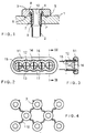
- Fig. 1 shows a finished pipe connection with the tube sheet 1 made of plastic, tube 2 made of metal and also made of plastic connecting element 3.
- the pipe 2 was frictionally expanded in a bore 1 'of the tube sheet 1 and the pipe end at the same time by a drawing punch, not shown 4 flared.
- the connecting piece 7 of the connecting element 3 is pressed into the tube 2, the funnel-shaped tube end 4 making it easier to press in.
- the connecting element 3 also has a flange 5 which is connected to the tube sheet 1 in a liquid- and gas-tight manner by means of a tongue and groove connection 6.
- An annular recess 8 is provided between the flange 5 and the connecting piece 7, in which the tube end 4 has space and which at the same time interrupts a capillary which is formed, which is particularly advantageous in the case of low internal pressures or underpressure. At high internal pressures, the seal between the connecting piece 7 and the inner tube wall is reinforced automatically.
- Connection piece 7 has a sharp edge 9 on its end face, which thereby abuts the pipe wall with a sharp finish. So there is no wedge effect and none Jam in the case of a rapidly flowing medium which flows through the through hole 10 of the connecting element 3.
- connecting element 11 for a flat tube 12.
- Connecting element 11 is reinforced by arch-shaped stiffeners 13, which are mutually supported by stiffening webs 14.
- guide elements 16 are arranged, which are designed so that they give the flowing medium a swirl in a freely selectable direction of rotation. (See arrows 17)
- Fig. 4 shows a further embodiment of the invention, wherein the connecting elements 3 are connected to a molded part by stretchable intermediate webs 18.
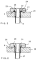
- Fig. 5 shows a further embodiment of the finished pipe connection, in which the pipe 19 is frictionally connected to the tube sheet 20 and the tube end 21 above the tube sheet 20 has a radially outwardly extending flange 22 with a substantially U-shaped cross section.
- a connecting element 23 is pressed into the tube 19 and is provided with an annular recess 24 directed towards the tube plate 20, which includes the flange 22.
- the tube sheet 20 has an annular nose 25 which engages in the flange 22.
- FIG. 6 shows a further embodiment of the invention, in which the tube end 26 of tube 27 above the tube sheet 28 has a flange 29 with an essentially S-shaped cross section.
Landscapes
- Engineering & Computer Science (AREA)
- Physics & Mathematics (AREA)
- Thermal Sciences (AREA)
- Mechanical Engineering (AREA)
- General Engineering & Computer Science (AREA)
- Heat-Exchange Devices With Radiators And Conduit Assemblies (AREA)
Claims (13)
- Échangeur thermique avec plusieurs tubes d'échange de chaleur (2) en métal, reliés sous pression à leurs extrémités par des fonds à tubes (1, 20, 28) en matière synthétique, caractérisé en ce que un élément de liaison (3, 11, 23, 30) séparé en matière synthétique avec au moins un alésage de passage (10, 15), un raccord (7) et une bride (5) sont prévus, le raccord (7) étant pressé dans le tube (2, 12, 19, 27) et la bride (5) étant reliée de façon étanche à l'eau et au gaz avec le fond à tubes (1) et que l'élément de liaison (3, 11, 23, 30) présente entre la bride (5) et le raccord (7) un évidement (8, 24, 31) annulaire dirigé vers le fond à tubes (1, 20, 28) et faisant saillie dans l'extrémité du tube (4, 21, 26).
- Échangeur thermique selon la revendication 1, caractérisé en ce que l'extrémité du tube (4, 21, 26) présente une déformation (22, 29) s'étendant radialement vers l'extérieur.
- Échangeur thermique selon la revendication 2, caractérisé en ce que la déformation est prévue comme collerette (22) présentant une section essentiellement en forme d'U.
- Échangeur thermique selon la revendication 3, caractérisé en ce que le fond à tubes (20) présente un tenon annulaire (25) engrènant dans la collerette (22).
- Échangeur thermique selon la revendication 2, caractérisé en ce que la déformation est prévue comme collerette (29) présentant une section essentiellement en forme de S.
- Échangeur thermique selon l'une des revendications 3 à 5, caractérisé en ce que la déformation (22, 29) définitive de l'extrémité du tube (21, 26) est atteinte pendant l'enfoncement de l'élément de liaison (23, 30), de sorte que l'évidement (24, 31) entoure avec un engagement positif la collerette (22, 29).
- Échangeur thermique selon l'une des revendications 1 à 6, caractérisé en ce que le raccord (7) présente sur sa face frontale une arête vive (9).
- Échangeur thermique selon la revendication 2, caractérisé en ce que le tube (2) est élargi à son extrémité (4) en forme d'entonnoir.
- Échangeur thermique selon l'une des revendications 1 à 8, caractérisé en ce que entre la bride (5) et le fond à tubes (1, 20, 28) est prévu un assemblage par rainure et languette (6).
- Échangeur thermique selon l'une des revendications 1 à 9, caractérisé en ce que un élément conducteur (16) est disposé dans l'alésage de passage (15), agissant sur le comportement d'écoulement de l'agent transporté.
- Échangeur thermique selon l'une des revendications 1 à 10, caractérisé en ce que l'élément de liaison (11) présente plusieurs alésages de passage (15) avec des éléments conducteurs (16) qui sont disposés de telle sorte que l'agent d'écoulement est déplacé avec un sens de rotation quelconque dans des alésages de passage (15) voisins.
- Échangeur thermique selon l'une des revendications 1 à 10, caractérisé en ce que les éléments de liaison (3) sont reliés par des entretoises (18).
- Échangeur thermique selon la revendication 12, caractérisé en ce que les entretoises (18) sont extensibles.
Applications Claiming Priority (4)
| Application Number | Priority Date | Filing Date | Title |
|---|---|---|---|
| DE4000823 | 1990-01-13 | ||
| DE19904000823 DE4000823A1 (de) | 1990-01-13 | 1990-01-13 | Waermetauscher mit rohrboden und anschlussstutzen |
| DE4005576 | 1990-02-22 | ||
| DE4005576A DE4005576A1 (de) | 1990-01-13 | 1990-02-22 | Waermetauscher mit rohrboden und anschlussstutzen |
Publications (3)
| Publication Number | Publication Date |
|---|---|
| EP0437825A2 EP0437825A2 (fr) | 1991-07-24 |
| EP0437825A3 EP0437825A3 (en) | 1992-01-08 |
| EP0437825B1 true EP0437825B1 (fr) | 1994-04-13 |
Family
ID=25889033
Family Applications (1)
| Application Number | Title | Priority Date | Filing Date |
|---|---|---|---|
| EP90125371A Expired - Lifetime EP0437825B1 (fr) | 1990-01-13 | 1990-12-22 | Echangeur de chaleur avec plaque d'extrémité et manchon de raccord |
Country Status (4)
| Country | Link |
|---|---|
| US (1) | US5107925A (fr) |
| EP (1) | EP0437825B1 (fr) |
| DE (2) | DE4005576A1 (fr) |
| ES (1) | ES2052151T3 (fr) |
Cited By (1)
| Publication number | Priority date | Publication date | Assignee | Title |
|---|---|---|---|---|
| DE102016116245A1 (de) * | 2016-08-31 | 2018-03-01 | Areva Gmbh | Strömungselement zur Erzeugung einer turbulenten Drallströmung und Wärmeübertragungsvorrichtung umfassend ein Strömungselement |
Families Citing this family (12)
| Publication number | Priority date | Publication date | Assignee | Title |
|---|---|---|---|---|
| FR2674321B1 (fr) * | 1991-03-20 | 1993-06-04 | Valeo Thermique Moteur Sa | Echangeur de chaleur a plusieurs rangees de tubes, en particulier pour vehicule automobile. |
| DE4309360C2 (de) * | 1993-03-23 | 1995-06-22 | Thermal Waerme Kaelte Klima | Heizungswärmetauscher für Kraftfahrzeuge |
| DE4338959C2 (de) * | 1993-11-15 | 1996-06-20 | Thermal Waerme Kaelte Klima | Wasser/Luft-Wärmetauscher für Kraftfahrzeuge und Herstellungsverfahren für diesen |
| DE9403848U1 (de) * | 1994-03-08 | 1994-05-11 | Behr Gmbh & Co, 70469 Stuttgart | Wärmetauscher für ein Kraftfahrzeug |
| CN1297133A (zh) * | 2000-11-30 | 2001-05-30 | 赵永镐 | 新型聚四氟乙烯管壳式换热器 |
| JP2006112759A (ja) * | 2004-10-18 | 2006-04-27 | Calsonic Kansei Corp | 熱交換器のヘッダタンクとコネクタの接合構造及び接合方法 |
| US20100052318A1 (en) * | 2008-08-27 | 2010-03-04 | Woodward Governor Company | System and Method of Joining Fluid Transporting Tube and Header Using Internal Ferrule |
| EP2881691A1 (fr) * | 2013-12-09 | 2015-06-10 | Balcke-Dürr GmbH | Échangeur de chaleur avec une plaque tubulaire et un manchon inséré |
| CN104266529A (zh) * | 2014-09-24 | 2015-01-07 | 无锡纳润特科技有限公司 | 列管式换热器的散热管与管板的连接结构 |
| CN110709646A (zh) * | 2017-03-17 | 2020-01-17 | 贝克特瓦斯公司 | 热交换器 |
| US11747094B2 (en) * | 2017-05-12 | 2023-09-05 | The Boeing Company | Hollow lattice thermal energy storage heat exchanger |
| CN111288834B (zh) * | 2020-04-13 | 2021-08-31 | 御隆膜科技南通有限公司 | 预制接头式氟塑料换热管与管板连接结构及安装方法 |
Family Cites Families (11)
| Publication number | Priority date | Publication date | Assignee | Title |
|---|---|---|---|---|
| DE333442C (de) * | 1919-10-15 | 1921-02-26 | Schweizerische Stellwerkfabrik | Waermeaustauschvorrichtung |
| US2099026A (en) * | 1936-05-15 | 1937-11-16 | Markel Orville | Condenser tube seal |
| FR878494A (fr) * | 1939-10-23 | 1943-01-21 | Radiateur pour machines à combustion d'aéronefs et de véhicules | |
| US2449616A (en) * | 1946-04-05 | 1948-09-21 | Pennella Samuel | Surface condenser |
| US2557360A (en) * | 1948-04-05 | 1951-06-19 | Pennella Samuel | Protective ferrule for heat exchanger tubes |
| NL7016348A (fr) * | 1970-11-09 | 1972-05-12 | ||
| FR2238545B1 (fr) * | 1973-07-25 | 1978-10-27 | Chausson Usines Sa | |
| DE3126030C2 (de) * | 1981-07-02 | 1983-04-14 | Süddeutsche Kühlerfabrik Julius Fr. Behr GmbH & Co KG, 7000 Stuttgart | Rohrverbindung für einen Wärmetauscher mit einer Vielzahl einzelner miteinander zu verbindender Teile |
| DE3328913A1 (de) * | 1983-08-10 | 1985-02-28 | Körting Hannover AG, 3000 Hannover | Einrichtung zur befestigung eines rohres in einer bohrung |
| DE8323074U1 (de) * | 1983-08-10 | 1988-10-27 | Henricy, Erich, 3005 Hemmingen | Einrichtung zur Befestigung eines Rohres in einer Bohrung |
| SU1388690A1 (ru) * | 1986-05-06 | 1988-04-15 | Всесоюзный научно-исследовательский и конструкторско-технологический институт компрессорного машиностроения | Способ закреплени трубы в трубной решетке теплообменника |
-
1990
- 1990-02-22 DE DE4005576A patent/DE4005576A1/de not_active Ceased
- 1990-12-22 ES ES90125371T patent/ES2052151T3/es not_active Expired - Lifetime
- 1990-12-22 EP EP90125371A patent/EP0437825B1/fr not_active Expired - Lifetime
- 1990-12-22 DE DE59005362T patent/DE59005362D1/de not_active Expired - Fee Related
-
1991
- 1991-01-08 US US07/638,846 patent/US5107925A/en not_active Expired - Fee Related
Cited By (1)
| Publication number | Priority date | Publication date | Assignee | Title |
|---|---|---|---|---|
| DE102016116245A1 (de) * | 2016-08-31 | 2018-03-01 | Areva Gmbh | Strömungselement zur Erzeugung einer turbulenten Drallströmung und Wärmeübertragungsvorrichtung umfassend ein Strömungselement |
Also Published As
| Publication number | Publication date |
|---|---|
| EP0437825A3 (en) | 1992-01-08 |
| DE59005362D1 (de) | 1994-05-19 |
| US5107925A (en) | 1992-04-28 |
| EP0437825A2 (fr) | 1991-07-24 |
| ES2052151T3 (es) | 1994-07-01 |
| DE4005576A1 (de) | 1991-09-26 |
Similar Documents
| Publication | Publication Date | Title |
|---|---|---|
| EP0437825B1 (fr) | Echangeur de chaleur avec plaque d'extrémité et manchon de raccord | |
| DE2519756C3 (de) | Wärmetauscher | |
| DE3026461A1 (de) | Verfahren zum formen eines endes eines metallischen rohres und derart geformtes rohr | |
| DE7419669U (de) | Waermeaustauscher mit einem buendel aus parallelen rohren und mit diesen zusammengebauten abstrahlplatten | |
| DE2525109A1 (de) | Spinnduesenplatte und verfahren zum einbauen eines spinnduesenoeffnungen enthaltenden einsatzes in die spinnduesenplatte | |
| DE102017109708A1 (de) | Kühlanordnung, Fluidsammler für eine Kühlanordnung sowie Verfahren zur Herstellung eines Fluidsammlers | |
| DE2113581C2 (de) | Flachrohr und Verfahren zum Herstellen desselben | |
| DE29614186U1 (de) | Wärmetauscher, insbesondere Wäschetrocknerkondensator, und zu dessen Herstellung bestimmte Rohranordnung | |
| EP2986878B1 (fr) | Manchon de serrage | |
| CH691290A5 (de) | Verfahren zur Bildung eines Vorformlings für die Innenhochdruckverformung. | |
| EP1882892B1 (fr) | Caloporteur spiralé et son procédé de fabrication | |
| DE3016135C2 (de) | Zieheinrichtung | |
| DE4334230C2 (de) | Verfahren zum Befestigen eines Profilteils in einem das Profilteil umgreifenden Hohlprofil | |
| DE69715919T2 (de) | Plattenwärmetauscher | |
| AT404188B (de) | Heizungs-plattenradiator | |
| EP0077058B1 (fr) | Robinet à boisseau sphérique | |
| DE4000823A1 (de) | Waermetauscher mit rohrboden und anschlussstutzen | |
| DE3102188A1 (de) | Stuetzring | |
| DE4435460A1 (de) | Vorrichtung zum Durchsetzfügen von sich überlappenden Blechteilen | |
| DE102006029821B3 (de) | Wärmetauscher | |
| DE2838497A1 (de) | Flansch | |
| DE2414966A1 (de) | Loetverbindung zweier ineinanderzufuegender teile | |
| DE4339962A1 (de) | Vorrichtung und Verfahren zur Herstellung von Sickenblechen mit planparallelen Außenkantenflächen | |
| DE3838245A1 (de) | Stuetzring fuer einen flachheizkoerper und verfahren zum herstellen eines stuetzrings | |
| DE3427369C2 (fr) |
Legal Events
| Date | Code | Title | Description |
|---|---|---|---|
| PUAI | Public reference made under article 153(3) epc to a published international application that has entered the european phase |
Free format text: ORIGINAL CODE: 0009012 |
|
| 17P | Request for examination filed |
Effective date: 19901222 |
|
| AK | Designated contracting states |
Kind code of ref document: A2 Designated state(s): DE ES FR GB IT SE |
|
| PUAL | Search report despatched |
Free format text: ORIGINAL CODE: 0009013 |
|
| AK | Designated contracting states |
Kind code of ref document: A3 Designated state(s): DE ES FR GB IT SE |
|
| 17Q | First examination report despatched |
Effective date: 19921127 |
|
| GRAA | (expected) grant |
Free format text: ORIGINAL CODE: 0009210 |
|
| AK | Designated contracting states |
Kind code of ref document: B1 Designated state(s): DE ES FR GB IT SE |
|
| REF | Corresponds to: |
Ref document number: 59005362 Country of ref document: DE Date of ref document: 19940519 |
|
| ITF | It: translation for a ep patent filed | ||
| REG | Reference to a national code |
Ref country code: ES Ref legal event code: FG2A Ref document number: 2052151 Country of ref document: ES Kind code of ref document: T3 |
|
| GBT | Gb: translation of ep patent filed (gb section 77(6)(a)/1977) |
Effective date: 19940708 |
|
| ET | Fr: translation filed | ||
| EAL | Se: european patent in force in sweden |
Ref document number: 90125371.6 |
|
| PLBE | No opposition filed within time limit |
Free format text: ORIGINAL CODE: 0009261 |
|
| STAA | Information on the status of an ep patent application or granted ep patent |
Free format text: STATUS: NO OPPOSITION FILED WITHIN TIME LIMIT |
|
| 26N | No opposition filed | ||
| PGFP | Annual fee paid to national office [announced via postgrant information from national office to epo] |
Ref country code: DE Payment date: 19980121 Year of fee payment: 8 |
|
| PGFP | Annual fee paid to national office [announced via postgrant information from national office to epo] |
Ref country code: SE Payment date: 19981127 Year of fee payment: 9 |
|
| PGFP | Annual fee paid to national office [announced via postgrant information from national office to epo] |
Ref country code: ES Payment date: 19981204 Year of fee payment: 9 |
|
| PGFP | Annual fee paid to national office [announced via postgrant information from national office to epo] |
Ref country code: GB Payment date: 19981215 Year of fee payment: 9 |
|
| PGFP | Annual fee paid to national office [announced via postgrant information from national office to epo] |
Ref country code: FR Payment date: 19981230 Year of fee payment: 9 |
|
| PG25 | Lapsed in a contracting state [announced via postgrant information from national office to epo] |
Ref country code: DE Free format text: LAPSE BECAUSE OF NON-PAYMENT OF DUE FEES Effective date: 19991001 |
|
| PG25 | Lapsed in a contracting state [announced via postgrant information from national office to epo] |
Ref country code: GB Free format text: LAPSE BECAUSE OF NON-PAYMENT OF DUE FEES Effective date: 19991222 |
|
| PG25 | Lapsed in a contracting state [announced via postgrant information from national office to epo] |
Ref country code: SE Free format text: LAPSE BECAUSE OF NON-PAYMENT OF DUE FEES Effective date: 19991223 |
|
| GBPC | Gb: european patent ceased through non-payment of renewal fee |
Effective date: 19991222 |
|
| EUG | Se: european patent has lapsed |
Ref document number: 90125371.6 |
|
| PG25 | Lapsed in a contracting state [announced via postgrant information from national office to epo] |
Ref country code: FR Free format text: LAPSE BECAUSE OF NON-PAYMENT OF DUE FEES Effective date: 20000831 |
|
| REG | Reference to a national code |
Ref country code: FR Ref legal event code: ST |
|
| PG25 | Lapsed in a contracting state [announced via postgrant information from national office to epo] |
Ref country code: ES Free format text: LAPSE BECAUSE OF NON-PAYMENT OF DUE FEES Effective date: 20001223 |
|
| REG | Reference to a national code |
Ref country code: ES Ref legal event code: FD2A Effective date: 20010113 |
|
| PG25 | Lapsed in a contracting state [announced via postgrant information from national office to epo] |
Ref country code: IT Free format text: LAPSE BECAUSE OF NON-PAYMENT OF DUE FEES;WARNING: LAPSES OF ITALIAN PATENTS WITH EFFECTIVE DATE BEFORE 2007 MAY HAVE OCCURRED AT ANY TIME BEFORE 2007. THE CORRECT EFFECTIVE DATE MAY BE DIFFERENT FROM THE ONE RECORDED. Effective date: 20051222 |