EP0439374A2 - Verfahren und Vorrichtung zur Wiederverwertung anorganischer Verbindungen - Google Patents
Verfahren und Vorrichtung zur Wiederverwertung anorganischer Verbindungen Download PDFInfo
- Publication number
- EP0439374A2 EP0439374A2 EP91300606A EP91300606A EP0439374A2 EP 0439374 A2 EP0439374 A2 EP 0439374A2 EP 91300606 A EP91300606 A EP 91300606A EP 91300606 A EP91300606 A EP 91300606A EP 0439374 A2 EP0439374 A2 EP 0439374A2
- Authority
- EP
- European Patent Office
- Prior art keywords
- gas
- inorganic
- liquid
- mixing
- hazardous waste
- Prior art date
- Legal status (The legal status is an assumption and is not a legal conclusion. Google has not performed a legal analysis and makes no representation as to the accuracy of the status listed.)
- Granted
Links
Images


Classifications
-
- C—CHEMISTRY; METALLURGY
- C03—GLASS; MINERAL OR SLAG WOOL
- C03B—MANUFACTURE, SHAPING, OR SUPPLEMENTARY PROCESSES
- C03B5/00—Melting in furnaces; Furnaces so far as specially adapted for glass manufacture
- C03B5/005—Melting in furnaces; Furnaces so far as specially adapted for glass manufacture of glass-forming waste materials
-
- B—PERFORMING OPERATIONS; TRANSPORTING
- B29—WORKING OF PLASTICS; WORKING OF SUBSTANCES IN A PLASTIC STATE IN GENERAL
- B29B—PREPARATION OR PRETREATMENT OF THE MATERIAL TO BE SHAPED; MAKING GRANULES OR PREFORMS; RECOVERY OF PLASTICS OR OTHER CONSTITUENTS OF WASTE MATERIAL CONTAINING PLASTICS
- B29B17/00—Recovery of plastics or other constituents of waste material containing plastics
- B29B2017/0094—Mobile recycling devices, e.g. devices installed in truck trailers
Definitions
- United States patent 3,659,979 to Schneider, et al. discloses a plant for manufacturing small structural elements out of concrete and includes a production station and a hardening station, both of which are transportable on flat-bed-type trailers to a specific site, unloaded, used, and then retransportable to another site.
- United States patent 4,072,453 to Oltmanns, et al. discloses a plant for the production of tubular articles such as corrugated drain pipes out of synthetic material which is mounted in a trailer for transport.
- the raw material is fed into the plant by a flexible conveying screw to fill the hopper of an extruder whereupon a forming and conveying device takes the extrudate to form the tubular product which is then wound upon a storage reel.
- United States patent 4,266,916 to Lubavs discloses a mobile block production plant wherein the producing station and curing station are separately mounted on mobile trailer beds with the curing station having at least two curing kilns, each capable of separate function.
- United States patent 1,454,082 to Schlosser discloses a facility for treatment of waste wherein the waste is separated as to type and treated and dealt with according to its nature and uses to be made thereof.
- Schlosser relates to a method of utilizing domestic and industrial garbage and other refuse.
- United States patent 3,893,656 to Opacic, et al. discloses a mobile unit for treating liquid waste having a bin for a powdered setting agent with an outlet at its bottom and a porous floor spaced above the bottom. Compressed air is delivered to the space beneath the floor to form a fluidized bed of setting agent above the floor. The setting agent is delivered to the mixing hopper in which it is mixed with liquid waste whereupon the mixture leaves the hopper.
- an embodiment of the inventive mobile inorganic recycling apparatus includes a sophisticated scrubber device through which a gas is taken to remove all hazardous materials therefrom and render the gas benign. While some of these patents teach some aspects of the inventive scrubber, none of these patents teaches all of the aspects thereof and any combination of these references does not teach all of the aspects of the present invention.
- a method of recycling inorganic hazardous waste material into useful products by chemically fixing inorganic constituent materials of said inorganic hazardous waste into a silicate matrix comprising the steps of:
- apparatus for recycling inorganic hazardous waste material into useful products by chemically fixing inorganic constituent materials of said inorganic hazardous waste into a silicate matrix comprising;
- the present invention overcomes or reduces the deficiencies found in the prior art as set forth hereinabove and provides in one embodiment a new and improved mobile inorganic recycling process and apparatus which combines convenience to the customer with adequate capacity in a portable system.
- the apparatus includes two mobile vehicles.
- the first vehicle comprises a mixing truck having a loading station for material to be processed, and a feed chute feeding material from the loading station to a feed hopper leading to an auger.
- the auger de-lumps the material whereupon it is fed via a feed conveyor to a reactor tank having fluid connection with a chemical storage area so that chemicals may be added to the reactor tank with material to be processed therein.
- the reactor tank has mounted therein a stirring device designed to thoroughly mix the material to be processed with the added chemicals.
- the functions of the auger, reactor tank, recirculation system and loading station may be combined into a single tank having a mixing blade with inner and outer helices, oppositely directed, with the outer helix in close proximity with the tank bottom.
- the tank has a bottom outlet port controlled by a valve and located above the tray loading station.
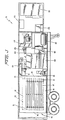
- Figure 1 shows a schematic top view of a first embodiment of the present invention including arrows depicting the direction of flow of the various aspects of the system.
- Figure 2 shows a side view of the mixing truck of the first embodiment of the present invention.
- Figure 3 shows a side view of the fixating trailer vehicle of the present invention.
- Figure 4 shows a cross-sectional schematic view of the inventive scrubber sub-combination.
- Figure 5 shows a schematic top view of a second embodiment of a mixing trailer.
- Figure 6 shows a side view of the mixing trailer of figure 5.
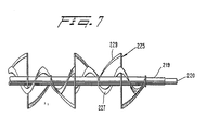
- Figure 7 shows a side view of the mixing blades of the mixer of the embodiment shown on figures 5 and 6.
- Organic substance treatment systems are generally geared to vaporization of a constituent or incineration whereas inorganic elements do not incinerate. They may become molten but do not break down any further and in most cases the vaporization temperatures of the inorganic substances are too high to be useful. Accordingly, systems designed to treat organic wastes may not be used to treat inorganic wastes.
- the present invention includes the use of a kiln or furnace to fire the waste material at high temperatures, any organic material which would be present would necessarily be destroyed during the kiln treating process.
- the present invention operates by chemically reacting the inorganic constituent substances in the mixture through a series of oxidation-reduction reactions which place the constituents into a chemical state which will allow subsequent binding. In order to cause these reactions to take place, a variety of inorganic acids and alkalies are used which will be described in greater detail hereinafter. After mixing such substances with the hazardous waste, the mixture is then further blended with silicates such as sand or clay which are included based upon the desired end product. After completely mixing all the constituent parts together, heat is imparted to the mixture to cause chemical reactions to take place causing the inorganic constituent materials to bind into a silicate matrix which is inert and inseparable by typical physical or chemical means. After chemically fixating the treated material, the resultant product is packaged and shipped to end users.
- a first embodiment of the inventive apparatus is designated by the reference numeral 1 and is seen to include a mixing truck 10 and a recycling trailer 40.
- the mixing truck includes a feed chute 11 situated at the rear of the truck 10 and designed to receive material from a customer material storage vessel 13 and to convey the material, consisting of hazardous inorganic waste, to a feed hopper 15 which leads the material to an auger 17 which acts to grind up any solid aspects thereof, with the auger having an outlet located above a conveyor belt 19 which conveys the material to the inlet manifold 21 of the reactor tank 23.
- the reactor tank includes a mixing device 25 including paddles 27 rotated by a motor 29.
- a pump 31 is provided which pumps the fluid from the tank 23 and through a conduit 33 to a valve 35 including two remotely controlled valves 37, 39.
- the passageway 33 has connected thereto a first branch passage 22 and a second branch passage 24 with the branch 22 recirculating the fluid back into the tank 23 and with the branch 24 comprising an outlet branch conveying the fluid to a container loading station 36 at the rear of the vehicle and having placed thereon a container 38 which has removably placed therein the outlet 26 of the conduit 24.
- containers 38 are filled with mixture from the conduit 24, they are conveyed by any desired means (not shown) to the recycling trailer.
- the valves 37 and 39 are solenoid actuated and may comprise a single valve head allowing only one of the branches to be open at any given time.
- the valve 39 when the valve 39 is opened to allow recirculation of fluid through the conduit 22 back to the reactor tank 23, the valve 37 will be closed precluding fluid flow out the outlet 26.
- the valve 39 is closed and the valve 37 is opened to allow fluid to be pumped by the pump 31 through the conduit 24 to the outlet 36 filling the container 38.
- treating chemicals from the chemical tank 28 are introduced into the reactor tank 23 via the conduit 32.
- solid chemicals may be loaded via chute 11, hopper 15, auger 17, conveyor belt 19 and inlet manifold 21.
- each container 38 is conveyed by any desired means from the container loading station 36 to a location adjacent ceramic-lined doors 41 located on a side wall 42 of the recycling trailer 40.
- the subject mixing truck may be simplified by combining the functions of the feed chute 11, feed hopper 15, auger 17, conveyer belt 19, inlet manifold 21 and reactor tank 23 into a single structure.
- the mixing trailer 200 is seen to be of the semi-trailer type.
- the mixing trailer 200 could be incorporated into a vehicle in the same manner as the mixing truck 10.
- the trailer 200 includes a mixer 201 including a loading door 203, a cover 205, an outlet port 207 connected to an outlet 209 via a gate valve 210 having an actuator stem 211 which is selectively reciprocated through the use of a hydraulic piston-cylinder 213.
- the hydraulic actuator 213 may be replaced with other actuation means such as, for example, a solenoid actuator, pneumatic actuator and the like.
- the outlet 209 is positioned directly above a tray loading station 215 wherein a tray 38 is seen to be supported on tray support 239 which is surrounded by the spill pan 217 which is provided to catch all overflow from the tray 39.
- the mixer 201 has extending therethrough an elongated drive shaft 219 which is rotated by a drive motor 221.
- a mixer blade 225 Fixedly mounted on the drive shaft 219 is a mixer blade 225 seen in figure 7 to include an inner ribbon helix 227 and an outer ribbon helix 229.
- the inner helix 227 is seen to rotate about the shaft 219 in a clockwise direction whereas the outer helix 229 is seen to rotate about the drive shaft 219 in a counter-clockwise direction.
- the mixer blade 225 is sized and configured to rotate in closely spaced relation to the bottom surface 202 of the mixer 201.
- the bottom surface 202 is made of a semi-cylindrical shape so that throughout the circumference of the surface 202, the outer helix 229 is in closely spaced relation with respect thereto.
- the interaction between the outer surfaces of the helix 229 and the inner surfaces of the surface 202 will facilitate de-lumping of materials within the mixer 201.
- an air compressor 230 mounted above the mixer drive 221 is an air compressor 230 which is provided to supply air to the various valves in the device as well as for general use in the manner that the air compressor 183, described hereinbelow, is provided.
- a dust collector 240 is provided within the trailer 200 and is provided to collect any dust which may be created by the mixing action of the mixer 201 or from any other source, since dust which may be created during the inventive process may be hazardous to workers and thus must be collected for safety reasons.
- a tank 250 is provided which may be utilized to store water, chemicals or other substances which may be selectively fed to the mixer 201.
- doors 241 and 243 are provided to provide access to a large storage area at the forward end of the trailer 200. Additional storage area is provided at the reference numeral 245 in front of the mixer 201 with vent fans 247, 249 also being provided adjacent thereto.
- an electrical panel 251, locker 253 and tool and part cabinet 255 may be provided.
- the mixer 201 In the operation of the mixer 201, it is seen that a loading chute and conveyor are eliminated by the top access 203 wherein hazardous materials to be treated may be dumped.
- the close proximity of the helix 229 of the mixer blade 225 to the surface 202 of the mixer 201 replaces the functions of the auger in allowing de-lumping of materials placed therein.
- the tank 250 is analogous to the tank 28 of the mixer truck 10 and the structure of the mixer blade 25 with the inner helix 227 and outer helix 229 replaces the functions of the recirculation conduits 33, 22 and renders the valves 37, 39 unnecessary.
- the conduit 24 and outlet 26 are replaced in function by the bottom outlet port 207, valve 210 and outlet 209.
- the loading station 36 is replaced by the loading station 215.
- the means which is utilized to transport the trays 38 from the container loading station 36 of the mixing truck 10 or the loading station 215 of the trailer 200 to a location adjacent the doors 41 on the recycling trailer 40 may be any desired means such as, for example, a conveyer belt system, a lift truck or other vehicle or an overhead crane system. Of course, any desired means may be employed in this regard.
- the fixation trailer is seen to include contained therein a kiln 43 having walls 45, 47 and 49 which are preferably made of a material lined with ceramic fiber so as to facilitate the withstanding of the high temperatures which are generated therein.
- Burners 51 extend through the walls 45 and 49 so that gas, preferably propane gas, may be ignited and burned within the chamber 53 within the kiln 43.
- propane gas preferably propane gas
- Propane is supplied to the burners 51 from a propane tank which may be contained separately from the trailer 40 with appropriate detachable fluid coupling therebetween.
- the ceramic fiberlined doors 41 combine with the walls 45, 47 and 49 and, with reference to figure 3, with the ceiling 42 and floor 44 to define a sealable chamber in which the trays 38 are removably placed on shelves (not shown but schematically depicted in figure 3 based upon the shown spacing of the trays 38).
- the purpose of the kiln or furnace 43 is to provide the energy needed for the final chemical reaction to occur.
- the examples discussed hereinafter were processed in a box kiln into which containers 38 filled with the reacted-blended material were placed.
- the box kiln used was designed employing gas fired burners, which may operate with propane or natural gas.
- the time sequences disclosed in the examples were used in this particular kiln.
- any kiln or furnace design can be used as long as minimum temperature requirements are met.
- An oven, [a unit capable of obtaining temperatures to 600°F-700°F]
- Furnaces such as an arc furnace have been used successfully in this recycling procedure. If such devices were employed, the process description would remain generally the same but the kiln time sequences would change.
- the reacted-blended material is placed into a crucible type vessel. Approximately 3 to 4 hours of kiln process time is required to make the material molten. At that point the vitrified material may be removed from the vessel or the reacted-blended material would flow at a rate into the furnace as finished material would flow out creating a continuous kiln sequence operation.
- the burners 51 are ignited to raise the temperature within the chamber 53 to a desired level, for example, 2,100 degrees Fahrenheit.
- gases form which may include hazardous substances incorporated therein in liquid, vapor or particulate form.
- the chamber 53 includes an outlet 55 connecting the chamber 53 with a scrubber 100 specifically designed to remove all hazardous particulate liquid and vapor by-products from the gas entering the scrubber 100 via the intake port 57.
- the scrubber 100 has an inlet port 101 and an outlet port 103 connected to a transition duct 105 in a downstream direction from outlet port 103 which has coupled thereto, on its outlet end, an exhaust fan 107 specifically designed to assist in pulling the gas through the scrubber 100 so that it may be treated.
- the inlet conduit 57 has connected thereto an inlet manifold 58 of the scrubber and, with particular reference to figure 4, it is seen that the inlet manifold 58 has mounted therein one or more nozzles 109 designed to spray liquid onto the gas as it enters the scrubber 100.
- the gas is forced to make a right-angle turn by impingement on the wall 113 and then is constrained to descend vertically through a passageway 111 which leads to a converging throat section 115 leading to a venturi throat 117 which is preferably rectangular in cross-sectional shape and which is fed through nozzles 119 with a further supply of low pressure water spray.
- the venturi structure causes the gas to have accelerated to from four to six times the velocity attained at the inlet manifold 58.
- the gas travels through a passage 121 of diverging cross-sectional area which allows gas deceleration.
- upstream of the throat 117 the gas is dry whereas downstream of the throat 117, the gas is wet by virtue of the liquor sprayed thereon through nozzles 119, and this structure and function sets up complete separation of the wet-dry zones through the venturi structure.
- a quench spray would then be supplied at the scrubber inlet 137, via spray nozzles 107. A portion of the quench water would then be carried to the venturi section.
- the reaction of the gas with the liquid in the venturi throat 117 is designed to cause the gas to reach near 100 percent saturation while causing any agglomerated particles and other fine materials to be trapped within droplets of scrubbing liquor with the shearing effect of the liquor/gas interaction using a significant portion of the energy which is expended within the throat of the venturi 117 to thereby facilitate the breaking up of the liquor into fine liquid particles offering a large surface area for chemical reactions to start and/or be completed.
- the reservoir 123 includes a target box 128 fluidly connected with the remainder of the reservoir 123 via ports 122.
- the target box 128 is centrally located in the reservoir 123 and is the location where most of the gas flow impinges. This liquid is designated in the figure by the reference numeral 125.
- a closed circulating system is included in the scrubber 100 which includes the reservoir 123, conduit 127, pump 129, conduit 131, passageway 133 with its nozzle outlets 119, passageway 135 with its nozzle outlets 137, and passageway 139 with its nozzle outlets 109.
- the structure of the scrubber 100 allows liquid which has been used in the system to drain downwardly into the reservoir 123 wherein the drain outlet 124 allows the liquid to drain into the conduit 127 and to be recirculated through the system.
- the gas After impingement of the gas upon the liquid surface in the reservoir 123, the gas makes a 180° turn and begins to ascend up through the scrubber 100.
- the scrubber system has been designed primarily for cooling, saturation and particulate transfer, both solid and liquid, from the gas phase to the liquid phase. Since this liquid break-up and mixing is quite thorough due to the unique design of inventive scrubber, chemicals may be added into the recycled scrubbing liquor and the resulting reaction will allow for the chemical transfer of contaminants from the gas phase into the liquid phase.
- the scrubber design allows additives to be injected directly into the liquid recycling system.
- FIGS. 1 and 3 illustrate in the recycling trailer 40 a chemical feed system 62 designed to supply chemicals as desired to the reservoir 123.
- a chemical feed system 62 designed to supply chemicals as desired to the reservoir 123.
- the reservoir 123 may have incorporated therewith a pH sensing system designed to sense the pH of the liquid 125 within the reservoir 123 and responsive to the changes of pH of the liquid 125, causing chemicals from the chemical feed system 62 to be added to the liquid 125 to maintain a predetermined pH level whereupon the chemical feed system 62 is deactivated until the predetermined pH level chosen has changed.
- the gas After impingement of the gas upon the liquid surface in the reservoir 123, the gas makes a 180 degree turn and begins to ascend up through the scrubber 100.
- the gas passes through a scrubber section including an orifice plate 141 seen to have a plurality of V-shaped orifices converging in the direction of flow.
- the orifice plate 141 is specifically designed to disperse the gas uniformly over the entire cross section of the scrubber body and is sized, in the preferred embodiment, for approximately forty percent open area with the further purpose of providing support for the packing 143 downstream thereof.
- the packing 143 is contained within a liquid/gas dephaser section into which the gas enters after being slowed down by fifty to sixty percent from its speed entering the orifice plate 141 by the reduction in travel area to the forty percent figure described hereinabove.
- the orifice plate is useful in separating apart virtually all droplets of fluid with particulate matter imbedded therein which are contained in the gas flow. As the gas enters the packing 143, liquor is spraying from the nozzles 137 and runs downwardly into the packing 143 to impinge upon the gas.
- the combination of this liquid flowing downwardly through the packing and the liquid entrained in the gas from the target box 128 of the reservoir 123 combines to form a layer of scrubbing liquid of approximately two inches to three inches deep above the orifice plate 141. With such a thickness of liquid existing within the packing 143, the gas will bubble through this area and thereafter enter uniformly into the packing 143 above the liquid level.
- the packing 143 comprises an extended surface scrubber packing having approximately fifty to eighty square feet of surface area for each cubic foot of packing.
- the nozzles 137 evenly disperse liquid at a sufficient rate to maintain liquid flow through the packing at approximately eighty percent of the total flood volume.
- the gases are subjected to a slow, tortuous path flow through the packing and counter-current flow of liquid which flows downwardly through the force of gravity through the orifices in the orifice plate 141 and thereafter into the reservoir 123 wherein the liquid is recirculated as described hereinabove.
- the packing 143 defines a region in the scrubber 100 which may be termed the "chemical reaction center" of the scrubber where sufficient time is allowed for efficient gas transfer into the scrubbing liquid. As seen in figure 4, above the packing 143 and above the nozzles 137, an open air region 145 is provided to facilitate final separation of liquid droplets.
- the packing 143 with the liquid supply thereto also serves as a condenser which acts to reclaim liquid which would normally be lost in a steam plume.
- the open area 145 has been described hereinabove as being a region where final separation of liquid droplets may take place.
- a demister 147 which is constructed, in the preferred embodiment, of a fine fiber mesh supported by a rigid frame including the passageway 111. The demister 147 removes all remaining liquid from the gas stream. As the demister is located, a small volume of liquid from the packing 143 is allowed to reach the bottom side of the pad which has the function of a final high-efficiency wet filter to provide gas resistance for uniform gas flow.
- the gas passes through an orifice plate 149 which is provided to ensure even flow out of the demister pad 147 and toward the scrubber outlet.
- the outlet 103 Downstream of the orifice plate 149, the outlet 103 is provided of a sufficient size to handle the system design flow parameters in cubic feet per minute.
- the outlet 103 comprises the only outlet from the scrubber 100 and all gas must pass therethrough and thence via the exhaust fan 107 to a discharge.
- a cleanout box 155 is provided to give access to the reservoir 123 so as to allow the cleaning of the reservoir 123 as desired.
- the drain 157 allows periodic draining of the reservoir or flow of liquid contained therein to a separate filtering system (not shown) where the liquid may be cleaned.
- the filter 159 may be provided in the passage 127 with the filter 159 being located where it may easily be periodically cleaned.
- a level sensor may be contained in the reservoir adjacent the cleanout box 155 and connected to a source of additional scrubbing liquid with a pump interposed therebetween.
- the pump (not shown) will be activated to pump additional scrubbing liquid from a reservoir (not shown) into the reservoir 123 until the level of fluid 125 and 126 within the reservoir 123 rises to a predetermined level as sensed by the above described level sensor.
- the above described pump will be deactivated until such time as the level of liquid within the reservoir 123 again is reduced to a predetermined low level.
- the above described pump may be connected to the cleanout box 155 and the cleanout box 155 may be provided with a viewport 161 allowing viewing of the reservoir 123 without opening the cleanout box 155.
- the gas is drawn into the inlet 109 and is immediately quenched at the nozzle 139.
- the gases move through an impingement duct 111, 113 and directly into a high-energy venturi throat 115, 117, 121.
- further liquid is sprayed onto the gas through the nozzles 119 and the gas is discharged from the venturi section onto the surface of water within the target box 128 of the reservoir 123 where more mixing and scrubbing takes place.
- the mixture is forced through the orifice plate 141 after turning through 180 degrees for liquid-gas separation.
- the gases are drawn through the absorption section including the packing 143, the water flowing downwardly from the nozzles 137 combined with the packing structure causes a slow tortuous path to be created which must be traversed by the gas to provide a final cleaning of the gas.
- the gas passes through a final demister 147, through a further orifice plate 149 designed to render the flow uniform and thereafter out the outlet 103 and thence via the exhaust fan 107 to discharge.
- the scrubbing liquid is recirculated by a pump which supplies water to the inlet quencher 109, venturi throat nozzles 119 and absorption section nozzles 137.
- the water level within the reservoir 123 is maintained by an overflow sensing level control system.
- the scrubber may be set up to concentrate its effectiveness on gas scrubbing, particulate collection or any combination thereof.
- Materials of the various component parts of the scrubber 100 are designed to handle gas temperatures of at least 2500 degrees Fahrenheit as well as the corrosive nature of the gases.
- the scrubber 100 is small in size for the operations which it performs due to the central passage surrounded by an annulus to provide an elongated flow path within a small area.
- the recycling truck 40 may be provided with venting means 170, 172, 174, 176, 178 and 180 (figure 2) so that heat which is created within the trailer 40 may be dissipated. A separate vent is utilized to vent the gases which are exhausted by the fan 107.
- the trailer 40 may include an office 171 having a desk 173 where forms, charts and records may be stored with the office 171 including a heater/air conditioner 175 as well as control and indicator panels 177, 179.
- a water tank 181 is provided within the trailer 40 and the water contained therein is supplied to the reservoir 123 of the scrubber 100 in the manner described hereinabove.
- an air compressor 183 may be provided for the convenience of the operator of the trailer 40 so that air may be blown where desired for clean-up purposes and the like.
- a combustion air fan 185 may also be provided and may be connected by suitable conduits to the interior of the kiln 43 to improve combustion therein of gases flowing out the nozzles 51.
- a filter cake derived from sodium hydroxide precipitation of copper, tin and lead plating baths through a plate and frame filter press includes the following composition:
- a filter cake derived from calcium hydroxide precipitation of iron and nickel etching operation to a drum filter includes the following composition:
- a filter cake derived from chrome - nickel anodizing operation, precipitation with ferrous sulfate to a plate and frame filter press includes the following composition:
- a filter cake derived from various plating lines, i.e., nickel-chrome, copper zinc - precipitated with magnesium hydroxide to a plate and frame filter press includes the following composition:
- the inorganic constituent materials have bound into a silicate matrix which is inert and inseparable by typical physical or chemical means.
- a silicate matrix which is inert and inseparable by typical physical or chemical means.
- the silicate matrix forming the finished product of the present invention may be broken, cracked, even pulverized without release of hazardous wastes, which are inseparably bonded into the silicate matrix.
- the finished product may safely be used to make grinding wheels, stones, sandpaper, shot blast material and other abrasives, refractory materials such as brick and other masonry materials, road bed materials such-as the base thereof, ceramic glazes, pigments, frit, colorants, building materials such as roofing materials, flooring, wall tiles, faschia, etc. Numerous other applications exist.
Landscapes
- Chemical & Material Sciences (AREA)
- Engineering & Computer Science (AREA)
- Materials Engineering (AREA)
- Organic Chemistry (AREA)
- Processing Of Solid Wastes (AREA)
- Organic Low-Molecular-Weight Compounds And Preparation Thereof (AREA)
- Saccharide Compounds (AREA)
- Treating Waste Gases (AREA)
Applications Claiming Priority (3)
| Application Number | Priority Date | Filing Date | Title |
|---|---|---|---|
| US471042 | 1990-01-26 | ||
| US07/471,042 US5009511A (en) | 1987-10-20 | 1990-01-26 | Inorganic recycling process |
| CA002034930A CA2034930C (en) | 1990-01-26 | 1991-01-25 | Mobile inorganic recycling process and apparatus |
Publications (3)
| Publication Number | Publication Date |
|---|---|
| EP0439374A2 true EP0439374A2 (de) | 1991-07-31 |
| EP0439374A3 EP0439374A3 (en) | 1991-12-18 |
| EP0439374B1 EP0439374B1 (de) | 1996-12-18 |
Family
ID=25674460
Family Applications (1)
| Application Number | Title | Priority Date | Filing Date |
|---|---|---|---|
| EP91300606A Expired - Lifetime EP0439374B1 (de) | 1990-01-26 | 1991-01-25 | Verfahren und Vorrichtung zur Wiederverwertung anorganischer Verbindungen |
Country Status (5)
| Country | Link |
|---|---|
| US (1) | US5009511A (de) |
| EP (1) | EP0439374B1 (de) |
| AT (1) | ATE146369T1 (de) |
| CA (1) | CA2034930C (de) |
| DE (1) | DE69123609T2 (de) |
Cited By (2)
| Publication number | Priority date | Publication date | Assignee | Title |
|---|---|---|---|---|
| EP0545851A1 (de) * | 1991-12-04 | 1993-06-09 | SOLVAY UMWELTCHEMIE GmbH | Dekontamination asbestkontaminierter Materialien |
| WO1999043756A1 (en) * | 1998-02-24 | 1999-09-02 | Kemira Chemicals Oy | Method for improving the stability of a slurry |
Families Citing this family (33)
| Publication number | Priority date | Publication date | Assignee | Title |
|---|---|---|---|---|
| US5220111A (en) * | 1991-09-10 | 1993-06-15 | Air Products And Chemicals, Inc. | Fixation of heavy metals in scrubbed municipal solid waste incinerator ash |
| US5164174A (en) * | 1991-10-11 | 1992-11-17 | Reynolds Metals Company | Detoxification of aluminum spent potliner by thermal treatment, lime slurry quench and post-kiln treatment |
| US5273566A (en) * | 1993-01-26 | 1993-12-28 | International Environmelting Corporation | Process for producing an environmentally acceptable abrasive product from hazardous wastes |
| US5424260A (en) * | 1994-02-07 | 1995-06-13 | Aluminum Waste Technology, Inc. | Method of recycling aluminum dross |
| US6200473B1 (en) * | 1998-11-06 | 2001-03-13 | G. Scott Fahey | In-transit water treatment system |
| US6155747A (en) * | 1999-01-07 | 2000-12-05 | The United States Of America As Represented By The Secretary Of The Navy | Mobile modular warehouse structure for containment and handling of hazardous materials |
| AR023049A1 (es) * | 1999-09-21 | 2002-09-04 | Kadae S A | Equipo movil autonomo para el reciclado de residuos plasticos. |
| US6901885B1 (en) * | 2004-01-29 | 2005-06-07 | Crystal Spring Colony Farms Ltd. | Apparatus for applying a tattoo to a hog prior to market |
| US7716146B2 (en) * | 2006-12-22 | 2010-05-11 | Verizon Patent And Licensing Inc. | Network management system utilizing a neural network |
| US8382075B2 (en) * | 2007-01-19 | 2013-02-26 | Heartland Technology Partners, Llc | Air stripper |
| US8425665B2 (en) * | 2007-01-19 | 2013-04-23 | Heartland Technology Partners, Llc | Fluid scrubber |
| US7832714B2 (en) | 2007-01-19 | 2010-11-16 | Heartland Technology Partners Llc | Desalination system |
| US8136797B2 (en) * | 2007-01-19 | 2012-03-20 | Heartland Technology Partners, Llc | Cooling tower |
| US10005678B2 (en) | 2007-03-13 | 2018-06-26 | Heartland Technology Partners Llc | Method of cleaning a compact wastewater concentrator |
| US8801897B2 (en) * | 2007-03-13 | 2014-08-12 | Heartland Technology Partners Llc | Compact wastewater concentrator and contaminant scrubber |
| US8790496B2 (en) * | 2007-03-13 | 2014-07-29 | Heartland Technology Partners Llc | Compact wastewater concentrator and pollutant scrubber |
| US8741100B2 (en) | 2007-03-13 | 2014-06-03 | Heartland Technology Partners Llc | Liquid concentrator |
| US8679291B2 (en) * | 2007-03-13 | 2014-03-25 | Heartland Technology Partners Llc | Compact wastewater concentrator using waste heat |
| MX2010010053A (es) * | 2008-03-13 | 2010-10-04 | 3M Innovative Properties Co | Granulos. |
| US8124231B2 (en) * | 2009-02-09 | 2012-02-28 | 3M Innovative Properties Company | Dust suppressants |
| CN102356046A (zh) | 2009-02-12 | 2012-02-15 | 中心地带科技股份有限公司 | 利用废热的紧凑型废水浓缩器 |
| EP2245941A1 (de) * | 2009-04-27 | 2010-11-03 | 3x Technology | Vorrichtung zum Abtauen oder Kühlen eines Lebensmittelprodukts |
| US8721771B2 (en) | 2011-01-21 | 2014-05-13 | Heartland Technology Partners Llc | Condensation plume mitigation system for exhaust stacks |
| US20120210997A1 (en) * | 2011-02-17 | 2012-08-23 | Mcnulty Peter Drummond | Method and device for generating steam and low oxygen gas |
| US9296624B2 (en) | 2011-10-11 | 2016-03-29 | Heartland Technology Partners Llc | Portable compact wastewater concentrator |
| US8808497B2 (en) | 2012-03-23 | 2014-08-19 | Heartland Technology Partners Llc | Fluid evaporator for an open fluid reservoir |
| US8741101B2 (en) | 2012-07-13 | 2014-06-03 | Heartland Technology Partners Llc | Liquid concentrator |
| DE102013100463B3 (de) * | 2013-01-17 | 2014-06-12 | Ald Vacuum Technologies Gmbh | Schmelzeinrichtung zum Konsolidieren von kontaminiertem Schrott |
| US8585869B1 (en) | 2013-02-07 | 2013-11-19 | Heartland Technology Partners Llc | Multi-stage wastewater treatment system |
| US9199861B2 (en) | 2013-02-07 | 2015-12-01 | Heartland Technology Partners Llc | Wastewater processing systems for power plants and other industrial sources |
| US10676674B1 (en) | 2014-02-03 | 2020-06-09 | Modern Recovery Systems, Inc. | Method, apparatus and system for processing materials for recovery of constituent components and use of such components in asphalt |
| US9932524B1 (en) | 2014-02-03 | 2018-04-03 | Modern Recovery Systems, Inc. | Method, apparatus and system for processing materials for recovery of constituent components |
| WO2020243510A1 (en) | 2019-05-31 | 2020-12-03 | Heartland Technology Partners Llc | Harmful substance removal system and method |
Family Cites Families (22)
| Publication number | Priority date | Publication date | Assignee | Title |
|---|---|---|---|---|
| US3334471A (en) * | 1966-08-11 | 1967-08-08 | Robert A Herron | Moisture control unit |
| DD112583A3 (de) * | 1970-02-20 | 1975-04-20 | ||
| US3862746A (en) * | 1971-05-10 | 1975-01-28 | Arvel O Franz | Slurry unloading of bulk alkaline earth metal carbonates |
| US3942970A (en) * | 1971-11-08 | 1976-03-09 | Orgonics, Inc. | Process for treating sewage sludge and fertilizer products thereof |
| US3870082A (en) * | 1972-12-26 | 1975-03-11 | Micron Eng Inc | Venturi-type devices |
| NL7300109A (en) * | 1973-01-04 | 1974-07-08 | Thermal destruction of aq. effluents - by mixing them with clay and firing to make ceramics | |
| JPS5630079B2 (de) * | 1973-07-09 | 1981-07-13 | ||
| CA1003777A (en) * | 1974-01-10 | 1977-01-18 | David Krofchak | Solidification of tailings from oil sands |
| GB1454073A (en) * | 1974-02-21 | 1976-10-27 | Bischoff Gasreinigung | Plant for cleaning the waste gases from a refuse burning plant |
| JPS5152678A (en) * | 1974-10-15 | 1976-05-10 | Ebara Infilco | Haikibutsuno shorihoho |
| JPS5187474A (ja) * | 1975-01-31 | 1976-07-31 | Shinnippon Kokan Kk | Juriarukarigakyozonsurujukinzokusuisankabutsusuratsujinoshoriho |
| JPS5232635A (en) * | 1975-09-08 | 1977-03-12 | Citizen Watch Co Ltd | Synchronous signal generating method of serial printer |
| US4046689A (en) * | 1976-07-09 | 1977-09-06 | Argyll Marion H | Method and apparatus for transporting sludge while rendering it for conversion into fertilizer |
| FR2359626A2 (fr) * | 1976-07-28 | 1978-02-24 | Sacilor | Procede et dispositif d'epuration de gaz ou de fumees poussiereuses |
| US4177575A (en) * | 1977-09-19 | 1979-12-11 | Cannon Limited | Organic material treatment process |
| IT1091453B (it) * | 1977-11-10 | 1985-07-06 | Whitehad Motofides Spa | Filtro aria a bagno d'olio |
| DE2917123A1 (de) * | 1978-04-28 | 1979-11-08 | Nihon Automatic Machinery Mfg | Verfahren und vorrichtung zum behandeln von verunreinigtem wasser |
| US4263024A (en) * | 1979-10-10 | 1981-04-21 | Venturmation, Inc. | Air cleaning device |
| US4266916A (en) * | 1980-02-14 | 1981-05-12 | Lubavs Arnold A | Mobile block production plant |
| US4394139A (en) * | 1982-03-04 | 1983-07-19 | Ecolaire Incorporated | Direct contact condenser and separating method |
| US4600514A (en) * | 1983-09-15 | 1986-07-15 | Chem-Technics, Inc. | Controlled gel time for solidification of multi-phased wastes |
| US4657681A (en) * | 1985-04-22 | 1987-04-14 | Hughes William L | Method of converting organic material into useful products and disposable waste |
-
1990
- 1990-01-26 US US07/471,042 patent/US5009511A/en not_active Expired - Lifetime
-
1991
- 1991-01-25 DE DE69123609T patent/DE69123609T2/de not_active Expired - Fee Related
- 1991-01-25 AT AT91300606T patent/ATE146369T1/de not_active IP Right Cessation
- 1991-01-25 EP EP91300606A patent/EP0439374B1/de not_active Expired - Lifetime
- 1991-01-25 CA CA002034930A patent/CA2034930C/en not_active Expired - Fee Related
Cited By (2)
| Publication number | Priority date | Publication date | Assignee | Title |
|---|---|---|---|---|
| EP0545851A1 (de) * | 1991-12-04 | 1993-06-09 | SOLVAY UMWELTCHEMIE GmbH | Dekontamination asbestkontaminierter Materialien |
| WO1999043756A1 (en) * | 1998-02-24 | 1999-09-02 | Kemira Chemicals Oy | Method for improving the stability of a slurry |
Also Published As
| Publication number | Publication date |
|---|---|
| US5009511A (en) | 1991-04-23 |
| DE69123609D1 (de) | 1997-01-30 |
| CA2034930C (en) | 2001-08-28 |
| EP0439374A3 (en) | 1991-12-18 |
| ATE146369T1 (de) | 1997-01-15 |
| DE69123609T2 (de) | 1997-07-10 |
| CA2034930A1 (en) | 1992-07-26 |
| EP0439374B1 (de) | 1996-12-18 |
Similar Documents
| Publication | Publication Date | Title |
|---|---|---|
| US5009511A (en) | Inorganic recycling process | |
| US4165289A (en) | System for the clarification of waste water and utilization of waste products | |
| US5711018A (en) | Rotary kiln treatment of potliner | |
| CN108800152B (zh) | 具有分类密闭进料系统的危险废弃物洁净处理系统 | |
| DE2321194A1 (de) | Verfahren und vorrichtung zur beseitigung von fluessigkeiten in einem fliessbettreaktor | |
| US3859174A (en) | Recovery of potable water from sanitary waste using solid wastes and refuse as a heat source | |
| CN109990301B (zh) | 一种油类污染物负压反烧设备及回收油的方法 | |
| US4050900A (en) | Incineration apparatus | |
| KR20060100022A (ko) | 가연성 폐기물 무공해 탄화처리로 에너지생산 방법과 그시스템과 그리고 크랙킹 촉매와 그 제조방법 | |
| CN1342319B (zh) | 从基质中分离成分的设备 | |
| CN107470318B (zh) | 铝灰梯级利用装置 | |
| JP4460387B2 (ja) | 廃棄物及び汚染物質の減容・無害化処理方法及び装置 | |
| CN205991497U (zh) | 危险废弃物洁净处理系统 | |
| US4204979A (en) | Method of processing activated carbon | |
| CN111550796A (zh) | 一种用于焙烧工业废杂盐的焙烧设备及焙烧方法 | |
| US4202282A (en) | Method of incineration | |
| US20040073078A1 (en) | Method for decomposing organic substance | |
| CN213446868U (zh) | 一种处理脱硫渣的水泥窑的炉渣回收装置 | |
| CN206337135U (zh) | 一种油泥资源化处理系统 | |
| CN100467098C (zh) | 燃煤锅炉烟气脱硫方法及装置 | |
| CN114623446B (zh) | 危险废物熔融固化处理系统 | |
| CN213930936U (zh) | 危险废物熔融固化处理系统 | |
| GB2607406A (en) | Process for ash remediation | |
| DE19731027C1 (de) | Verfahren und Einrichtung zur umweltschonenden Entsorgung von vorzugsweise lose oder in kleinen Gebinden vorliegendem Gefahrengut | |
| JPH0796296A (ja) | 無機物の再循環方法および装置 |
Legal Events
| Date | Code | Title | Description |
|---|---|---|---|
| PUAI | Public reference made under article 153(3) epc to a published international application that has entered the european phase |
Free format text: ORIGINAL CODE: 0009012 |
|
| AK | Designated contracting states |
Kind code of ref document: A2 Designated state(s): AT BE CH DE DK ES FR GB GR IT LI LU NL SE |
|
| PUAL | Search report despatched |
Free format text: ORIGINAL CODE: 0009013 |
|
| AK | Designated contracting states |
Kind code of ref document: A3 Designated state(s): AT BE CH DE DK ES FR GB GR IT LI LU NL SE |
|
| 17P | Request for examination filed |
Effective date: 19920609 |
|
| 17Q | First examination report despatched |
Effective date: 19940513 |
|
| GRAG | Despatch of communication of intention to grant |
Free format text: ORIGINAL CODE: EPIDOS AGRA |
|
| GRAH | Despatch of communication of intention to grant a patent |
Free format text: ORIGINAL CODE: EPIDOS IGRA |
|
| GRAH | Despatch of communication of intention to grant a patent |
Free format text: ORIGINAL CODE: EPIDOS IGRA |
|
| GRAA | (expected) grant |
Free format text: ORIGINAL CODE: 0009210 |
|
| AK | Designated contracting states |
Kind code of ref document: B1 Designated state(s): AT BE CH DE DK ES FR GB GR IT LI LU NL SE |
|
| PG25 | Lapsed in a contracting state [announced via postgrant information from national office to epo] |
Ref country code: IT Free format text: LAPSE BECAUSE OF FAILURE TO SUBMIT A TRANSLATION OF THE DESCRIPTION OR TO PAY THE FEE WITHIN THE PRESCRIBED TIME-LIMIT;WARNING: LAPSES OF ITALIAN PATENTS WITH EFFECTIVE DATE BEFORE 2007 MAY HAVE OCCURRED AT ANY TIME BEFORE 2007. THE CORRECT EFFECTIVE DATE MAY BE DIFFERENT FROM THE ONE RECORDED. Effective date: 19961218 Ref country code: GR Free format text: LAPSE BECAUSE OF FAILURE TO SUBMIT A TRANSLATION OF THE DESCRIPTION OR TO PAY THE FEE WITHIN THE PRESCRIBED TIME-LIMIT Effective date: 19961218 Ref country code: NL Free format text: LAPSE BECAUSE OF FAILURE TO SUBMIT A TRANSLATION OF THE DESCRIPTION OR TO PAY THE FEE WITHIN THE PRESCRIBED TIME-LIMIT Effective date: 19961218 Ref country code: ES Free format text: THE PATENT HAS BEEN ANNULLED BY A DECISION OF A NATIONAL AUTHORITY Effective date: 19961218 Ref country code: AT Effective date: 19961218 Ref country code: BE Effective date: 19961218 Ref country code: DK Effective date: 19961218 |
|
| REF | Corresponds to: |
Ref document number: 146369 Country of ref document: AT Date of ref document: 19970115 Kind code of ref document: T |
|
| REF | Corresponds to: |
Ref document number: 69123609 Country of ref document: DE Date of ref document: 19970130 |
|
| PG25 | Lapsed in a contracting state [announced via postgrant information from national office to epo] |
Ref country code: LU Free format text: LAPSE BECAUSE OF NON-PAYMENT OF DUE FEES Effective date: 19970131 |
|
| PG25 | Lapsed in a contracting state [announced via postgrant information from national office to epo] |
Ref country code: SE Effective date: 19970318 Ref country code: GB Effective date: 19970318 |
|
| ET | Fr: translation filed | ||
| REG | Reference to a national code |
Ref country code: CH Ref legal event code: NV Representative=s name: A. BRAUN, BRAUN, HERITIER, ESCHMANN AG PATENTANWAE |
|
| NLV1 | Nl: lapsed or annulled due to failure to fulfill the requirements of art. 29p and 29m of the patents act | ||
| PLBE | No opposition filed within time limit |
Free format text: ORIGINAL CODE: 0009261 |
|
| STAA | Information on the status of an ep patent application or granted ep patent |
Free format text: STATUS: NO OPPOSITION FILED WITHIN TIME LIMIT |
|
| GBPC | Gb: european patent ceased through non-payment of renewal fee |
Effective date: 19970318 |
|
| 26N | No opposition filed | ||
| PGFP | Annual fee paid to national office [announced via postgrant information from national office to epo] |
Ref country code: DE Payment date: 20001206 Year of fee payment: 11 |
|
| PGFP | Annual fee paid to national office [announced via postgrant information from national office to epo] |
Ref country code: FR Payment date: 20001229 Year of fee payment: 11 |
|
| PGFP | Annual fee paid to national office [announced via postgrant information from national office to epo] |
Ref country code: CH Payment date: 20010119 Year of fee payment: 11 |
|
| PG25 | Lapsed in a contracting state [announced via postgrant information from national office to epo] |
Ref country code: CH Free format text: LAPSE BECAUSE OF NON-PAYMENT OF DUE FEES Effective date: 20020131 Ref country code: LI Free format text: LAPSE BECAUSE OF NON-PAYMENT OF DUE FEES Effective date: 20020131 |
|
| PG25 | Lapsed in a contracting state [announced via postgrant information from national office to epo] |
Ref country code: DE Free format text: LAPSE BECAUSE OF NON-PAYMENT OF DUE FEES Effective date: 20020801 |
|
| REG | Reference to a national code |
Ref country code: CH Ref legal event code: PL |
|
| PG25 | Lapsed in a contracting state [announced via postgrant information from national office to epo] |
Ref country code: FR Free format text: LAPSE BECAUSE OF NON-PAYMENT OF DUE FEES Effective date: 20020930 |
|
| REG | Reference to a national code |
Ref country code: FR Ref legal event code: ST |