EP0440245B1 - Circuit d'alimentation - Google Patents
Circuit d'alimentation Download PDFInfo
- Publication number
- EP0440245B1 EP0440245B1 EP91101315A EP91101315A EP0440245B1 EP 0440245 B1 EP0440245 B1 EP 0440245B1 EP 91101315 A EP91101315 A EP 91101315A EP 91101315 A EP91101315 A EP 91101315A EP 0440245 B1 EP0440245 B1 EP 0440245B1
- Authority
- EP
- European Patent Office
- Prior art keywords
- reverse
- full
- circuit
- switching means
- power source
- Prior art date
- Legal status (The legal status is an assumption and is not a legal conclusion. Google has not performed a legal analysis and makes no representation as to the accuracy of the status listed.)
- Expired - Lifetime
Links
Images


Classifications
-
- H—ELECTRICITY
- H02—GENERATION; CONVERSION OR DISTRIBUTION OF ELECTRIC POWER
- H02M—APPARATUS FOR CONVERSION BETWEEN AC AND AC, BETWEEN AC AND DC, OR BETWEEN DC AND DC, AND FOR USE WITH MAINS OR SIMILAR POWER SUPPLY SYSTEMS; CONVERSION OF DC OR AC INPUT POWER INTO SURGE OUTPUT POWER; CONTROL OR REGULATION THEREOF
- H02M5/00—Conversion of AC power input into AC power output, e.g. for change of voltage, for change of frequency, for change of number of phases
- H02M5/40—Conversion of AC power input into AC power output, e.g. for change of voltage, for change of frequency, for change of number of phases with intermediate conversion into DC
- H02M5/42—Conversion of AC power input into AC power output, e.g. for change of voltage, for change of frequency, for change of number of phases with intermediate conversion into DC by static converters
- H02M5/44—Conversion of AC power input into AC power output, e.g. for change of voltage, for change of frequency, for change of number of phases with intermediate conversion into DC by static converters using discharge tubes or semiconductor devices to convert the intermediate DC into AC
- H02M5/453—Conversion of AC power input into AC power output, e.g. for change of voltage, for change of frequency, for change of number of phases with intermediate conversion into DC by static converters using discharge tubes or semiconductor devices to convert the intermediate DC into AC using devices of a triode or transistor type requiring continuous application of a control signal
- H02M5/458—Conversion of AC power input into AC power output, e.g. for change of voltage, for change of frequency, for change of number of phases with intermediate conversion into DC by static converters using discharge tubes or semiconductor devices to convert the intermediate DC into AC using devices of a triode or transistor type requiring continuous application of a control signal using semiconductor devices only
-
- H—ELECTRICITY
- H05—ELECTRIC TECHNIQUES NOT OTHERWISE PROVIDED FOR
- H05B—ELECTRIC HEATING; ELECTRIC LIGHT SOURCES NOT OTHERWISE PROVIDED FOR; CIRCUIT ARRANGEMENTS FOR ELECTRIC LIGHT SOURCES, IN GENERAL
- H05B41/00—Circuit arrangements or apparatus for igniting or operating discharge lamps
- H05B41/14—Circuit arrangements
- H05B41/26—Circuit arrangements in which the lamp is fed by power derived from DC by means of a converter, e.g. by high-voltage DC
- H05B41/28—Circuit arrangements in which the lamp is fed by power derived from DC by means of a converter, e.g. by high-voltage DC using static converters
-
- Y—GENERAL TAGGING OF NEW TECHNOLOGICAL DEVELOPMENTS; GENERAL TAGGING OF CROSS-SECTIONAL TECHNOLOGIES SPANNING OVER SEVERAL SECTIONS OF THE IPC; TECHNICAL SUBJECTS COVERED BY FORMER USPC CROSS-REFERENCE ART COLLECTIONS [XRACs] AND DIGESTS
- Y10—TECHNICAL SUBJECTS COVERED BY FORMER USPC
- Y10S—TECHNICAL SUBJECTS COVERED BY FORMER USPC CROSS-REFERENCE ART COLLECTIONS [XRACs] AND DIGESTS
- Y10S315/00—Electric lamp and discharge devices: systems
- Y10S315/07—Starting and control circuits for gas discharge lamp using transistors
Definitions
- the present invention relates to a power source circuit, and more particularly, to a power source circuit for converting a low-frequency alternating current into a high-frequency alternating current via a direct current and outputting the converted current.
- a circuit must realize not only a high efficiency as in a conventional circuit but also a low-distortion input.
- a chopper circuit is provided at an input to control an input current, thereby realizing such a low-distortion input.
- a rectifier 14 is connected to the output terminal of a commercial AC power source 12.
- One terminal of a reactor 16 is connected to one output terminal of the rectifier 14, and a smoothing electrolytic capacitor 18 is connected to the other terminal of the reactor 16.
- a series circuit constituted by reverse-conductive switches 20 and 22 and a series circuit constituted by two capacitors 24 and 26 are connected in parallel with the two terminals of the electrolytic capacitor 18.
- a node between the switches 20 and 22 is connected to the other terminal of the rectifier 14.
- a load 28 is connected between a node between the switches 20 and 22 and a node between the capacitors 24 and 26.
- the reverse-conductive switches 20 and 22 are alternately switched on/off at a high frequency.
- the circuit operates as an invertor, and the switch 20 operates as a chopper to charge the smoothing capacitor 18.
- a DC voltage since boosting is performed by the chopper operation, a DC voltage must be designed to be twice or more a peak voltage of an AC voltage. If an AC voltage is 100 V, a corresponding DC voltage is about 300 V, and no problem is posed in selection of a switching element. If an AC voltage is 200 V, however, a corresponding DC voltage is 600 V, and it is difficult to select a switching element.
- the reverse-conductive switch 20 singly performs switching of all the capacitance, at least the switch 20 must have a large rated current. For these reasons, a manufacturing cost of the circuit is increased.
- Prior art document FR-A-2 527 889 discloses a power source circuit comprising in series with a full-ware rectifier and smoothing capacitor, first and second diodes having polarities in forward directions with respect to an output from the full-ware rectifier, and two capacitors.
- the present invention provides a power source circuit as specified in claim 1 or claim 2.
- Fig. 2 is a circuit diagram showing a power source circuit according to the first embodiment of the present invention.
- the two terminals of a commercial AC power source 30 are connected to an input filter 36 constituting by a capacitor 32 and an inductor 34, and to the input terminal of a diode bridge 38 as a full-wave rectifier via the input filter 36.
- One of the two output terminals of the diode bridge 38 is connected to an inrush current preventing circuit 46 having a thyristor 40, a resistor 42 connected in parallel with the thyristor 40, and a gate control unit 44.
- the two output terminals of the diode bridge 38 are connected to two series-connected capacitors 48 and 50 and a series circuit constituted by an inductor 52, a diode 54, a smoothing capacitor 56, a diode 58, and an inductor 60 via the inrush current preventing circuit 46.
- the polarities of the diodes 54 and 58 are connected in forward directions with respect to the outputs of the diode bridge 38, as shown in Fig. 2.
- the smoothing capacitor 56 is connected in parallel with series-connected field-effect transistors 62 and 64, series-connected diodes 66 and 68, and series-connected voltage-dividing capacitors 70 and 72.
- the diodes 66 and 68 are connected in reverse-blocking directions with respect to the diode bridge 38. Note that a node between the field-effect transistors 62 and 64 and a node between the diodes 66 and 68 are connected to a node between the capacitors 48 and 50.
- a pair of the transistor 62 and the diode 66 and a pair of the transistor 64 and the diode 68 form reverse-conductive switches 74 and 76, respectively.
- control circuits 78 and 80 for controlling an ON/OFF operation at a high frequency are respectively connected to the transistors 62 and 64.
- a load 82 is connected between a node between the switches 74 and 76 and a node between the capacitors 70 and 72.
- This load 82 has, e.g., a discharge lamp 90 in which a starting capacitor 88 is connected between filaments 84 and 86, and an inductor 92 series-connected to the filament 84.
- a DC voltage of the smoothing capacitor 56 is set to be higher than an AC voltage of the load 82.
- the values of the inductors 52 and 60 are determined to set a current discontinuous mode in which a current is temporarily reduced from the capacitance of the load to zero (a stored energy is completely discharged) during ON times of the field-effect transistors 62 and 64.
- a power from the commercial AC power source 30 is input via the input filter 36 and the diode bridge 38.
- the input voltage is divided into two 1/2 DC power sources by the capacitors 48 and 50.
- the capacitors 48 and 50 do not perform a so-called smoothing operation for a frequency component of the power source 30.
- the field-effect transistors 62 and 64 are alternately turned on/off at a high frequency.
- the transistor 64 When the transistor 62 is turned off, the transistor 64 is turned on. Therefore, a charge of the capacitor 48 flows from and returns to the capacitor 48 through a path of the inductor 52, the diode 54, the smoothing capacitor 56, and the diode 68, and the energy is discharged from the inductor 52 to charge the smoothing capacitor 56.
- a charge of the capacitor 50 flows from and returns to the capacitor 50 through a path of the transistor 64, the diode 58, and the inductor 60. In this case, the energy from the capacitor 50 is stored in the inductor 60.
- the field-effect transistors 62 and 64 are alternately turned on/off at a high frequency, an operation as a half-bridge invertor is performed to supply a high frequency to the load.
- a DC voltage of the smoothing capacitor 56 is set to be higher than the peak value of the AC voltage of the load 82, and the values of the inductors 52 and 60 are set in a current discontinuous mode. Therefore, since an input current at a low frequency close to an input voltage waveform is obtained, a high power factor and low distortion can be achieved.
- the capacitor 50 is omitted in the circuit shown in Fig. 2, and instead, a capacitor 94 is connected between the two terminals of a diode bridge 38 via an inrush current preventing circuit 46.
- the second embodiment although a high-frequency ripple is increased as compared with the first embodiment described above, the number of constituting parts can be reduced and a high power factor can be realized.
- Fig. 4 is a circuit diagram showing an arrangement of the third embodiment of a power source circuit according to the present invention.
- the capacitor 48 is omitted in the circuit shown in Fig. 2, and instead, a capacitor 94 is connected between the two terminals of a diode bridge 38 via an inrush current preventing circuit 46.
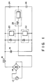
- Fig. 5 is a circuit diagram showing the fourth embodiment of a power source circuit according to the present invention.
- the two inductors 52 and 60 are omitted in the power source circuit shown in Fig. 2, and an inductor 96 is connected between a node between capacitors 48 and 50 and a node between reverse-conductive switches 74 and 76.
- a triangular-wave AC current flows through the inductor 96.
- a capacitor may be connected between the two terminals of the diode bridge 38 via the inrush current preventing circuit 46, as shown in Fig. 3.
- a capacitor may be connected between the two terminals of the diode bridge 38 via the inrush current preventing circuit 46, as shown in Fig. 4.
- the load 82 may be connected in parallel with the smoothing capacitor 56.
Landscapes
- Engineering & Computer Science (AREA)
- Power Engineering (AREA)
- Rectifiers (AREA)
- Inverter Devices (AREA)
- Circuit Arrangements For Discharge Lamps (AREA)
- Prepayment Telephone Systems (AREA)
Claims (6)
- Un circuit d'alimentation, comportant une source d'alimentation alternative (30), un redresseur pleine onde (38) relié à ladite source d'alimentation alternative (30) pour exécuter un redressement pleine onde, un condensateur de lissage (56) relié à une borne de sortie dudit redresseur pleine onde (38) dans un circuit série par l'intermédiaire respectivement d'une première et d'une seconde diodes (54,58), lesdites première et seconde diodes (54,58) ayant des polarités dans le sens passant par rapport à une sortie provenant dudit redresseur pleine onde (38), des premiers et seconds moyens de commutation (74,76) à conduction inverse, montés en parallèle avec ledit condensateur de lissage (56), lesdits premiers et seconds moyens de commutation (74,76) à conduction inverse étant montés en série l'un avec l'autre, et au moins deux condensateurs (48,50),
caractérisé en ce que
ledit circuit série comporte au surplus un premier et un second inducteurs (52,60), lesdits au moins deux condensateurs (48,50) étant montés en série entre lesdits premier et second inducteurs (52,60) et en parallèle audit redresseur pleine onde (38) pour former un circuit de fourniture de l'énergie emmagasinée desdits inducteurs (52, 60) audit condensateur de lissage (56) en concordance avec un fonctionnement alterné MARCHE/ARRET desdits premiers et seconds moyens de commutation (74,76) à conduction inverse. - Un circuit d'alimentation, comportant une source d'alimentation alternative (30), un redresseur pleine onde (38) relié à ladite source d'alimentation alternative (30) pour exécuter un redressement pleine onde, un condensateur de lissage (56) relié à une borne de sortie dudit redresseur pleine onde (38) dans un circuit série par l'intermédiaire respectivement d'une première et d'une seconde diodes (54,58), lesdites première et seconde diodes (54,58) ayant des polarités dans le sens passant par rapport à une sortie provenant dudit redresseur pleine onde (38), des premiers et seconds moyens de commutation (74,76) à conduction inverse, montés en parallèle avec ledit condensateur de lissage (56), lesdits premiers et seconds moyens de commutation (74,76) à conduction inverse étant montés en série l'un avec l'autre, un inducteur (96) et au moins deux condensateurs (48,50),
caractérisé en ce que
ledit inducteur (96) est monté entre au moins une borne de sortie dudit redresseur pleine onde (38) et un point intermédiaire entre lesdits premiers et seconds moyens de commutation (74,76) à conduction inverse ; et
lesdits au moins deux condensateurs (48,50) sont disposés en parallèle audit redresseur pleine onde (38) et prévus dans un-circuit en étoile avec ledit inducteur (96), pour former un circuit de fourniture de l'énergie emmagasinée dudit inducteur (96) audit condensateur de lissage (56) en concordance avec un fonctionnement alterné MARCHE/ARRET desdits premiers et seconds moyens de commutation (74,76) à conduction inverse. - Un circuit selon la revendication 1, caractérisé en ce qu'une tension continue dudit condensateur de lissage (56) est établie pour être supérieure à une tension alternative d'une charge, de manière à être reliée entre un point intermédiaire entre lesdits premiers et seconds moyens de commutation (74,76) à conduction inverse et ledit condensateur de lissage (56), et les valeurs desdits premier et second inducteurs (52,60) sont déterminées pour établir un mode discontinu de courant dans lequel une énergie emmagasinée est totalement déchargée d'une capacité de ladite charge pendant les phases MARCHE desdits premiers et seconds moyens de commutation (74, 76) à conduction inverse.
- Un circuit selon la revendication 1 ou 2, caractérisé en ce qu'il comporte au surplus un circuit (46) de prévention de courant de démarrage, relié à une borne de sortie dudit redresseur pleine onde (38) et comportant un thyristor (40) comportant une anode, une cathode et une gâchette, une résistance (42) montée en parallèle sur ledit thyristor (40) entre l'anode et la cathode de celui-ci, et une unité (44) de commande de gâchette, montée entre la gâchette et la cathode dudit thyristor pour commander la gâchette.
- Un circuit selon la revendication 1 ou 2, caractérisé en ce que lesdits premiers et seconds moyens de commutation (74,76) à conduction inverse sont constitués par un premier et un second transistors à effet de champ (62,64) montés en série et une troisième et une quatrième diodes (66,68) montées en parallèle sur lesdits premier et second transistors à effet de champ (62,64) dans des sens de blocage inverse par rapport à une sortie provenant dudit redresseur pleine onde (38).
- Un circuit selon la revendication 2, caractérisé en ce qu'une tension continue dudit condensateur de lissage (56) est établie pour être supérieure à une tension alternative d'une charge de manière à être reliée entre un point intermédiaire entre lesdits premiers et seconds moyens de commutation (74,76) à conduction inverse et ledit condensateur de lissage (56), et une valeur dudit inducteur (96) est déterminée pour établir un mode discontinu de courant dans lequel une énergie emmagasinée est totalement déchargée d'une capacité de ladite charge pendant des phases MARCHE desdits premiers et seconds moyens de commutation (74,76) à conduction inverse.
Applications Claiming Priority (2)
| Application Number | Priority Date | Filing Date | Title |
|---|---|---|---|
| JP21090/90 | 1990-01-31 | ||
| JP2021090A JP2929635B2 (ja) | 1990-01-31 | 1990-01-31 | 電源回路 |
Publications (3)
| Publication Number | Publication Date |
|---|---|
| EP0440245A2 EP0440245A2 (fr) | 1991-08-07 |
| EP0440245A3 EP0440245A3 (en) | 1991-11-21 |
| EP0440245B1 true EP0440245B1 (fr) | 1995-04-05 |
Family
ID=12045174
Family Applications (1)
| Application Number | Title | Priority Date | Filing Date |
|---|---|---|---|
| EP91101315A Expired - Lifetime EP0440245B1 (fr) | 1990-01-31 | 1991-01-31 | Circuit d'alimentation |
Country Status (5)
| Country | Link |
|---|---|
| US (1) | US5303140A (fr) |
| EP (1) | EP0440245B1 (fr) |
| JP (1) | JP2929635B2 (fr) |
| KR (1) | KR910015099A (fr) |
| DE (1) | DE69108586T2 (fr) |
Cited By (1)
| Publication number | Priority date | Publication date | Assignee | Title |
|---|---|---|---|---|
| US8253424B2 (en) | 2009-09-11 | 2012-08-28 | Sma Solar Technology Ag | Topology surveying a series of capacitors |
Families Citing this family (27)
| Publication number | Priority date | Publication date | Assignee | Title |
|---|---|---|---|---|
| US5408403A (en) * | 1992-08-25 | 1995-04-18 | General Electric Company | Power supply circuit with power factor correction |
| TW302591B (fr) * | 1993-06-24 | 1997-04-11 | Samsung Electronics Co Ltd | |
| DE4403908C1 (de) * | 1994-02-08 | 1995-11-02 | Heinzinger Electronic Gmbh | Gegentaktschaltstufe |
| US5719473A (en) * | 1994-03-11 | 1998-02-17 | Patent-Treuhand-Gelsellschaft F. Elektrische Gluehlampen Mbh | High frequency operating circuit with in-rush current protection for operation of discharge lamps |
| DE4408313A1 (de) * | 1994-03-11 | 1995-09-14 | Patent Treuhand Ges Fuer Elektrische Gluehlampen Mbh | Schaltungsanordnung zum Betrieb von Entladungslampen |
| US5568373A (en) * | 1994-07-28 | 1996-10-22 | Small; Kenneth T. | Tolerant power converter |
| US6118225A (en) * | 1994-08-22 | 2000-09-12 | U.S. Philips Corporation | High frequency discharge lamp operating circuit with resonant power factor correction circuit |
| JP3484863B2 (ja) * | 1995-03-29 | 2004-01-06 | 東芝ライテック株式会社 | 電源装置、放電灯点灯装置および照明装置 |
| EP0757511B1 (fr) * | 1995-07-31 | 2003-03-26 | STMicroelectronics S.r.l. | Circuit de démarrage, transistor MOS utilisant un tel circuit |
| US6002213A (en) * | 1995-10-05 | 1999-12-14 | International Rectifier Corporation | MOS gate driver circuit with analog input and variable dead time band |
| JP3239757B2 (ja) * | 1996-05-31 | 2001-12-17 | 富士電機株式会社 | 交流電流源回路 |
| US5994848A (en) * | 1997-04-10 | 1999-11-30 | Philips Electronics North America Corporation | Triac dimmable, single stage compact flourescent lamp |
| US5982159A (en) * | 1997-07-31 | 1999-11-09 | Philips Electronics North America Corporation | Dimmable, single stage fluorescent lamp |
| US6020688A (en) * | 1997-10-10 | 2000-02-01 | Electro-Mag International, Inc. | Converter/inverter full bridge ballast circuit |
| EP0913919B1 (fr) * | 1997-10-29 | 2003-05-07 | Kabushiki Kaisha Meidensha | Convertisseur de puissance |
| DE19937925A1 (de) * | 1999-08-11 | 2001-02-15 | Patent Treuhand Ges Fuer Elektrische Gluehlampen Mbh | Halbbrückenwechselrichter |
| ITMI991131A1 (it) * | 1999-05-21 | 2000-11-21 | St Microelectronics Srl | Architettura di pilotaggio a semi-ponte (half-bridge) autooscillante a frequenza variabile in particolare per carichi elettrici |
| US20040189555A1 (en) * | 2003-03-26 | 2004-09-30 | Capen Larry Stephen | Use of track lighting switching power supplies to efficiently drive LED arrays |
| JP5101881B2 (ja) * | 2006-02-24 | 2012-12-19 | 三菱電機株式会社 | 系統連系インバータ装置 |
| CA2756020A1 (fr) * | 2009-03-23 | 2010-09-30 | Koninklijke Philips Electronics N.V. | Circuit d'alimentation |
| US8975899B2 (en) | 2009-09-11 | 2015-03-10 | Sma Solar Technology Ag | Inverter device comprising a topology surveying a series of capacitors |
| US9131564B2 (en) * | 2011-07-29 | 2015-09-08 | Panasonic Intellectual Property Management Co., Ltd. | Lighting device and illumination apparatus using same |
| JP5565436B2 (ja) * | 2012-06-27 | 2014-08-06 | 株式会社デンソー | 昇圧装置 |
| CN103635001B (zh) * | 2012-08-27 | 2018-01-09 | 李顺华 | 一种高压钠灯用的lc电感电容镇流器 |
| US9787246B2 (en) * | 2014-03-15 | 2017-10-10 | Mitsubishi Electric Corporation | Motor drive control device, compressor, air-sending device, and air-conditioning apparatus |
| NL2025328B1 (en) * | 2020-04-10 | 2021-10-26 | Prodrive Tech Bv | Electrical power converter |
| CN113541081B (zh) * | 2021-07-14 | 2022-08-19 | 四川大学 | 一种基于晶闸管的无损单相防冰融冰控制设备 |
Family Cites Families (6)
| Publication number | Priority date | Publication date | Assignee | Title |
|---|---|---|---|---|
| AU555174B2 (en) * | 1981-09-18 | 1986-09-18 | Oy Helvar | Electronic ballast for a discharge lamp |
| GB2124042B (en) * | 1982-06-01 | 1986-10-01 | Control Logic | Reduction of harmonics in gas discharge lamp ballasts |
| JPS59128128A (ja) * | 1983-01-13 | 1984-07-24 | Matsushita Electric Works Ltd | 積載方法 |
| JPH0691750B2 (ja) * | 1983-01-14 | 1994-11-14 | 松下電工株式会社 | インバータ装置 |
| JPS6194569A (ja) * | 1984-10-12 | 1986-05-13 | Matsushita Electric Works Ltd | インバ−タ装置 |
| JP2677406B2 (ja) * | 1989-01-26 | 1997-11-17 | 松下電工株式会社 | 電源装置 |
-
1990
- 1990-01-31 JP JP2021090A patent/JP2929635B2/ja not_active Expired - Lifetime
-
1991
- 1991-01-30 US US07/647,649 patent/US5303140A/en not_active Expired - Fee Related
- 1991-01-31 EP EP91101315A patent/EP0440245B1/fr not_active Expired - Lifetime
- 1991-01-31 DE DE69108586T patent/DE69108586T2/de not_active Expired - Fee Related
- 1991-01-31 KR KR1019910001677A patent/KR910015099A/ko not_active Withdrawn
Cited By (1)
| Publication number | Priority date | Publication date | Assignee | Title |
|---|---|---|---|---|
| US8253424B2 (en) | 2009-09-11 | 2012-08-28 | Sma Solar Technology Ag | Topology surveying a series of capacitors |
Also Published As
| Publication number | Publication date |
|---|---|
| EP0440245A3 (en) | 1991-11-21 |
| KR910015099A (ko) | 1991-08-31 |
| US5303140A (en) | 1994-04-12 |
| DE69108586T2 (de) | 1995-08-17 |
| JPH03226276A (ja) | 1991-10-07 |
| JP2929635B2 (ja) | 1999-08-03 |
| EP0440245A2 (fr) | 1991-08-07 |
| DE69108586D1 (de) | 1995-05-11 |
Similar Documents
| Publication | Publication Date | Title |
|---|---|---|
| EP0440245B1 (fr) | Circuit d'alimentation | |
| US20080094860A1 (en) | Bidirectional battery power inverter | |
| US6108218A (en) | Switching power supply with power factor control | |
| US10356861B2 (en) | Constant output current LED driver | |
| JPH11243646A (ja) | 充電器用のコンバータ回路 | |
| US6031739A (en) | Two-stage, three-phase split boost converter with reduced total harmonic distortion | |
| US7184287B2 (en) | Rectifier clamping circuit with reverse energy recovery | |
| JP3681596B2 (ja) | 直流電源装置 | |
| US20050036339A1 (en) | Current/voltage converter arrangement | |
| US11205969B2 (en) | Inverter device configured to operate in a CCM and sequentially operate in buck and boost phases | |
| WO2008042069A2 (fr) | Circuit pour l'alimentation d'une lampe à décharge à haute intensité | |
| JP3430420B2 (ja) | 電源装置 | |
| EP1097611B1 (fr) | Circuit | |
| KR950001293Y1 (ko) | 전원회로(power source circuit) | |
| JP2000341967A (ja) | インバータ装置 | |
| JP7838911B2 (ja) | 電力変換装置 | |
| EP4199331B1 (fr) | Convertisseur hybride en mode commuté, son procédé de fonctionnement et système d'éclairage | |
| JP3417078B2 (ja) | インバータ装置 | |
| KR100490645B1 (ko) | 비절연형 무정전 전원공급 장치 | |
| JP3409582B2 (ja) | 電源装置 | |
| JP3177240B2 (ja) | 電源回路 | |
| JP3725378B2 (ja) | 単相昇降圧形高力率コンバータ | |
| WO2000067534A1 (fr) | Systeme de circuit | |
| JP3413966B2 (ja) | インバータ装置 | |
| JPH03226267A (ja) | 電源回路 |
Legal Events
| Date | Code | Title | Description |
|---|---|---|---|
| PUAI | Public reference made under article 153(3) epc to a published international application that has entered the european phase |
Free format text: ORIGINAL CODE: 0009012 |
|
| 17P | Request for examination filed |
Effective date: 19910225 |
|
| AK | Designated contracting states |
Kind code of ref document: A2 Designated state(s): DE GB |
|
| PUAL | Search report despatched |
Free format text: ORIGINAL CODE: 0009013 |
|
| AK | Designated contracting states |
Kind code of ref document: A3 Designated state(s): DE GB |
|
| 17Q | First examination report despatched |
Effective date: 19940308 |
|
| GRAA | (expected) grant |
Free format text: ORIGINAL CODE: 0009210 |
|
| AK | Designated contracting states |
Kind code of ref document: B1 Designated state(s): DE GB |
|
| REF | Corresponds to: |
Ref document number: 69108586 Country of ref document: DE Date of ref document: 19950511 |
|
| PLBE | No opposition filed within time limit |
Free format text: ORIGINAL CODE: 0009261 |
|
| STAA | Information on the status of an ep patent application or granted ep patent |
Free format text: STATUS: NO OPPOSITION FILED WITHIN TIME LIMIT |
|
| 26N | No opposition filed | ||
| REG | Reference to a national code |
Ref country code: GB Ref legal event code: 746 Effective date: 20011115 |
|
| REG | Reference to a national code |
Ref country code: GB Ref legal event code: IF02 |
|
| PGFP | Annual fee paid to national office [announced via postgrant information from national office to epo] |
Ref country code: GB Payment date: 20040128 Year of fee payment: 14 |
|
| PGFP | Annual fee paid to national office [announced via postgrant information from national office to epo] |
Ref country code: DE Payment date: 20040212 Year of fee payment: 14 |
|
| PG25 | Lapsed in a contracting state [announced via postgrant information from national office to epo] |
Ref country code: GB Free format text: LAPSE BECAUSE OF NON-PAYMENT OF DUE FEES Effective date: 20050131 |
|
| PG25 | Lapsed in a contracting state [announced via postgrant information from national office to epo] |
Ref country code: DE Free format text: LAPSE BECAUSE OF NON-PAYMENT OF DUE FEES Effective date: 20050802 |
|
| GBPC | Gb: european patent ceased through non-payment of renewal fee |
Effective date: 20050131 |