EP0441410B1 - Procedure to separate solid particles from liquid particles of a dental mixture - Google Patents
Procedure to separate solid particles from liquid particles of a dental mixture Download PDFInfo
- Publication number
- EP0441410B1 EP0441410B1 EP91103249A EP91103249A EP0441410B1 EP 0441410 B1 EP0441410 B1 EP 0441410B1 EP 91103249 A EP91103249 A EP 91103249A EP 91103249 A EP91103249 A EP 91103249A EP 0441410 B1 EP0441410 B1 EP 0441410B1
- Authority
- EP
- European Patent Office
- Prior art keywords
- centrifuge
- solids
- mixture
- liquid
- air
- Prior art date
- Legal status (The legal status is an assumption and is not a legal conclusion. Google has not performed a legal analysis and makes no representation as to the accuracy of the status listed.)
- Expired - Lifetime
Links
Images


Classifications
-
- A—HUMAN NECESSITIES
- A61—MEDICAL OR VETERINARY SCIENCE; HYGIENE
- A61C—DENTISTRY; APPARATUS OR METHODS FOR ORAL OR DENTAL HYGIENE
- A61C17/00—Devices for cleaning, polishing, rinsing or drying teeth, teeth cavities or prostheses; Saliva removers; Dental appliances for receiving spittle
- A61C17/06—Saliva removers; Accessories therefor
- A61C17/065—Saliva removers; Accessories therefor characterised by provisions for processing the collected matter, e.g. for separating solids or air
Definitions
- the invention relates to a method for separating a dental solid-liquid mixture which is fed to the inlet of a centrifuge, the solids being centrifuged out of the mixture and emptied after each centrifugation phase together with residual liquid under the action of gravity through the outlet of the centrifuge into a lower arranged collecting pot are, in which solids are collected, and from the residual liquid collecting above a predetermined solid deposition height is sucked up and returned to the centrifuge, in which solids still contained are centrifuged again, and wherein cleaned liquid is discharged into a discharge channel.
- the invention has now set itself the task of returning the residual liquid to be centrifuged so smoothly into the centrifuge that the liquid emerging from the centrifuge is very pure. This is achieved according to the invention in that the residual liquid with solids still present is returned to the inlet of the centrifuge via a line different from the outlet, it being first transferred from the collecting pot into a secondary container and then pumped from the secondary container into the inlet of the centrifuge.
- a preferred embodiment provides that in the centrifuge a mixture flowing in under normal pressure and a mixture supplied in a vacuum system and discharged therefrom by means of an auxiliary pump are separated together, the centrifuge and the collecting pot being provided outside the vacuum system, and that the solids containing solids Residual liquid is sucked into the mixture in the vacuum system.
- the centrifuge 80 of the separator is fed the solid-liquid mixture to be separated on the one hand by gravity from a bowl or the like, and on the other hand by the suction system from the patient's mouth.
- a housing 10, which is separated by a partition 11, which ends at a distance from the housing cover 4, is divided into a settling tank 1 and a secondary tank 2. Above both remains a common space, which is part of an air separation space 3, which is formed in an attachment 26.
- the deflection surface 33 widens from the inlet 7 towards the outer wall 19 of the housing 10.
- the settling tank 1 forms a removable collecting pot 6, which is pushed on from below and held in a sealing manner.
- the mixture flowing through the inlet 7 and the deflection surface 33 separates solids and liquid from the suction air, which collect in the settling container 1, through the deflection, the swirling and the impact on the outer wall 19. At the same time, this forms a calming zone for the deposition of the solids at the bottom of the collecting pot 6.
- the inflowing solid-liquid mixture displaces clarified liquid which still contains solids via a transfer device arranged above the maximum solids deposition level into the secondary tank 2, which can be of any type.
- a discontinuous liquid transfer is preferably provided by the suction lifter 20 shown, the longer leg 23 of which opens into the secondary container 2.
- the inlet opening of the shorter leg 22 is above the maximum deposit height and below the insertion edge of the collecting pot 6 and the overflow level of the suction lifter 20 is lower than the upper edge of the partition wall, from which a grid 79 is pulled up to cover 4.
- the secondary container 2 is surrounded by a further housing 72 and is provided with a liquid outlet 9, the outlet opening 63 of which is secured against the entry of false air by a check valve 50.
- the secondary container is emptied by means of an auxiliary pump 47 designed as an impeller pump, via a pipe section 45 standing up and the liquid outlet 9, the outlet opening 63 of which is formed laterally in the pump chamber 60 at a short distance above the bottom 64.
- the suction channel 46 of the auxiliary pump 47 is inserted, which has a base plate 66 with a central opening opening into the pump chamber.
- the housing 72 consists of an upper part 74 which accommodates the motor 53 of the auxiliary pump 47, the upper side 62 of which is aligned with the cover 4 and the cyclone 38 of the air separation space 3 is delimited at the bottom, a central part 75 and a lower part 76.
- the vertically running drive shaft 55 is in a bearing body 61 which is in a the motor receiving space from Intake duct 46 separating bottom 25 is inserted, protrudes through an enlarged portion of the intake duct 46 and is supported on the horizontal base plate 66 via support webs 95. From the enlarged part of the intake duct 46, an air line 71 leads through the pipe section 45 leading through the floor 25 back into the air separation space 3, which is separated from the secondary container 2 by a partition 78.
- the drive shaft 65 bears the curved impeller 59 of the auxiliary pump 47 directly below the opening in the base plate 66. Because of the check valve 50 which protects the outlet opening 63 against entry of false air, there is normal pressure below the bottom 64 separating the pump chamber 60 from the central part 75.
- the auxiliary pump 47 is switched as a function of the liquid level in the intake duct 46 and in the secondary tank 2, which is sensed by sensors 52, via the controller 54.
- the middle part 75 of the pump housing 72 receives a centrifuge inlet space 82, and is cylindrical so that it can be rotated into any position.
- the centrifuge inlet space 82 is also penetrated by the drive shaft 55, on which a centrifuge container 83 is arranged following the impeller 59 via supporting webs 91.
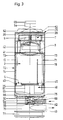
- a guide surface 86 which runs horizontally in the peripheral part and merges into a sleeve projecting coaxially with the drive shaft 55 into the centrifuge interior 90, an outlet line 89 (FIG. 3) of the bowl opens essentially tangentially.
- the centrifuge container 83 tapers downward to a bottom opening 84, through the centrifuged solids into the catcher 77 placed on the lower part 76, in which solids that flow away from the centrifuge 80 together with residual liquid when the centrifuge is at a standstill.
- the liquid rises in the centrifuge container 83 and passes through an inwardly projecting ring flange 85 into an outer ring channel 88 of the lower part 76, the ring channel towards the collecting bowl 77 being covered by an outer ring flange 87 of the centrifuge container 83.
- the cleaned liquid then flows out via the outlet channel 49 (FIG. 3), which, like the outlet line 89 of the bowl, can be rotated into any position. Since the collecting pot 77 usually has a limited capacity, which is less than that of the collecting pot 6 of the settling container 1, the collecting pot 77 is also connected via a line 81 to the mixture inlet 7, the inlet opening being covered by a sieve 65.
- the separator housing 10 can be separated from the upper part 74 of the housing 72 in a simple manner as soon as the attachment 26 has been removed.
- the two pipe pieces 45 also form push-on parts for the secondary container 2, which carries lateral pins 73 on the upper side, which can be inserted from above into slots in the side walls of the housing 72.
- the suction pipe 42 can be closed by a closure body 41 which is arranged on a rod 28 which projects centrally upward through the suction pipe 42 and which penetrates the upper cover 29 of the attachment 26 and has a head 93 there, between the cover 29 and the head 93 a compression spring 92 is arranged so that the closure body 41 is acted upon in the closing direction.
- the upper cover 29 delimits a chamber 30 in which a membrane 31 is arranged and is under vacuum via a line 32 which is connected to the clean air outlet 8.
- the membrane 31 acts on the head 93 and holds the closure body 41 in the open position.
- a valve 69 is inserted into the line 32 and is operated via a control 54, to which a liquid level sensor 68 is assigned. If the liquid in the housing 10 rises into the air separation chamber 3, the valve 69 is actuated via the level sensor 68, which connects the chamber 30 to the outside air, so that the closure body 41 closes the suction pipe 42 under the action of the spring 92.
- the suction pump itself is also advantageously switched off at the same time.
- a collecting trough 94 around the cyclone 38 collects residual liquid and guides it into the housing 10, preferably into the sub-tank 2 below.
Landscapes
- Health & Medical Sciences (AREA)
- Dentistry (AREA)
- Epidemiology (AREA)
- Life Sciences & Earth Sciences (AREA)
- Animal Behavior & Ethology (AREA)
- General Health & Medical Sciences (AREA)
- Public Health (AREA)
- Veterinary Medicine (AREA)
- Centrifugal Separators (AREA)
- Cyclones (AREA)
- Dental Preparations (AREA)
- Eye Examination Apparatus (AREA)
- Apparatus For Radiation Diagnosis (AREA)
- Dental Tools And Instruments Or Auxiliary Dental Instruments (AREA)
- Display Devices Of Pinball Game Machines (AREA)
- Toys (AREA)
- Acyclic And Carbocyclic Compounds In Medicinal Compositions (AREA)
- Separation Using Semi-Permeable Membranes (AREA)
- Vaporization, Distillation, Condensation, Sublimation, And Cold Traps (AREA)
Abstract
Description
Die Erfindung betrifft ein verfahren zur Trennung eines dentalen Feststoff-Flüssigkeitsgemisches, das dem Einlaß einer Zentrifuge zugeführt wird, wobei die Feststoffe aus dem Gemisch abzentrifugiert und nach jeder Zentrifugierphase gemeinsam mit Restflüssigkeit unter Einwirkung von Schwerkraft durch den Auslaß der Zentrifuge in einen tiefer angeordneten Auffangtopf entleert werden, in dem Feststoffe gesammelt werden, und aus dem sich oberhalb einer vorgegebenen Feststoffablagerungshöhe sammelnde Restflüssigkeit nach oben abgesaugt und wieder der Zentrifuge zugeführt wird, in der noch enthaltene Feststoffe neuerlich abzentrifugiert werden, und wobei gereinigte Flüssigkeit in einen Ablaufkanal ausgetragen wird.The invention relates to a method for separating a dental solid-liquid mixture which is fed to the inlet of a centrifuge, the solids being centrifuged out of the mixture and emptied after each centrifugation phase together with residual liquid under the action of gravity through the outlet of the centrifuge into a lower arranged collecting pot are, in which solids are collected, and from the residual liquid collecting above a predetermined solid deposition height is sucked up and returned to the centrifuge, in which solids still contained are centrifuged again, and wherein cleaned liquid is discharged into a discharge channel.
Ein derartiges Verfahren, sowie eine Einrichtung zu dessen Durchführung sind der DE-A-30 30 614 zu entnehmen. Die Feststoffe fließen dort bei Stillstand der Zentrifuge unter Schwerkrafteinwirkung durch einen an der Unterseite der Zentrifuge angeordneten Auslaßstutzen aus und werden in einem Absetzbehälter aufgefangen, in den der Auslaßstutzen ragt. Da die Zentrifuge aufgrund der Zentrifugalkräfte auch als Pumpe wirkt, wird zu Beginn jeder weiteren Zentrifugierphase die sich oberhalb der sedimentierenden Feststoffe sammelnde Restflüssigkeit durch den Auslaßstutzen in die Zentrifuge zurückgesaugt, wodurch ein maximales Flüssigkeitsniveau nie überschritten wird. Die Sedimentation der Feststoffe wird dabei trotz im Absetzbehälter angeordneter Beruhigungsflügel bei jeder Rücksaugung der Restflüssigkeit durch den mitrotierenden Auslaßstutzen empfindlich gestört. Teile der abgeschiedenen Feststoffe werden wieder mitgerissen, die in der Zentrifuge wieder abzentrifugiert werden, neuerlich in den Absetzbehälter abfließen, und so zwischen der Zentrifuge und dem Absetzbehälter hin- und hertransportiert werden.Such a method and a device for carrying it out can be found in DE-A-30 30 614. When the centrifuge is stopped, the solids flow out under gravity through an outlet nozzle arranged on the underside of the centrifuge and are collected in a settling container into which the outlet nozzle protrudes. Since the centrifuge also acts as a pump due to the centrifugal forces, the residual liquid collecting above the sedimenting solids is sucked back into the centrifuge through the outlet nozzle at the beginning of each further centrifugation phase, whereby a maximum liquid level is never exceeded. The sedimentation of the solids is severely disrupted by the co-rotating outlet nozzle despite the calming vanes arranged in the settling tank each time the residual liquid is sucked back. Parts of the separated solids are carried away again, which are centrifuged off again in the centrifuge, again in the settling tank drain off, and so be transported back and forth between the centrifuge and the settling tank.
Die Erfindung hat es sich nun zur Aufgabe gestellt, die neuerlich zu zentrifugierende Restflüssigkeit so störungsfrei in die Zentrifuge zurückzuführen, daß die von der Zentrifuge austretende Flüssigkeit sehr rein ist. Erfindungsgemäß wird dies dadurch erreicht, daß die Restflüssigkeit mit noch enthaltenen Feststoffen zum Einlaß der Zentrifuge über eine vom Auslaß verschiedene Leitung zurückgeführt wird, wobei sie zuerst aus dem Auffangtopf in einen Nebenbehälter übergeleitet und dann aus dem Nebenbehälter in den Einlaß der Zentrifuge gepumpt wird.The invention has now set itself the task of returning the residual liquid to be centrifuged so smoothly into the centrifuge that the liquid emerging from the centrifuge is very pure. This is achieved according to the invention in that the residual liquid with solids still present is returned to the inlet of the centrifuge via a line different from the outlet, it being first transferred from the collecting pot into a secondary container and then pumped from the secondary container into the inlet of the centrifuge.
Beim erfindungsgemäßen Verfahren erfolgt somit keine direkte Rücksaugung der feststoffbeladenen Restflüssigkeit durch den Auslaß der Zentrifuge. Es entfällt eine Durchwirbelung bei der Entnahme der Restflüssigkeit, da kein rotierender Teil in die Restflüssigkeit eintaucht.In the method according to the invention, there is therefore no direct suction of the residual liquid laden with solids through the outlet of the centrifuge. There is no swirling when removing the residual liquid, since no rotating part is immersed in the residual liquid.
Eine bevorzugte Ausführung sieht dabei vor, daß in der Zentrifuge ein unter Normaldruck zufließendes sowie ein in einem Unterdrucksystem zugeführtes und daraus mittels einer Hilfspumpe ausgetragenes Gemisch gemeinsam getrennt werden, wobei die Zentrifuge und der Auffangtopf außerhalb des Unterdrucksystems vorgesehen werden, und daß die noch Feststoffe enthaltende Restflüssigkeit aus dem Auffangtopf in das im Unterdrucksystem zugeführte Gemisch eingesaugt wird.A preferred embodiment provides that in the centrifuge a mixture flowing in under normal pressure and a mixture supplied in a vacuum system and discharged therefrom by means of an auxiliary pump are separated together, the centrifuge and the collecting pot being provided outside the vacuum system, and that the solids containing solids Residual liquid is sucked into the mixture in the vacuum system.
Dadurch kann ein Gemisch, das beispielsweise gemäß der DE-A-32 31 272 zum einen aus einer Speischale und zum anderen aus einem mit einer Luftsaugpumpe in Verbindung stehenden Saughandstück stammt, gemeinsam bzw. gleichzeitig getrennt werden, wobei für die Absaugung der im Auffangtopf noch Feststoffe enthaltenden Restflüssigkeit die Saugpumpe der Absauganlage verwendet wird.This allows a mixture, for example, according to DE-A-32 31 272 on the one hand from a bowl and on the other another comes from a suction handpiece connected to an air suction pump, can be separated together or at the same time, the suction pump of the suction system being used for the suction of the residual liquid which still contains solids in the collecting pot.
Nachstehend wird nun das Verfahren an Hand der beiliegenden Zeichnungen näher beschrieben. Darin zeigen:
- Fig.1
- einen Vertikalschnitt durch einen Abscheider nach der Linie I-I der Fig. 2 und
- Fig.2 und 3
- Schnitte nach den Linien II-II und III-III der Fig. 1.
- Fig. 1
- a vertical section through a separator along the line II of Fig. 2 and
- Fig. 2 and 3
- Cuts along lines II-II and III-III of Fig. 1st
Der Zentrifuge 80 des Abscheiders wird das zu trennende Feststoff-Flüssigkeitsgemisch einerseits durch Schwerkraft aus einer Speischale oder dergleichen, andererseits durch die Absauganlage aus dem Mund des Patienten zugeführt. Ein Gehäuse 10, das durch eine Trennwand 11, die mit Abstand zur Gehäuseabdeckung 4 endet, ist in einen Absetzbehälter 1 und einen Nebenbehälter 2 unterteilt. Oberhalb beider verbleibt ein gemeinsamer Raum, der Teil eines Luftabscheideraumes 3 ist, der in einem Aufsatz 26 ausgebildet ist. Oberhalb des Absetzbehälters 1 ist ein Einlaß 7 für das von einem zahnärztlichen Saughandstück kommende Feststoff-Flüssigkeits-Saugluftgemisch vorgesehen, wobei diesem eine erste Umlenkfläche 33 zugeordnet ist, sodaß der Endteil des Einlasses etwa U-förmig ausgebildet ist. Die Umlenkfläche 33 erweitert sich vom Einlaß 7 aus in der Breite zur Außenwand 19 des Gehäuses 10 hin. Der Absetzbehälter 1 bildet einen abnehmbaren Sammeltopf 6, der von unten aufgeschoben und dichtend gehalten ist. Das durch den Einlaß 7 und die Umlenkfläche 33 strömende Gemisch trennt durch die Umlenkung, die Verwirbelung und den Aufprall an die Außenwand 19 Feststoffe und Flüssigkeit von der Saugluft ab, die sich im Absetzbehälter 1 sammeln. Dieser bildet gleichzeitig eine Beruhigungszone für die Ablagerung der Feststoffe am Boden des Sammeltopfes 6. Mit Erreichen einer bestimmten Füllhöhe der Flüssigkeit im Absetzbehälter 1 verdrängt weiter zufließendes Feststoff-Flüssigkeitsgemisch geklärte, jedoch noch Feststoffe enthaltende Flüssigkeit über eine oberhalb des maximalen Feststoffablagerungsniveaus angeordnete Übertrittseinrichtung in den Nebenbehälter 2, die beliebiger Art sein kann. Vorzugsweise ist ein diskontinuierlicher Flüssigkeitsübertritt durch den gezeigten Saugheber 20 vorgesehen, dessen längerer Schenkel 23 im Nebenbehälter 2 mündet. Die Eintrittsöffnung des kürzeren Schenkels 22 liegt dabei oberhalb der maximalen Ablagerungshöhe und unterhalb des Einsteckrandes des Sammeltopfes 6 und das Überlaufniveau des Saughebers 20 liegt tiefer als der obere Rand der Trennwand, von dem ein Gitter 79 zur Abdeckung 4 hochgezogen ist. Der Nebenbehälter 2 ist von einem weiteren Gehäuse 72 umgeben und mit einem Flüssigkeitsauslaß 9 versehen, dessen Austrittsöffnung 63 gegen den Eintritt von Falschluft durch ein Rückschlagventil 50 gesichert ist.The centrifuge 80 of the separator is fed the solid-liquid mixture to be separated on the one hand by gravity from a bowl or the like, and on the other hand by the suction system from the patient's mouth. A
Die Entleerung des Nebenbehälters erfolgt mittels einer als Flügelradpumpe ausgebildeten Hilfspumpe 47 über ein hochstehendes Rohrstück 45 und den Flüssigkeitsauslaß 9, dessen Austrittsöffnung 63 mit geringem Abstand oberhalb des Bodens 64 seitlich in der Pumpenkammer 60 ausgebildet ist. In diese ist der Ansaugkanal 46 der Hilfspumpe 47 eingesetzt, der eine Bodenplatte 66 mit einer in die Pumpenkammer mündenden mittleren Öffnung aufweist. Das Gehäuse 72 besteht aus einem den Motor 53 der Hilfspumpe 47 aufnehmenden Oberteil 74, dessen Oberseite 62 mit der Abdeckung 4 fluchtet und den Zyklon 38 des Luftabscheideraumes 3 nach unten begrenzt, einem Mittelteil 75 und einem Unterteil 76. Die vertikal verlaufende Antriebswelle 55 ist in einem Lagerkörper 61 gelagert, der in einen den Motoraufnahmeraum vom Ansaugkanal 46 trennenden Boden 25 eingesetzt ist, durch einen erweiterten Abschnitt des Ansaugkanals 46 ragt und an der horizontalen Bodenplatte 66 über Stützstege 95 abgestützt ist. Vom erweiterten Teil des Ansaugkanals 46 führt eine Luftleitung 71 durch das durch den Boden 25 führende Rohrstück 45 zurück in den Luftabscheideraum 3, wobei diese durch eine Trennwand 78 vom Nebenbehälter 2 abgeteilt ist. Die Antriebswelle 65 trägt direkt unterhalb der Öffnung in der Bodenplatte 66 das gekrümmte Leitflächen aufweisende Flügelrad 59 der Hilfspumpe 47. Aufgrund des die Austrittsöffnung 63 gegen Falschlufteintritt sichernden Rückschlagventils 50 ist unterhalb des die Pumpenkammer 60 vom Mittelteil 75 trennenden Bodens 64 Normaldruck gegeben. Die Hilfspumpe 47 wird in Abhängigkeit vom Flüssigkeitsstand im Ansaugkanal 46 und im Nebenbehälter 2, der von Fühlern 52 abgetastet wird, über die Steuerung 54 geschaltet.The secondary container is emptied by means of an
Der Mittelteil 75 des Pumpengehäuses 72 nimmt einen Zentrifugeneintrittsraum 82 auf, und ist zylindrisch ausgebildet, sodaß er in jede beliebige Stellung verdreht werden kann. Der Zentrifugeneintrittsraum 82 ist ebenfalls von der Antriebswelle 55 durchsetzt, auf der im Anschluß an das Flügelrad 59 über Stützstege 91 ein Zentrifugenbehälter 83 angeordnet ist.In den Zentrifugeneintrittsraum 82, der nach unten durch eine Leitfläche 86 begrenzt ist, die im peripheren Teil horizontal verläuft und in eine mit der Antriebswelle 55 koaxiale in den Zentrifugeninnenraum 90 ragende Hülse übergeht, mündet im wesentlichen tangential eine Ablaufleitung 89 (Fig. 3) der Speischale. Das im Zentrifugeneintrittsraum 82 sich aus der Ablaufleitung 89 und der Austrittsöffnung 63 vereinigende Gemisch fließt in die Zentrifuge 80, die im nachfolgenden Unterteil 76 des Pumpengehäuses ausgebildet ist. Der Zentrifugenbehälter 83 verjüngt sich nach unten zu einer Bodenöffnung 84, durch die abzentrifugierte Feststoffe in den auf den Unterteil 76 aufgesetzten Auffangtopf 77 gelangen, in dem sich aus der Zentrifuge 80 bei deren Stillstand gemeinsam mit Restflüssigkeit abfließende Feststoffe absetzen. Die Flüssigkeit steigt hingegen im Zentrifugenbehälter 83 nach oben und tritt über einen nach innen abstehenden Ringflansch 85 in einen äußeren Ringkanal 88 des Unterteiles 76, wobei der Ringkanal zum Auffangtopf 77 hin durch einen äußeren Ringflansch 87 des Zentrifugenbehälters 83 abgedeckt ist. Die gereinigte Flüssigkeit fließt dann über den Ablaufkanal 49 (Fig. 3) ab, der ebenso wie die Ablaufleitung 89 der Speischale in jede beliebige Stellung verdrehbar ist. Da der Auffangtopf 77 meist ein begrenztes Fassungsvermögen aufweist, das geringer als das des Sammeltopfes 6 des Absetzbehälters 1 ist, ist weiters der Auffangtopf 77 über eine Leitung 81 mit dem Gemischeinlaß 7 verbunden, wobei die Eintrittsöffnung durch ein Sieb 65 überdeckt ist. Der in der Zentrifuge 80 abgeschiedene überschüssige Feinschlamm wird somit in den Gemischeinlaß 7 zurückgesaugt, und verbleibt zu einem Teil im Absetzbehälter 1. Reste der Feststoffe werden mit der Restflüssigkeit in der bereits beschriebenen Weise wieder in den Zentrifugeneintrittsraum 82 mit Hilfe der Hilfspumpe 47 ausgetragen.The
Das Abscheidegehäuse 10 ist vom Oberteil 74 des Gehäuses 72 in einfacher Weise trennbar, sobald der Aufsatz 26 abgenommen ist. Die beiden Rohrstücke 45 bilden auch Aufsteckteile für den Nebenbehälter 2, der an der Oberseite seitliche Stifte 73 trägt, die von oben in Schlitze der Seitenwände des Gehäuses 72 einsetzbar sind.The
Die von den Feststoffen und der Flüssigkeit befreite Luft wird entlang eines in Verlängerung der Trennwand 11 in den Aufsatz 26 sich erstreckenden Wandabschnittes 27 nach oben, in einer Schraubenlinie eines Zyklons 38 um ein zentrales Absaugrohr 42 nach unten, sodann an dessen Ende durch das Absaugrohr 42 wieder nach oben und schließlich durch den Reinluftauslaß 8 zur Saugpumpe gesagt. Das Absaugrohr 42 ist durch einen Verschlußkörper 41 verschließbar, der an einem zentral durch das Absaugrohr 42 nach oben ragenden Stab 28 angeordnet ist, der die obere Abdeckung 29 des Aufsatzes 26 durchsetzt und dort einen Kopf 93 aufweist, wobei zwischen der Abdeckung 29 und dem Kopf 93 eine Druckfeder 92 angeordnet ist, sodaß der Verschlußkörper 41 in Schließrichtung beaufschlagt ist. Die obere Abdeckung 29 begrenzt eine Kammer 30, in der eine Membran 31 angeordnet ist, und über eine Leitung 32, die an den Reinluftauslaß 8 angeschlossen ist, unter Unterdruck steht. Dadurch beaufschlagt die Membran 31 den Kopf 93 und hält den Verschlußkörper 41 in Offenstellung. In die Leitung 32 ist ein Ventil 69 eingesetzt, das über eine Steuerung 54 betätigt wird, der ein Flüssigkeitsniveaufühler 68 zugeordnet ist. Steigt die Flüssigkeit im Gehäuse 10 in den Luftabscheideraum 3 an, so wird über den Niveaufühler 68 das Ventil 69 betätigt, das die Kammer 30 mit der Außenluft in Verbindung setzt, sodaß unter Wirkung der Feder 92 der Verschlußkörper 41 das Absaugrohr 42 verschließt. Vorteilhaft wird dabei gleichzeitig auch die Saugpumpe selbst abgeschaltet. Eine Auffangrinne 94 rund um den Zyklon 38 sammelt Restflüssigkeit und leitet diese ins Gehäuse 10 vorzugsweise in den darunter liegenden Nebenbehälter 2.The air freed from the solids and the liquid flows along a wall section extending into the
Claims (2)
- A method of separating a dental solid-liquid mixture which is fed to the inlet (82) of a centrifuge (80), wherein the solids are centrifuged out of the mixture and emptied through the outlet (84) of the centrifuge (80) after each centrifuging phase jointly with residual liquid under the effect of the force of gravity into a lower receiving container (77) in which solids are collected and from which residual liquid which accumulates above a predetermined settling level of solids is sucked off upwardly and fed again to the centrifuge (80) in which solids still contained therein are again centrifuged, and wherein purified liquid is discharged into a drain duct (49), characterised in that the residual liquid, jointly with the solids still contained therein, is fed back to the inlet (82) of the centrifuge (80) by way of a conduit (81) different from the outlet (84), whereby it firstly is transferred from the receiving container (77) into a secondary container (2) and then pumped from the secondary container (2) into the inlet (82) of the centrifuge (80).
- A method according to claim 1, characterised in that a mixture flowing to the centrifuge under normal pressure and a mixture which is supplied in a reduced pressure system and which is discharged therefrom by means of an auxiliary pump (47) are jointly separated in the centrifuge (80), wherein the centrifuge (80) and the receiving container (77) are provided outside the reduced pressure system, and that the residual liquid, jointly with the solids still contained therein, is sucked from the receiving container (77) into the mixture which is supplied by the reduced pressure system.
Applications Claiming Priority (3)
| Application Number | Priority Date | Filing Date | Title |
|---|---|---|---|
| AT3986/84 | 1984-12-17 | ||
| AT398684 | 1984-12-17 | ||
| EP86900003A EP0242358B1 (en) | 1984-12-17 | 1985-12-16 | Method of separation of a dental solid-liquid mixture |
Related Parent Applications (1)
| Application Number | Title | Priority Date | Filing Date |
|---|---|---|---|
| EP86900003.4 Division | 1986-07-08 |
Publications (2)
| Publication Number | Publication Date |
|---|---|
| EP0441410A1 EP0441410A1 (en) | 1991-08-14 |
| EP0441410B1 true EP0441410B1 (en) | 1996-02-28 |
Family
ID=3558107
Family Applications (4)
| Application Number | Title | Priority Date | Filing Date |
|---|---|---|---|
| EP91103249A Expired - Lifetime EP0441410B1 (en) | 1984-12-17 | 1985-12-16 | Procedure to separate solid particles from liquid particles of a dental mixture |
| EP91103248A Expired - Lifetime EP0433270B1 (en) | 1984-12-17 | 1985-12-16 | Separator and procedure to separate solid particles from a solid-air mixture |
| EP91103247A Expired - Lifetime EP0432142B1 (en) | 1984-12-17 | 1985-12-16 | Dental separator |
| EP86900003A Expired - Lifetime EP0242358B1 (en) | 1984-12-17 | 1985-12-16 | Method of separation of a dental solid-liquid mixture |
Family Applications After (3)
| Application Number | Title | Priority Date | Filing Date |
|---|---|---|---|
| EP91103248A Expired - Lifetime EP0433270B1 (en) | 1984-12-17 | 1985-12-16 | Separator and procedure to separate solid particles from a solid-air mixture |
| EP91103247A Expired - Lifetime EP0432142B1 (en) | 1984-12-17 | 1985-12-16 | Dental separator |
| EP86900003A Expired - Lifetime EP0242358B1 (en) | 1984-12-17 | 1985-12-16 | Method of separation of a dental solid-liquid mixture |
Country Status (7)
| Country | Link |
|---|---|
| US (1) | US5018971A (en) |
| EP (4) | EP0441410B1 (en) |
| AT (4) | ATE134496T1 (en) |
| AU (1) | AU5311886A (en) |
| CA (1) | CA1293455C (en) |
| DE (6) | DE3584636D1 (en) |
| WO (1) | WO1986003669A1 (en) |
Families Citing this family (42)
| Publication number | Priority date | Publication date | Assignee | Title |
|---|---|---|---|---|
| DE3633494C2 (en) * | 1986-10-02 | 1995-04-27 | Duerr Dental Gmbh Co Kg | Device for separating fine solid particles, in particular amalgam particles, from waste water |
| EP0290745B1 (en) * | 1987-05-13 | 1990-07-18 | Siemens Aktiengesellschaft | Apparatus for separating solids from liquids for dental use |
| CH675549A5 (en) * | 1987-10-31 | 1990-10-15 | Emda | |
| AT389236B (en) * | 1987-11-03 | 1989-11-10 | Trawoeger Werner | SEPARATOR |
| AT388285B (en) * | 1987-11-20 | 1989-05-26 | Trawoeger Werner | SEPARATOR |
| ATA209688A (en) * | 1988-08-25 | 1989-10-15 | Trawoeger Werner | METHOD AND DEVICE FOR STOPPING FUNCTIONAL FAILURES OF A DENTAL SUCTION SYSTEM |
| US5032260A (en) * | 1988-12-20 | 1991-07-16 | Air Techniques Incorporated | Eductor system for water ring vacuum pump |
| US4919826A (en) * | 1988-12-20 | 1990-04-24 | Air Techniques, Incorporated | Process and apparatus for separating solids and liquids from an effluent stream |
| SE469681B (en) * | 1991-02-07 | 1993-08-23 | Boliden Contech Ab | MEASURES TO REDUCE RISKS CAUSING MERCURY SILVER DAMAGES IN CONNECTION WITH DENTAL TREATMENT |
| AT395941B (en) * | 1991-04-12 | 1993-04-26 | Trawoeger Werner | SEPARATOR FOR SEPARATING A SOLID-LIQUID MIXTURE |
| AT394952B (en) * | 1991-04-12 | 1992-08-10 | Trawoeger Werner | SEPARATOR FOR SEPARATING A SOLID-LIQUID MIXTURE |
| DE4117479A1 (en) * | 1991-05-28 | 1992-12-03 | Eitenmueller Klaus | EMPTYABLE SEDIMENT VESSEL AND METHOD FOR EMPTYING A SEDIMENT VESSEL |
| DE4143625B4 (en) * | 1991-07-03 | 2006-12-21 | Dürr Dental GmbH & Co. KG | separation unit |
| IT1259318B (en) * | 1992-02-19 | 1996-03-11 | Cattani Spa | SOLID PARTICLE SEPARATOR FOR CARRYING VARIABLES OF DISCHARGE FLUIDS OF DENTAL IMPLANTS |
| US5428256A (en) * | 1992-12-08 | 1995-06-27 | Schloss Engineering Equipment, Inc. | Submersible motor enclosure |
| DE4243239A1 (en) * | 1992-12-19 | 1994-06-23 | Schwarz Joerg Martin Dr | Amalgam separation system |
| AT399457B (en) * | 1993-01-22 | 1995-05-26 | Trawoeger Werner | DENTAL SEPARATOR |
| WO1994018903A1 (en) * | 1993-02-18 | 1994-09-01 | Trawoeger Werner | Process and separator for removing conveying suction air from a conveyed medium |
| AT400512B (en) * | 1993-11-19 | 1996-01-25 | Trawoeger Werner | Separator |
| AT400393B (en) * | 1993-11-05 | 1995-12-27 | Trawoeger Werner | SEPARATOR |
| US5667382A (en) * | 1994-05-27 | 1997-09-16 | Holland; Robert S. | Vacuum pump seal-water recycling and waste disposal system for dental operatories |
| DE4420723A1 (en) * | 1994-06-15 | 1995-12-21 | Duerr Dental Gmbh Co Kg | Device for removing solid particles from a working fluid |
| AT401228B (en) * | 1995-02-09 | 1996-07-25 | Trawoeger Werner | Separator |
| US5788852A (en) * | 1997-04-18 | 1998-08-04 | Mescon; Howard Michael | Process for preventing accumulation of contaminants in dental suction systems |
| AT405366B (en) * | 1997-05-05 | 1999-07-26 | Pregenzer Bruno | SUCTION DEVICE FOR A FLOWABLE MEDIUM |
| US6083306A (en) * | 1999-01-19 | 2000-07-04 | Cattani S.P.A. | Separator and discharger device for waste fluids in dental aspiration apparatus |
| US6083391A (en) * | 1999-05-20 | 2000-07-04 | Pregenzer; Bruno | Dental separator |
| US6276936B1 (en) | 1999-09-30 | 2001-08-21 | Michael Forster | Dental separator for solids from a solids/liquid mixture |
| US7306460B2 (en) * | 2001-06-25 | 2007-12-11 | Henry Hubner | Dental vacuum system assembly and process incorporating an amalgam separation chamber |
| US6790038B2 (en) * | 2001-06-25 | 2004-09-14 | Air Techniques, Inc. | Dental vacuum system assembly and process incorporating an amalgam separation chamber |
| CA2534082A1 (en) * | 2003-10-01 | 2005-04-14 | Ada Technologies, Inc. | System for removing mercury and mercuric compounds from dental wastes |
| FR2877208B1 (en) * | 2004-10-28 | 2007-02-23 | Joseph Ohayon | ORAL HYGIENE APPARATUS AND DISPOSABLE ASSEMBLY |
| US20070172790A1 (en) * | 2006-01-26 | 2007-07-26 | Midmark Corporation | Dental Vacuum System |
| KR100746529B1 (en) * | 2006-10-10 | 2007-08-06 | 주식회사 지피코 | Dental Contaminant Sterilizer |
| DE102006058955B4 (en) * | 2006-12-12 | 2014-07-24 | DüRR DENTAL AG | Suction device for dental, medical and industrial purposes |
| DE202010010802U1 (en) | 2010-07-29 | 2011-11-02 | DüRR DENTAL AG | solids |
| US11963836B2 (en) | 2016-10-12 | 2024-04-23 | Solmetex Llc | Detachable recycling container |
| US10646313B2 (en) | 2016-10-12 | 2020-05-12 | Solmetex, L.L.C. | Dental amalgam separation and recycling system |
| US10779923B2 (en) | 2016-10-12 | 2020-09-22 | Solmetex, L.L.C. | Detachable recycling container |
| US11660175B2 (en) | 2016-05-23 | 2023-05-30 | Solmetex, Llc | Detachable recycling container |
| AT523129B1 (en) * | 2019-11-08 | 2022-07-15 | Pregenzer Bruno | dental separator |
| AT524360B1 (en) * | 2020-11-02 | 2023-01-15 | Pregenzer Bruno | Separator with integrated sealing element for liquid-air separation |
Family Cites Families (38)
| Publication number | Priority date | Publication date | Assignee | Title |
|---|---|---|---|---|
| GB496998A (en) * | 1937-03-10 | 1938-12-12 | Erkensator G M B H | Improvements in and relating to centrifuges |
| US2759476A (en) * | 1954-12-08 | 1956-08-21 | Gomco Surgical Mfg Corp | Aspirating apparatus |
| US3051175A (en) * | 1960-02-29 | 1962-08-28 | Ritter Co Inc | Dental waste disposal system |
| US3078579A (en) * | 1960-10-28 | 1963-02-26 | Pelton & Crane Company | Dental aspirator with splash baffle |
| US3138873A (en) * | 1961-09-08 | 1964-06-30 | Harold P Bishop | Vacuum attachment for dental aspirator unit |
| GB1106858A (en) * | 1965-11-01 | 1968-03-20 | Electrolux Ab | Aspirator apparatus for dental purposes |
| GB1220255A (en) * | 1967-06-07 | 1971-01-27 | Chirana Zd Y Zdravotnicke Tech | Improvements in or relating to suction devices |
| US3665682A (en) * | 1970-08-06 | 1972-05-30 | Pennwalt Corp | Dental evacuation apparatus |
| US3847573A (en) * | 1971-03-10 | 1974-11-12 | S Gandrud | Dental office system |
| SE375701B (en) * | 1972-08-23 | 1975-04-28 | B I F Ritzler | |
| US3777403A (en) * | 1972-09-18 | 1973-12-11 | J Ritchie | Dental silver retrieval apparatus |
| US3861584A (en) * | 1973-06-20 | 1975-01-21 | Donaldson Co Inc | Self-purging centrifuge |
| DE2459881B2 (en) * | 1974-12-18 | 1979-04-12 | Siemens Ag, 1000 Berlin Und 8000 Muenchen | Dental device with a suction device |
| DE2713321C2 (en) * | 1977-03-25 | 1987-02-26 | Dürr-Dental GmbH & Co KG, 7120 Bietigheim-Bissingen | Method and device for separating liquid and solid components from the suction media mixture coming from the mouth of a patient |
| IT1124255B (en) * | 1979-01-15 | 1986-05-07 | Augusto Cattani & C Sas Off | SEPARATOR AND LIQUID DISCHARGE DEVICE FOR FLUID SUCTION SYSTEMS, IN PARTICULAR FOR PLANTS FOR CABINETS ODONTO IATRICI |
| SE427988B (en) * | 1979-03-08 | 1983-05-30 | Bjorn Ekman | Arrangement for separating of heavy metals from drain water, preferably in dental offices |
| US4234325A (en) * | 1979-03-19 | 1980-11-18 | Dresser Industries, Inc. | Silencer-separator with internal trap for liquid seal blowers or the like |
| DE2929804C2 (en) * | 1979-07-23 | 1985-10-03 | Siemens AG, 1000 Berlin und 8000 München | Dental suction device |
| SE440071B (en) * | 1979-08-17 | 1985-07-15 | Scania Dental | Centrifuge type apparatus for separating solid particles from the waste water |
| US4332560A (en) * | 1980-03-10 | 1982-06-01 | Rait Joseph M | Particle collector for use with dental suction apparatus |
| US4385891A (en) * | 1981-04-09 | 1983-05-31 | Ligotti Eugene F | Dental apparatus for preventing loss of precious metal particles |
| DE3145838A1 (en) * | 1981-11-19 | 1983-05-26 | Siemens AG, 1000 Berlin und 8000 München | "DENTAL SUCTION UNIT" |
| DK156880C (en) * | 1982-02-05 | 1990-03-12 | Horn Lassen Hans | APPARATUS FOR SEPARATION OF WASTE MATERIALS FROM A CURRENT OF LIQUID AND GAS |
| SE8203454L (en) * | 1982-06-04 | 1983-12-05 | Ernryd Leif Ab | DEVICE FOR Separation of solid particles from a liquid |
| DE3231272A1 (en) * | 1982-08-23 | 1984-02-23 | Siemens AG, 1000 Berlin und 8000 München | DENTAL SUCTION UNIT |
| DE3242212A1 (en) * | 1982-11-15 | 1984-05-17 | Siemens AG, 1000 Berlin und 8000 München | DENTAL SUCTION UNIT |
| DD232437A5 (en) * | 1983-05-17 | 1986-01-29 | Johann Renneberg | METHOD AND APPARATUS FOR TREATING GASES AND DUST |
| DE8314829U1 (en) * | 1983-05-19 | 1983-10-06 | Jerzy, Ingo, 2056 Glinde | GRAVITY SEPARATOR FOR SUCTION DEVICES FOR DENTISTS |
| SE442829B (en) * | 1984-06-20 | 1986-02-03 | Scania Dental | DEVICE FOR Separating air and solid particles from a liquid |
| GB2160786B (en) * | 1984-06-26 | 1988-03-23 | Broadbent & Sons Ltd Thomas | Separating systems |
| IT1187187B (en) * | 1985-07-31 | 1987-12-16 | Cattani Off Augusto & Co | SEPARATOR AND DISCHARGER OF LIQUIDS WITH DRAINAGE PUMP, IN PARTICULAR FOR DENTAL SUCTION PLANTS |
| DE3542134A1 (en) * | 1985-11-28 | 1987-06-04 | Duerr Dental Gmbh Co Kg | Apparatus for separating off fine solid particles from waste water |
| DE3542115A1 (en) * | 1985-11-28 | 1987-06-04 | Duerr Dental Gmbh Co Kg | FULL-COVERED CENTRIFUGE FOR SEPARATING FINE SOLID PARTICLES FROM WASTEWATER |
| DE3542114A1 (en) * | 1985-11-28 | 1987-06-04 | Duerr Dental Gmbh Co Kg | Centrifuge for separating off fine solid particles from waste water |
| DE3542133A1 (en) * | 1985-11-28 | 1987-06-04 | Duerr Dental Gmbh Co Kg | DEVICE FOR SEPARATING FINE SOLID PARTICLES FROM WASTEWATER |
| DE3601254C2 (en) * | 1986-01-17 | 1995-05-04 | Duerr Dental Gmbh Co Kg | Dental suction device |
| DE3633494C2 (en) * | 1986-10-02 | 1995-04-27 | Duerr Dental Gmbh Co Kg | Device for separating fine solid particles, in particular amalgam particles, from waste water |
| DE8702001U1 (en) * | 1987-02-10 | 1987-03-26 | Pregenzer, Bruno, Oberperfuß | Separator |
-
1985
- 1985-12-16 EP EP91103249A patent/EP0441410B1/en not_active Expired - Lifetime
- 1985-12-16 DE DE8686900003T patent/DE3584636D1/en not_active Expired - Lifetime
- 1985-12-16 AU AU53118/86A patent/AU5311886A/en not_active Abandoned
- 1985-12-16 AT AT91103249T patent/ATE134496T1/en not_active IP Right Cessation
- 1985-12-16 DE DE8590187U patent/DE8590187U1/en not_active Expired
- 1985-12-16 AT AT91103248T patent/ATE119378T1/en active
- 1985-12-16 DE DE8536837U patent/DE8536837U1/en not_active Expired
- 1985-12-16 DE DE3588017T patent/DE3588017D1/en not_active Expired - Fee Related
- 1985-12-16 DE DE3588087T patent/DE3588087D1/en not_active Expired - Fee Related
- 1985-12-16 DE DE3588000T patent/DE3588000D1/en not_active Expired - Fee Related
- 1985-12-16 AT AT86900003T patent/ATE69151T1/en not_active IP Right Cessation
- 1985-12-16 EP EP91103248A patent/EP0433270B1/en not_active Expired - Lifetime
- 1985-12-16 AT AT91103247T patent/ATE122223T1/en not_active IP Right Cessation
- 1985-12-16 EP EP91103247A patent/EP0432142B1/en not_active Expired - Lifetime
- 1985-12-16 WO PCT/AT1985/000057 patent/WO1986003669A1/en not_active Ceased
- 1985-12-16 CA CA000497756A patent/CA1293455C/en not_active Expired - Lifetime
- 1985-12-16 EP EP86900003A patent/EP0242358B1/en not_active Expired - Lifetime
-
1989
- 1989-06-22 US US07/370,152 patent/US5018971A/en not_active Expired - Lifetime
Also Published As
| Publication number | Publication date |
|---|---|
| ATE69151T1 (en) | 1991-11-15 |
| DE8536837U1 (en) | 1987-12-10 |
| EP0432142B1 (en) | 1995-05-10 |
| US5018971A (en) | 1991-05-28 |
| CA1293455C (en) | 1991-12-24 |
| EP0242358B1 (en) | 1991-11-06 |
| EP0433270A2 (en) | 1991-06-19 |
| EP0432142A3 (en) | 1991-07-31 |
| EP0432142A2 (en) | 1991-06-12 |
| ATE119378T1 (en) | 1995-03-15 |
| EP0433270A3 (en) | 1991-08-14 |
| DE3588017D1 (en) | 1995-06-14 |
| ATE134496T1 (en) | 1996-03-15 |
| DE3588000D1 (en) | 1995-04-13 |
| EP0242358A1 (en) | 1987-10-28 |
| ATE122223T1 (en) | 1995-05-15 |
| EP0441410A1 (en) | 1991-08-14 |
| DE8590187U1 (en) | 1987-12-10 |
| DE3584636D1 (en) | 1991-12-12 |
| AU5311886A (en) | 1986-07-22 |
| WO1986003669A1 (en) | 1986-07-03 |
| EP0433270B1 (en) | 1995-03-08 |
| DE3588087D1 (en) | 1996-04-04 |
Similar Documents
| Publication | Publication Date | Title |
|---|---|---|
| EP0441410B1 (en) | Procedure to separate solid particles from liquid particles of a dental mixture | |
| EP0237708B2 (en) | Dental suction device | |
| EP0579705B1 (en) | Separator for liquid/solid mixtures | |
| DE69306433T2 (en) | Solid particle separator for the variable removal of liquid flows in a dental apparatus | |
| WO1995012365A1 (en) | Separator | |
| DE3916742C2 (en) | Separation unit | |
| WO2012013292A1 (en) | Solids separator | |
| DE19835120C1 (en) | Regulating fluid contents in centrifugal separator outlet | |
| EP0224232B1 (en) | Solid bowl centrifuge for the separation of small solids particles | |
| EP0387262B1 (en) | Separator | |
| EP0524455B1 (en) | Centrifuge | |
| DE3028686C2 (en) | Device for washing bulk goods | |
| DE8536838U1 (en) | Separator | |
| AT510883B1 (en) | SEPARATOR FOR SEPARATING SOLIDS FROM A DENTAL SEWAGE MIXTURE | |
| DE4102695A1 (en) | Centrifuge for sepg. fine solid particles from waste water - has weir dividing collecting vessel into first chamber which surrounds feed pump inlet and second larger chamber lying below centrifuge outlet | |
| WO1993015843A1 (en) | Process for continuously operating a separator and accessory for said separator | |
| DE3726394A1 (en) | Device for aspiration of aerosol | |
| DE2430162B2 (en) | Device for sucking in a multicomponent mixture, for separating and conveying the solid, liquid and gaseous components of the multicomponent mixture, as well as recovering and providing the liquid component, which can be connected to an application and receiving device for a cleaning liquid for wet or wet cleaning or to similar devices |
Legal Events
| Date | Code | Title | Description |
|---|---|---|---|
| PUAI | Public reference made under article 153(3) epc to a published international application that has entered the european phase |
Free format text: ORIGINAL CODE: 0009012 |
|
| AC | Divisional application: reference to earlier application |
Ref document number: 242358 Country of ref document: EP |
|
| AK | Designated contracting states |
Kind code of ref document: A1 Designated state(s): AT BE CH DE FR GB IT LI NL SE |
|
| 17P | Request for examination filed |
Effective date: 19910705 |
|
| 17Q | First examination report despatched |
Effective date: 19930121 |
|
| GRAA | (expected) grant |
Free format text: ORIGINAL CODE: 0009210 |
|
| AC | Divisional application: reference to earlier application |
Ref document number: 242358 Country of ref document: EP |
|
| AK | Designated contracting states |
Kind code of ref document: B1 Designated state(s): AT BE CH DE FR GB IT LI NL SE |
|
| PG25 | Lapsed in a contracting state [announced via postgrant information from national office to epo] |
Ref country code: IT Free format text: LAPSE BECAUSE OF FAILURE TO SUBMIT A TRANSLATION OF THE DESCRIPTION OR TO PAY THE FEE WITHIN THE PRE;WARNING: LAPSES OF ITALIAN PATENTS WITH EFFECTIVE DATE BEFORE 2007 MAY HAVE OCCURRED AT ANY TIME BEFORE 2007. THE CORRECT EFFECTIVE DATE MAY BE DIFFERENT FROM THE ONE RECORDED.SCRIBED TIME-LIMIT Effective date: 19960228 Ref country code: BE Effective date: 19960228 Ref country code: FR Effective date: 19960228 Ref country code: NL Free format text: LAPSE BECAUSE OF FAILURE TO SUBMIT A TRANSLATION OF THE DESCRIPTION OR TO PAY THE FEE WITHIN THE PRESCRIBED TIME-LIMIT Effective date: 19960228 Ref country code: GB Effective date: 19960228 |
|
| REF | Corresponds to: |
Ref document number: 134496 Country of ref document: AT Date of ref document: 19960315 Kind code of ref document: T |
|
| REF | Corresponds to: |
Ref document number: 3588087 Country of ref document: DE Date of ref document: 19960404 |
|
| PG25 | Lapsed in a contracting state [announced via postgrant information from national office to epo] |
Ref country code: SE Effective date: 19960531 |
|
| EN | Fr: translation not filed | ||
| NLV1 | Nl: lapsed or annulled due to failure to fulfill the requirements of art. 29p and 29m of the patents act | ||
| GBV | Gb: ep patent (uk) treated as always having been void in accordance with gb section 77(7)/1977 [no translation filed] |
Effective date: 19960228 |
|
| PG25 | Lapsed in a contracting state [announced via postgrant information from national office to epo] |
Ref country code: AT Effective date: 19961216 |
|
| PG25 | Lapsed in a contracting state [announced via postgrant information from national office to epo] |
Ref country code: CH Effective date: 19961231 Ref country code: LI Effective date: 19961231 |
|
| PLBE | No opposition filed within time limit |
Free format text: ORIGINAL CODE: 0009261 |
|
| STAA | Information on the status of an ep patent application or granted ep patent |
Free format text: STATUS: NO OPPOSITION FILED WITHIN TIME LIMIT |
|
| 26N | No opposition filed | ||
| REG | Reference to a national code |
Ref country code: CH Ref legal event code: PL |
|
| PGFP | Annual fee paid to national office [announced via postgrant information from national office to epo] |
Ref country code: DE Payment date: 20000228 Year of fee payment: 15 |
|
| PG25 | Lapsed in a contracting state [announced via postgrant information from national office to epo] |
Ref country code: DE Free format text: LAPSE BECAUSE OF NON-PAYMENT OF DUE FEES Effective date: 20011002 |