EP0445322A1 - Shock wave medical treatment apparatus with exchangeable imaging ultrasonic wave probe - Google Patents
Shock wave medical treatment apparatus with exchangeable imaging ultrasonic wave probe Download PDFInfo
- Publication number
- EP0445322A1 EP0445322A1 EP90104278A EP90104278A EP0445322A1 EP 0445322 A1 EP0445322 A1 EP 0445322A1 EP 90104278 A EP90104278 A EP 90104278A EP 90104278 A EP90104278 A EP 90104278A EP 0445322 A1 EP0445322 A1 EP 0445322A1
- Authority
- EP
- European Patent Office
- Prior art keywords
- shock wave
- ultrasonic wave
- imaging ultrasonic
- shock
- probe
- Prior art date
- Legal status (The legal status is an assumption and is not a legal conclusion. Google has not performed a legal analysis and makes no representation as to the accuracy of the status listed.)
- Granted
Links
- 230000035939 shock Effects 0.000 title claims abstract description 109
- 238000003384 imaging method Methods 0.000 title claims abstract description 89
- 239000000523 sample Substances 0.000 title claims abstract description 80
- XLYOFNOQVPJJNP-UHFFFAOYSA-N water Substances O XLYOFNOQVPJJNP-UHFFFAOYSA-N 0.000 claims description 33
- 230000001902 propagating effect Effects 0.000 claims description 3
- 210000000056 organ Anatomy 0.000 description 7
- 230000002787 reinforcement Effects 0.000 description 6
- 238000001514 detection method Methods 0.000 description 5
- 239000003550 marker Substances 0.000 description 5
- 239000010409 thin film Substances 0.000 description 4
- 230000009466 transformation Effects 0.000 description 4
- 230000003213 activating effect Effects 0.000 description 3
- 230000035515 penetration Effects 0.000 description 3
- 230000008901 benefit Effects 0.000 description 2
- 230000008859 change Effects 0.000 description 2
- 230000007246 mechanism Effects 0.000 description 2
- 230000004048 modification Effects 0.000 description 2
- 238000012986 modification Methods 0.000 description 2
- 230000003387 muscular Effects 0.000 description 2
- 239000000725 suspension Substances 0.000 description 2
- 206010028980 Neoplasm Diseases 0.000 description 1
- 230000005540 biological transmission Effects 0.000 description 1
- 201000011510 cancer Diseases 0.000 description 1
- 230000006866 deterioration Effects 0.000 description 1
- 238000010586 diagram Methods 0.000 description 1
- 230000005674 electromagnetic induction Effects 0.000 description 1
- 239000000463 material Substances 0.000 description 1
- 229910001220 stainless steel Inorganic materials 0.000 description 1
- 239000010935 stainless steel Substances 0.000 description 1
- 238000009736 wetting Methods 0.000 description 1
Images




Classifications
-
- A—HUMAN NECESSITIES
- A61—MEDICAL OR VETERINARY SCIENCE; HYGIENE
- A61B—DIAGNOSIS; SURGERY; IDENTIFICATION
- A61B17/00—Surgical instruments, devices or methods
- A61B17/22—Implements for squeezing-off ulcers or the like on inner organs of the body; Implements for scraping-out cavities of body organs, e.g. bones; for invasive removal or destruction of calculus using mechanical vibrations; for removing obstructions in blood vessels, not otherwise provided for
- A61B17/225—Implements for squeezing-off ulcers or the like on inner organs of the body; Implements for scraping-out cavities of body organs, e.g. bones; for invasive removal or destruction of calculus using mechanical vibrations; for removing obstructions in blood vessels, not otherwise provided for for extracorporeal shock wave lithotripsy [ESWL], e.g. by using ultrasonic waves
- A61B17/2256—Implements for squeezing-off ulcers or the like on inner organs of the body; Implements for scraping-out cavities of body organs, e.g. bones; for invasive removal or destruction of calculus using mechanical vibrations; for removing obstructions in blood vessels, not otherwise provided for for extracorporeal shock wave lithotripsy [ESWL], e.g. by using ultrasonic waves with means for locating or checking the concrement, e.g. X-ray apparatus, imaging means
- A61B17/2258—Implements for squeezing-off ulcers or the like on inner organs of the body; Implements for scraping-out cavities of body organs, e.g. bones; for invasive removal or destruction of calculus using mechanical vibrations; for removing obstructions in blood vessels, not otherwise provided for for extracorporeal shock wave lithotripsy [ESWL], e.g. by using ultrasonic waves with means for locating or checking the concrement, e.g. X-ray apparatus, imaging means integrated in a central portion of the shock wave apparatus
Definitions
- This shock wave applicator 17 is equipped with a tilting mechanism for the shock wave transducer 15 and the imaging ultrasonic wave probe 16 so that the shock wave transducer 15 and the imaging ultrasonic wave probe 16 can be tilted to a desired direction toward the patient 32.
- the tilting mechanism comprises a couple of symmetrically arranged connectors 83, each of which having a first guide 82 at a top which is slidably engaged to a circular guide rail 81.
- the circular guide rail 81 is suspended by a suspension frame 80 which can suspend the entire shock wave applicator 17, and is curved such that it has a shape of a part of circle centered around a middle of the bottom face 16a of the imaging ultrasonic wave probe 16.
- Each connector 83 has two bottom ends one of which is connected to a top end portion of the housing pipe 54 while another one of which is connected to a vertical guide rail 84 provided parallel to the housing pipe 54 by the shock wave transducer 15.
- the shock wave transducer 15 is connected with the vertical rails 84 through second guides 85 attached at an edge of the shock wave transducer 15 which are slidably engaged with the vertical guide rails 84.
- Each of the vertical guide rails 84 has a stopper 84a at a bottom end to prevent the second guide 85 from disengaging off the vertical guide rail 84.
- a driver unit 36 for moving the shock wave transducer 15 in a direction E with respect to the housing pipe 54.
- This driver unit 36 comprises a rack 36a fixed on a side face of the housing pipe 54, a pinion gear 36b to be engaged with the rack 36a, a motor 36c as a source of driving power whose driving axis is connected to the pinion gear 36b, and a supporting member 36d for supporting the motor 36c with respect to the connecting member 43.
- the driver unit 36 moves the shock wave transducer 15 in a desired manner indicated by a control signal supplied from the position controller 30 appeared in Fig. 3.
- the reading of the scale markings read by the photo sensor 90b is signaled to the position controller 30, which in turn controls rotation angle of the driving axis of the motor 36c such that the position of the shock wave transducer 15 with respect to the imaging ultrasonic wave probe 16 is controlled in a desired manner.
- the position controller 30 controls rotation angle of the driving axis of the motor 36c such that the position of the shock wave transducer 15 with respect to the imaging ultrasonic wave probe 16 is controlled in a desired manner.
- the position controller 30 controls rotation angle of the driving axis of the motor 36c such that the position of the shock wave transducer 15 with respect to the imaging ultrasonic wave probe 16 is controlled in a desired manner.
- the lower pipe section 43b and the upper pipe section 51b function to keep the housing pipe 54 from tilting with respect to the connecting member 43, while the O-ring 52 function to prevent leakage of the water contained inside the water bag 33 even when the shock wave transducer 15 is moved in the direction E.
- an additional reinforcement member 75 made of rubber harder than that of the bottom face 37, at the inner side wall portion 37c, which is held fixed on the inner side wall portion 37c by a band 74, and an elastic ring shaped sponge 76 attached to the end portion of the imaging ultrasonic wave probe 16.
- imaging ultrasonic wave probe 16 of different frequencies depending on depths of the concretion to be disintegrated.
- imaging ultrasonic wave probes16 of different frequencies depending on physical constitution of the patient, such as the imaging ultrasonic wave probe 16 of low frequency for a muscular patient, and the imaging ultrasonic wave probe 16 of high frequency for a less muscular patient.
- the water bag 33 of the shock wave applicator 17 is placed over the body surface 32S of the patient 32 above the organ 38, with the imaging ultrasonic wave probe 16 contacting the body surface 32S.
- the concretion 39 can be displayed at a center of the displayed image, and this also helps a quick and easy apprehension of the concretion 39. Also, because the relative position of the shock wave transducer 15 with respect to the imaging ultrasonic wave probe 16 is adjustable, the treatment operation become easier.
- a quick and easy apprehension of the concretion 39 is possible because a very clear image without influences of the water or the bottom face 37 of the water bag 33 is obtainable as a result of the fact that the imaging ultrasonic wave probe 16 is contacting the body surface 32S.
- the water bag 33 can easily be stretched or contracted in a vertical direction, and the adjustment of the relative position of the shock wave transducer 15 with respect to the imaging ultrasonic wave probe 16 becomes easier.
- the leakage of the water from the water bag 33 in moving the shock wave transducer 15 is prevented by the O-ring 52 provided between the connecting member 43 and the housing pipe 54.
- the focal point 41a of the ultrasonic shock wave from the shock wave transducer 15 is indicated on the display unit 27 by the marker 26, an accurate treatment can be performed easily.
- a configuration of a portion C in Fig. 4, which is shown in detail in Fig. 8, may be altered to that shown in Fig. 11.
- the bottom face 37 of the water bag 33 is extended to cover the bottom face 16a of the imaging ultrasonic wave probe 16, while at the lower end of the housing pipe 54, which is shorter than the imaging ultrasonic wave probe 16 in this case, there is provide an O-ring 54d for preventing the water from entering into the housing pipe 54, which is contacting the side face of the imaging ultrasonic wave probe 16.
- the water that comes between the imaging ultrasonic wave probe 16 and the body surface 32S possesses an acoustic impedance close to that of a human body, the efficient transmission of the ultrasonic wave is possible.
- the imaging ultrasonic wave probe 16 may be made to be movable with respect to the shock wave transducer 15.
Landscapes
- Health & Medical Sciences (AREA)
- Surgery (AREA)
- Nuclear Medicine, Radiotherapy & Molecular Imaging (AREA)
- Life Sciences & Earth Sciences (AREA)
- Biomedical Technology (AREA)
- Molecular Biology (AREA)
- Orthopedic Medicine & Surgery (AREA)
- Engineering & Computer Science (AREA)
- Radiology & Medical Imaging (AREA)
- Heart & Thoracic Surgery (AREA)
- Medical Informatics (AREA)
- Vascular Medicine (AREA)
- Animal Behavior & Ethology (AREA)
- General Health & Medical Sciences (AREA)
- Public Health (AREA)
- Veterinary Medicine (AREA)
- Surgical Instruments (AREA)
- Ultra Sonic Daignosis Equipment (AREA)
Abstract
Description
- The present invention relates to a shock wave medical treatment apparatus for treating an object to be treated inside a patient such as a cancer cell and concretion by disintegrating them by means of a focusing energy of a shock wave.
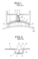
- An example of a conventional shock wave medical treatment apparatus, an ultrasonic wave applicator disclosed in Japanese Patent Application Laid Open No. 62-049843 (1987) is shown in Fig. 1.
- This ultrasonic wave applicator 1 comprises a
concave oscillator 2 of 10 cm diameter and a constant curvature for generating focused ultrasonic waves which has an aperture of a prescribed shape at a middle, a backing material 3 attached to a back of thisconcave oscillator 2 uniformly, an imaging ultrasonic wave probe 4 for taking images of region to be treated by transmitting and receiving imaging ultrasonic waves which is fixed at the aperture of theconcave oscillator 2 and which is a sector scanning type having anarray 4a of minute oscillator elements at a bottom face, and anacoustic coupler 5 for propagating the focused ultrasonic waves from theconcave oscillator 2 to asurface 32S of a patient which is made of abag 6 of thin film having an acoustic impedance substantially equal to that of water and which is filled with water. - In this ultrasonic wave applicator 1, the
array 4a of the oscillator elements of the imaging ultrasonic wave probe 4 is either aligned with a curved ultrasonic wave generating surface of theconcave oscillator 2 or placed further away from thesurface 32S of the patient than the curved ultrasonic wave generating surface of theconcave oscillator 2. - In such a configuration, the imaging ultrasonic waves to be transmitted and received by the imaging ultrasonic wave probe 4 inevitably suffer from scattering and dissipation due to the intervening water inside the
acoustic coupler 5 and the thin film of thebag 6. For this reason, the images to be displayed by a display unit (not shown) are influenced by noise so that locating the object to be treated becomes difficult. - On the other hand, there is an alternative configuration for the ultrasonic wave applicator which is shown in Fig. 2.
- This
ultrasonic wave applicator 7 comprises a concave oscillator 9 for generating ultrasonic waves of focusingtrajectory 12 which is similar to theconcave oscillator 2 of the previous example described above and which is located below abed 8, awater bag 10 filled with water for transmitting the ultrasonic waves which is provided between an ultrasonic wave generating surface of the concave oscillator 9 and anopening 13 of thebed 8 located above the concave oscillator 9, and amechanical probe 11 placed inside thewater bag 10 which has a fixed focal length. - In this alternative configuration, the problem of scattering and dissipation as described above for the previous example is also present. In addition, there are problems due to the fact that the
probe 11 is a mechanical probe, such as deterioration of the image quality, enlargement of the configuration, and vulnerability against vibrations. Moreover, in a configuration of Fig. 2, operation of theultrasonic wave applicator 7 is harder because thisultrasonic wave applicator 7 is fixed to thebed 8. - To deal with such problems of a conventional shock wave medical treatment apparatus, the present inventor has proposed a shock wave applicator comprising a shock wave transducer for generating shock waves with a focal point located inside a patient, a water bag provided at a shock wave generating surface of the shock wave transducer, and an imaging ultrasonic transducer located between the shock wave generating surface and the focal point for taking image data of the patient in a region including the focal point in a state of contacting its ultrasonic wave transmitting and receiving surface to a surface of the patient, as disclosed in Japanese Patent Application Laid Open No. 62-290158 (1987).
- Now, in general, a distance from a body surface to the object to be treated varies according to an organ containing the object to be treated and depending on whether the patient is adult or child. Moreover, the dissipation of the ultrasonic wave varies depending on a physical constitution of the patient.
- For these reasons, there arises a necessity to change the imaging ultrasonic wave probe to that of different characteristic in accordance with the distance of the object to be treated from the body surface and the physical constitution of the patient.
- However, an exchangeability of the imaging ultrasonic wave probe has not been considered in the conventional shock wave medial treatment apparatus, so that the imaging ultrasonic wave probe could not be changed so easily.
- It is therefore an object of the present invention to provide a shock wave medical treatment apparatus in which the imaging ultrasonic wave probe can be changed among those of different imaging region depths, so that locating of the object to be treated inside the patient becomes easier.
- This object is achieved in the present invention by providing a shock wave medical treatment apparatus, equipped with a shock wave applicator comprising: shock wave transducer means for generating shock waves with a focal point inside a body to be treated, having an aperture at a center; imaging ultrasonic wave probe means for taking images of the body to be treated containing the focal point of the shock wave; and housing pipe means, placed on a line joining the focal point of the shock wave and a center of the aperture of the shock wave transducer means, for exchangeably holding the imaging ultrasonic wave probe means.
- Other features and advantages of the present invention will become apparent from the following description taken in conjunction with the accompanying drawings.
- Fig. 1 is a schematic cross sectional view of one example of a conventional shock wave medical treatment apparatus.
- Fig. 2 is a schematic cross sectional view of another example of a conventional shock wave medical treatment apparatus.
- Fig. 3 is a schematic block diagram of one embodiment of a shock wave medical treatment apparatus according to the present invention.
- Fig. 4 is a detailed cross sectional view of a shock wave transducer in the apparatus of Fig. 3.
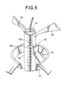
- Fig. 5 is an enlarged cross sectional view of a position detection unit of the shock wave transducer of Fig. 4.
- Fig. 6 is an enlarged cross sectional view of a portion A of the shock wave transducer of Fig. 4.
- Fig. 7 is an enlarged cross sectional view of a portion B of the shock wave transducer of Fig. 4.
- Fig. 8 is an enlarged cross sectional view of a portion C of the shock wave transducer of Fig. 4.
- Fig. 9 is an enlarged cross sectional view of a portion D of the shock wave transducer of Fig. 4.
- Fig. 10 is an enlarged cross sectional view of an alternative configuration for the portion D shown in Fig. 9.
- Fig. 11 is an enlarged cross sectional view of an alternative configuration for the portion C shown in Fig. 8.
- Referring now to Fig. 3, there is shown one embodiment of a shock wave medical treatment apparatus according to the present invention, in a form of an ultrasonic medical treatment apparatus.
- In this embodiment, the shock wave medical treatment apparatus comprises a
shock wave applicator 17 including ashock wave transducer 15 for generating ultrasonic shock waves as shock waves for treatment and an imagingultrasonic wave probe 16 for transmitting and receiving imaging ultrasonic waves, which will be described in greater detail below, apulser 18 for activating theshock wave transducer 15 by supplying pulsed signals, a transmitter andreceiver circuit 19 for activating the imagingultrasonic wave probe 16 into sector scanning by supplying pulsed signals and receiving echo signals obtained by the imagingultrasonic wave probe 16 as a result of the sector scanning, asignal processing circuit 20 for converting output signals of the transmitter and receiver circuit into video signals by detecting amplitudes of the output signals, asignal transformation unit 21 such as a digital scan converter for performing signal transformation operation on output signals of thesignal processing circuit 20, aCPU 22 for controlling elements of the apparatus, apulsed signal controller 23 for controlling timings, amplitudes and frequencies of the pulsed signals at thepulser 18 and the transmitter andreceiver circuit 19, adisplay unit 27 for displaying images such as those of a patient's body surface, an organ of interest, and concretion to be treated in the organ of interest in a fanshape imaging region 25 imaged by the imagingultrasonic wave probe 16 along with afocal point marker 26 indicating a focal point of the ultrasonic shock waves generated by theshock wave transducer 15 and other information, aswitch 29 for activating the supply of the pulsed signals by thepulser 18 to theshock wave transducer 15, and aposition controller 30 for controlling a relative position of theshock wave transducer 15 with respect to the imagingultrasonic wave probe 16. - Referring now to Figs. 4 to 9, a detail configuration of the
shock wave applicator 17 will be described. - As shown in Fig. 4, the
shock wave applicator 17 comprises theshock wave transducer 15 for generating the ultrasonic shock wave for treating an object to be treated such as a concretion in an organ, from its constantly curved shockwave generating surface 15a equipped with concave oscillator, with thefocal point 41a located inside thepatient 32, which has a central aperture A, awater bag 33 as an acoustic coupler which is filled with water for propagating the ultrasonic shock waves from theshock wave transducer 15 to thepatient 32 and which is attached to theshock wave transducer 15 on the shockwave generating surface 15a side, and the imagingultrasonic wave probe 16 having an array of minute oscillator elements at abottom face 16a for taking images in a region to be treated 42 including thefocal point 41a by transmitting and receiving imaging ultrasonic waves with thebottom face 16a contacting thebody surface 32S of thepatient 32, which is located on a line L joining a center of the central aperture A and thefocal point 41a. - In this
shock wave applicator 17, the imagingultrasonic wave probe 16 is housed inside acylindrical housing pipe 54 made of stainless steel which has an inner diameter slightly larger than an outer diameter of the imagingultrasonic wave probe 16, and at the central aperture A of theshock wave transducer 15 a cup shaped connectingmember 43 having a slightly larger inner diameter than an outer diameter of thehousing pipe 54 for supporting theshock wave transducer 15 with respect to thehousing pipe 54 is provided around thehousing pipe 54. - This
shock wave applicator 17 is equipped with a tilting mechanism for theshock wave transducer 15 and the imagingultrasonic wave probe 16 so that theshock wave transducer 15 and the imagingultrasonic wave probe 16 can be tilted to a desired direction toward thepatient 32. The tilting mechanism comprises a couple of symmetrically arrangedconnectors 83, each of which having afirst guide 82 at a top which is slidably engaged to acircular guide rail 81. Thecircular guide rail 81 is suspended by asuspension frame 80 which can suspend the entireshock wave applicator 17, and is curved such that it has a shape of a part of circle centered around a middle of thebottom face 16a of the imagingultrasonic wave probe 16. Eachconnector 83 has two bottom ends one of which is connected to a top end portion of thehousing pipe 54 while another one of which is connected to avertical guide rail 84 provided parallel to thehousing pipe 54 by theshock wave transducer 15. Theshock wave transducer 15 is connected with thevertical rails 84 throughsecond guides 85 attached at an edge of theshock wave transducer 15 which are slidably engaged with thevertical guide rails 84. Each of thevertical guide rails 84 has astopper 84a at a bottom end to prevent thesecond guide 85 from disengaging off thevertical guide rail 84. Thus, by sliding thefirst guides 82 along thecircular guide rail 81 manually, theshock wave transducer 15 and the imagingultrasonic wave probe 16 can be tilted to a desired direction toward thepatient 32, without changing a relative position of theshock wave transducer 15 with respect to the imagingultrasonic wave probe 16. Also, a vertical plane in which the tilting takes place can be rotated by rotating thesuspension frame 80 around. - Furthermore, between the connecting
member 43 and thehousing pipe 54, there is provided adriver unit 36 for moving theshock wave transducer 15 in a direction E with respect to thehousing pipe 54. Thisdriver unit 36 comprises arack 36a fixed on a side face of thehousing pipe 54, apinion gear 36b to be engaged with therack 36a, amotor 36c as a source of driving power whose driving axis is connected to thepinion gear 36b, and a supportingmember 36d for supporting themotor 36c with respect to the connectingmember 43. Thedriver unit 36 moves theshock wave transducer 15 in a desired manner indicated by a control signal supplied from theposition controller 30 appeared in Fig. 3. - A position of the
shock wave transducer 15 in the direction E with respect to thehousing pipe 54 is detected by aposition detection unit 90. As shown in Fig. 5, theposition detection unit 90 comprisesscale markings 90a provided on a side face of thehousing pipe 54 for indicating prescribed intervals, aphoto sensor 90b for reading thescale markings 90a, and a supportingelement 91 for supporting thephoto sensor 90b with respect to the connectingmember 43. - The reading of the scale markings read by the
photo sensor 90b is signaled to theposition controller 30, which in turn controls rotation angle of the driving axis of themotor 36c such that the position of theshock wave transducer 15 with respect to the imagingultrasonic wave probe 16 is controlled in a desired manner. When themotor 36c is not activated, the position of theshock wave transducer 15 is held fixed. - As shown in Fig. 6, in a vicinity of the central aperture A of the
shock wave transducer 15, the connectingmember 43 includes alower pipe section 43b having agroove 43a for housing an O-ring 52 on an inner circumference side in contact with thehousing pipe 54. The connectingmember 43 is also equipped with astopper member 51 having anupper pipe section 51b, anut section 51a extending perpendicular to theupper pipe section 51b, and abolt 53 to be engaged into thenut section 51a for fastening thestopper member 51 to a main part of the connectingmember 43. Thelower pipe section 43b and theupper pipe section 51b function to keep thehousing pipe 54 from tilting with respect to the connectingmember 43, while the O-ring 52 function to prevent leakage of the water contained inside thewater bag 33 even when theshock wave transducer 15 is moved in the direction E. - The
water bag 33 comprises aside face 33a in a form of bellows that can extend or contract in a certain range of angles around the direction E whose upper circumference is attached to the circumference of theshock wave transducer 15, and abottom face 37 made of a thin film of rubber which has substantially equivalent acoustic impedance as the water. - As shown in Fig 7, the
bottom face 37 has anouter reinforcement ring 37a formed around its outer rim, and theside face 33a and thebottom face 37 are connected by pinching an edge of theside face 33a and thereinforcement ring 37a together in between ring shapedfittings - On the other hand, as shown in Fig. 8, the
bottom face 37 also has aninner reinforcement ring 37b formed around its inner rim, and thebottom face 37 are fixed by pinching thereinforcement ring 37a in between ring shapedfittings bolt 73. - In addition, in order to wrap around an end portion of the imaging
ultrasonic wave probe 16 with an innerside wall portion 37c of thebottom face 37 tightly, there is provided anadditional reinforcement member 75 made of rubber harder than that of thebottom face 37, at the innerside wall portion 37c, which is held fixed on the innerside wall portion 37c by aband 74, and an elastic ring shapedsponge 76 attached to the end portion of the imagingultrasonic wave probe 16. - Thus, as being made of thin film, the
bottom face 37 may be ripped off, but in such a case thebottom face 37 can easily be replaced by separating thefittings outer reinforcement ring 37a off, removing the water inside thewater bag 33, separating thefittings band 74 on the innerside wall portion 37c. - Now, the imaging
ultrasonic wave probe 16 has a fixed penetration depth, and this in turn determines a depth of the region to be treated. On the other hand, a distance between the body surface and the concretion differs for an adult patient and a child patient, even when the organ containing the concretion is identical. For this reason, it is preferable to use the imagingultrasonic wave probe 16 of low frequency (3.75 MHz) for an adult patient in order to take image at deeper position, and to use the imagingultrasonic wave probe 16 of high frequency (5 MHz) for a child patient in order to take image at shallower position. The high frequency imagingultrasonic wave probe 16 also has an advantage of being capable to obtain high quality images. Similarly, it is preferable to select an appropriate one from more than one imagingultrasonic wave probe 16 of different frequencies depending on depths of the concretion to be disintegrated. Also, it is preferable to select an appropriate one from more than one imaging ultrasonic wave probes16 of different frequencies depending on physical constitution of the patient, such as the imagingultrasonic wave probe 16 of low frequency for a muscular patient, and the imagingultrasonic wave probe 16 of high frequency for a less muscular patient. - For this reason, in this embodiment, the imaging
ultrasonic wave probe 16 is housed inside thehousing pipe 54 so as to be easily changed by another. Moreover, in this embodiment, the imagingultrasonic wave probe 16 is rotatable around its central axis. More specifically, as shown in Fig. 9, a clearance of about 0.5 to 1 mm is provided between the inner diameter of thehousing pipe 54 and the outer diameter of the imagingultrasonic wave probe 16 so that the imagingultrasonic wave probe 16 can easily be inserted into thehousing pipe 54. In addition, the imagingultrasonic wave probe 16 has agroove 16c in a vicinity of its top end portion such that abolt 16b can be fastened through ahole 54a provided on thehousing pipe 54 into thegroove 16c. When thebolt 16b is fully tightened the imagingultrasonic wave probe 16 can be fixed at a desired position, whereas when thebolt 16 is only loosely tightened the imagingultrasonic wave probe 16 can be rotated around its central axis. - Now, the operation of this embodiment of a shock wave medical treatment apparatus will be described for an exemplary case of treating a
concretion 39 inside anorgan 38 shown in Fig. 4. - The imaging
ultrasonic wave probe 16 having an appropriate penetration depth for thisconcretion 39 to be treated is selected in advance, installed into the thehousing pipe 54, and fixed by means of thebolt 16b. - Then, the
water bag 33 of theshock wave applicator 17 is placed over thebody surface 32S of thepatient 32 above theorgan 38, with the imagingultrasonic wave probe 16 contacting thebody surface 32S. - Next, the imaging
ultrasonic wave probe 16 is activated along with the transmitter andreceiver circuit 19, thesignal processing circuit 20, and thesignal transformation unit 21, such that a tomographic image of thepatient 32 is displayed on thedisplay unit 27. Here, because the imagingultrasonic wave probe 16 is contacting thebody surface 32S, a very clear image without influences of the water or thebottom face 37 of thewater bag 33 is obtainable, and this helps a quick and easy apprehension of theconcretion 39. - Next, the imaging
ultrasonic wave probe 16 is operated to show theconcretion 39 on the tomographic image displayed on thedisplay unit 27. This operation may involve such maneuvering for obtaining a clearer image as tilting the imagingultrasonic wave probe 16 by sliding the first guides 82 along thecircular guiding rail 81, and rotating the imagingultrasonic wave probe 16 around the line L by slightly loosening thebolt 16b. - On the fan
shape imaging region 25 of thedisplay unit 27, a relative position of thefocal point 41a of theshock wave transducer 15 with respect to the imagingultrasonic wave probe 16 is indicated in real time in a form of themarker 26 according to the signals from theposition detection unit 90 transmitted through theCPU 22 and thesignal transformation unit 21. When theconcretion 39 is displayed on the tomographic image, theposition controller 30 is operated to move theshock wave transducer 15 in the direction E until themarker 26 and theconcretion 39 coincide on thedisplay unit 27. Here, because thebottom face 16a of the imagingultrasonic wave probe 16 is located on the line L joining a center of the central aperture A and thefocal point 41a, theconcretion 39 can be displayed at a center of the displayed image, and this also helps a quick and easy apprehension of theconcretion 39. Also, because the relative position of theshock wave transducer 15 with respect to the imagingultrasonic wave probe 16 is adjustable, the treatment operation become easier. - Next, the
switch 29 is operated to send the control signal to thepulser 18 through theCPU 22 and thepulsed signal controller 23, such that the pulsed signals are transmitted from thepulser 18 to theshock wave transducer 15 and the powerful ultrasonic shock waves are generated from theshock wave transducer 15 toward theconcretion 39 located at the position indicated by themarker 26 on thedisplay unit 27 to disintegrate theconcretion 39. Such a shock wave application is repeated as many times as necessary to completely disintegrate theconcretion 39. - As described, in this embodiment of a shock wave medical treatment apparatus, a quick and easy apprehension of the
concretion 39 is possible because a very clear image without influences of the water or thebottom face 37 of thewater bag 33 is obtainable as a result of the fact that the imagingultrasonic wave probe 16 is contacting thebody surface 32S. - A clear image is obtainable also because the imaging
ultrasonic wave probe 16 is rotatable around its central axis,
Moreover, the imagingultrasonic wave probe 16 is housed inside thehousing pipe 54 so that one having an appropriate penetration depth can quickly and easily be installed. - In addition, since the imaging
ultrasonic wave probe 16 is completely separated from the water in thewater bag 33, the damaging of the imaging elements due to wetting of the imaging elements through the lenses covering the imaging elements, which has been accompanying the change of the probe in a conventional shock wave medical treatment apparatus, can be prevented. - Also, because of the
water bag 33 which functions as an acoustic coupler, the shock wave can be transmitted efficiently. - Also, because the side face of the
water bag 33 are bellows, thewater bag 33 can easily be stretched or contracted in a vertical direction, and the adjustment of the relative position of theshock wave transducer 15 with respect to the imagingultrasonic wave probe 16 becomes easier. Here, the leakage of the water from thewater bag 33 in moving theshock wave transducer 15 is prevented by the O-ring 52 provided between the connectingmember 43 and thehousing pipe 54. - Also, because the
focal point 41a of the ultrasonic shock wave from theshock wave transducer 15 is indicated on thedisplay unit 27 by themarker 26, an accurate treatment can be performed easily. - Now, there are several variations of the embodiment described above possible.
- First of all, a configuration of a portion D in Fig. 4, which is shown in detail in Fig. 9, may be altered to that shown in Fig. 10. In this alternative configuration, the imaging
ultrasonic wave probe 162 is equipped with astopper 162a at its top end, which replaces thegroove 16c of the above embodiment. Thus, when the imagingultrasonic wave probe 162 is inserted into thehousing pipe 54, the position of the imagingultrasonic wave probe 162 is determined as thestopper 162a abuts the top edge of thehousing pipe 54. The imagingultrasonic wave probe 162 can be fixed, or made free to rotate by tightening or loosening thebolt 16b as in the above embodiment. - Also, the
shock wave transducer 15 may be of an electromagnetic induction type shock wave generator instead of a generator using oscillator elements as in the above embodiment. - Also, a configuration of a portion C in Fig. 4, which is shown in detail in Fig. 8, may be altered to that shown in Fig. 11. In this alternative configuration, the
bottom face 37 of thewater bag 33 is extended to cover thebottom face 16a of the imagingultrasonic wave probe 16, while at the lower end of thehousing pipe 54, which is shorter than the imagingultrasonic wave probe 16 in this case, there is provide an O-ring 54d for preventing the water from entering into thehousing pipe 54, which is contacting the side face of the imagingultrasonic wave probe 16. In this case, since the water that comes between the imagingultrasonic wave probe 16 and thebody surface 32S possesses an acoustic impedance close to that of a human body, the efficient transmission of the ultrasonic wave is possible. - Also, the
position detection unit 90 of the above embodiment may be replaced by a potentiometer of variable resistor type provided in conjunction with thepinion gear 36b. - Also, instead of moving the
shock wave transducer 15, the imagingultrasonic wave probe 16 may be made to be movable with respect to theshock wave transducer 15. - Besides these, many modifications and variations of the above embodiments may be made without departing from the novel and advantageous features of the present invention. Accordingly, all such modifications and variations are intended to be included within the scope of the appended claims.
Claims (9)
- A shock wave medical treatment apparatus, equipped with a shock wave applicator comprising:
shock wave transducer means (15) for generating shock waves with a focal point (41a) inside a body (32) to be treated, having an aperture at a center;
imaging ultrasonic wave probe means (16) for taking images of the body to be treated containing the focal point (41a) of the shock wave; and
housing pipe means (54), placed on a line joining the focal point (41a) of the shock wave and a center of the aperture of the shock wave transducer means (15), for exchangeably holding the imaging ultrasonic wave probe means (16). - The apparatus of claim 1, further comprising means (36) for changing relative position of the shock wave transducer means (15) and the imaging ultrasonic wave probe means (16).
- The apparatus of claim 1 or 2, further comprising an acoustic coupler means (33), arranged to be in contact with the shock wave transducer means (15), for propagating the shock wave between the shock wave transducer means and the body (32) to be treated.
- The apparatus of claim 3, wherein the acoustic coupler means comprises a water bag (33) filled with water capable of stretching and contracting at least in a direction along the line joining the focal point (41a) of the shock wave and a center of the aperture of the shock wave transducer means (15).
- The apparatus of claim 4, wherein the water in the acoustic coupler means (33) and the imaging ultrasonic wave probe means (16) are completely separated by the housing pipe means (54).
- The apparatus of any of claims 3 to 5, wherein a bottom face (16a) of the imaging ultrasonic wave probe means (16) and a bottom face (37) of the acoustic coupler means (33) can directly contact with a surface (32S) of the body (32) to be treated.
- The apparatus of any of claims 1 to 6, wherein the housing pipe means (54) holds the imaging ultrasonic wave probe means (16) to be rotatable around a central axis of the imaging ultrasonic wave probe means.
- The apparatus of claim 7, wherein the housing pipe means (54) is equipped with means (16b) for preventing the imaging ultrasonic wave probe (16) from rotating.
- The apparatus of any of claims 1 to 8, further comprising display means (27) for displaying images taken by the imaging ultrasonic wave probe means (16) along with a marking (26) indicating a location of the focal point (41a) of the shock wave in the images.
Priority Applications (3)
| Application Number | Priority Date | Filing Date | Title |
|---|---|---|---|
| EP90104278A EP0445322B1 (en) | 1990-03-06 | 1990-03-06 | Shock wave medical treatment apparatus with exchangeable imaging ultrasonic wave probe |
| DE1990625165 DE69025165T2 (en) | 1990-03-06 | 1990-03-06 | Medical device for shock wave treatment with exchangeable ultrasound probe |
| US07/807,617 US5165412A (en) | 1990-03-05 | 1991-12-13 | Shock wave medical treatment apparatus with exchangeable imaging ultrasonic wave probe |
Applications Claiming Priority (1)
| Application Number | Priority Date | Filing Date | Title |
|---|---|---|---|
| EP90104278A EP0445322B1 (en) | 1990-03-06 | 1990-03-06 | Shock wave medical treatment apparatus with exchangeable imaging ultrasonic wave probe |
Publications (2)
| Publication Number | Publication Date |
|---|---|
| EP0445322A1 true EP0445322A1 (en) | 1991-09-11 |
| EP0445322B1 EP0445322B1 (en) | 1996-01-31 |
Family
ID=8203721
Family Applications (1)
| Application Number | Title | Priority Date | Filing Date |
|---|---|---|---|
| EP90104278A Expired - Lifetime EP0445322B1 (en) | 1990-03-05 | 1990-03-06 | Shock wave medical treatment apparatus with exchangeable imaging ultrasonic wave probe |
Country Status (2)
| Country | Link |
|---|---|
| EP (1) | EP0445322B1 (en) |
| DE (1) | DE69025165T2 (en) |
Cited By (2)
| Publication number | Priority date | Publication date | Assignee | Title |
|---|---|---|---|---|
| FR2747559A1 (en) * | 1996-04-18 | 1997-10-24 | Siemens Ag | THERAPY APPARATUS HAVING SIMPLE ADJUSTMENT OF A DESIRED DISTANCE TO A REFERENCE POINT |
| WO2002047560A1 (en) * | 2000-12-15 | 2002-06-20 | Dornier Medtech Holding International Gmbh | Coupling bellows for shockwave therapy |
Families Citing this family (2)
| Publication number | Priority date | Publication date | Assignee | Title |
|---|---|---|---|---|
| DE10007858C1 (en) * | 2000-02-21 | 2001-12-20 | Dornier Medizintechnik | Bag, for coupling focussed shock wave source to body, is made of rubber elastic material with different wall thicknesses allowing size of bag to be varied |
| DE102005037043C5 (en) | 2005-08-05 | 2017-12-14 | Dornier Medtech Systems Gmbh | Shock wave therapy device with image acquisition |
Citations (4)
| Publication number | Priority date | Publication date | Assignee | Title |
|---|---|---|---|---|
| FR2587493A1 (en) * | 1985-07-08 | 1987-03-20 | Ngeh Toong See | Device for location and guidance by ultrasound |
| EP0316863A2 (en) * | 1987-11-16 | 1989-05-24 | Kabushiki Kaisha Toshiba | Shock wave treatment apparatus |
| DE3900893A1 (en) * | 1988-01-13 | 1989-08-03 | Toshiba Kawasaki Kk | SHOCK WAVE TREATMENT DEVICE |
| EP0301360B1 (en) * | 1987-07-31 | 1993-11-18 | Siemens Aktiengesellschaft | Shock wave apparatus with a central ultrasonic location system |
-
1990
- 1990-03-06 DE DE1990625165 patent/DE69025165T2/en not_active Expired - Fee Related
- 1990-03-06 EP EP90104278A patent/EP0445322B1/en not_active Expired - Lifetime
Patent Citations (4)
| Publication number | Priority date | Publication date | Assignee | Title |
|---|---|---|---|---|
| FR2587493A1 (en) * | 1985-07-08 | 1987-03-20 | Ngeh Toong See | Device for location and guidance by ultrasound |
| EP0301360B1 (en) * | 1987-07-31 | 1993-11-18 | Siemens Aktiengesellschaft | Shock wave apparatus with a central ultrasonic location system |
| EP0316863A2 (en) * | 1987-11-16 | 1989-05-24 | Kabushiki Kaisha Toshiba | Shock wave treatment apparatus |
| DE3900893A1 (en) * | 1988-01-13 | 1989-08-03 | Toshiba Kawasaki Kk | SHOCK WAVE TREATMENT DEVICE |
Cited By (3)
| Publication number | Priority date | Publication date | Assignee | Title |
|---|---|---|---|---|
| FR2747559A1 (en) * | 1996-04-18 | 1997-10-24 | Siemens Ag | THERAPY APPARATUS HAVING SIMPLE ADJUSTMENT OF A DESIRED DISTANCE TO A REFERENCE POINT |
| WO2002047560A1 (en) * | 2000-12-15 | 2002-06-20 | Dornier Medtech Holding International Gmbh | Coupling bellows for shockwave therapy |
| US6926680B2 (en) | 2000-12-15 | 2005-08-09 | Dornier Medtech Systems Gmbh | Coupling bellows for shockwave therapy |
Also Published As
| Publication number | Publication date |
|---|---|
| DE69025165D1 (en) | 1996-03-14 |
| EP0445322B1 (en) | 1996-01-31 |
| DE69025165T2 (en) | 1996-10-02 |
Similar Documents
| Publication | Publication Date | Title |
|---|---|---|
| US5165412A (en) | Shock wave medical treatment apparatus with exchangeable imaging ultrasonic wave probe | |
| US4986275A (en) | Ultrasonic therapy apparatus | |
| JP2588938B2 (en) | Shock wave generator for calculus breaking | |
| US5065740A (en) | Ultrasonic medical treatment apparatus | |
| US6190323B1 (en) | Direct contact scanner and related method | |
| US4546771A (en) | Acoustic microscope | |
| US6068599A (en) | Blood vessel puncturing device using ultrasound | |
| US4407294A (en) | Ultrasound tissue probe localization system | |
| US4545385A (en) | Ultrasound examination device for scanning body parts | |
| US5766138A (en) | Therapy apparatus with simple setting of a desired distance from a reference point | |
| US4185502A (en) | Transducer coupling apparatus | |
| EP0316863B1 (en) | Shock wave treatment apparatus | |
| JP2534764B2 (en) | Shock wave therapy device | |
| US4844079A (en) | Lithotripter comprising locating apparatus | |
| US6221014B1 (en) | Device for tracking the focus position for a therapy apparatus | |
| JPH0852151A (en) | Stone crushing device and stone position determining device | |
| EP0445322B1 (en) | Shock wave medical treatment apparatus with exchangeable imaging ultrasonic wave probe | |
| JPH0738857B2 (en) | Calculus crusher | |
| JP2937344B2 (en) | Ultrasound therapy equipment | |
| JPH02114953A (en) | Apparatus for shock wave treatment | |
| JPH07284499A (en) | Ultrasonic therapy applicator | |
| JP2000000244A (en) | Display device for the focal position of the shock wave source | |
| JP2968561B2 (en) | Shock wave therapy device and thermal therapy device | |
| JP2644997B2 (en) | Therapeutic applicator | |
| JP2644237B2 (en) | Ultrasound therapy equipment |
Legal Events
| Date | Code | Title | Description |
|---|---|---|---|
| PUAI | Public reference made under article 153(3) epc to a published international application that has entered the european phase |
Free format text: ORIGINAL CODE: 0009012 |
|
| 17P | Request for examination filed |
Effective date: 19900306 |
|
| AK | Designated contracting states |
Kind code of ref document: A1 Designated state(s): DE FR |
|
| 17Q | First examination report despatched |
Effective date: 19930928 |
|
| GRAA | (expected) grant |
Free format text: ORIGINAL CODE: 0009210 |
|
| AK | Designated contracting states |
Kind code of ref document: B1 Designated state(s): DE FR |
|
| REF | Corresponds to: |
Ref document number: 69025165 Country of ref document: DE Date of ref document: 19960314 |
|
| ET | Fr: translation filed | ||
| PLBE | No opposition filed within time limit |
Free format text: ORIGINAL CODE: 0009261 |
|
| STAA | Information on the status of an ep patent application or granted ep patent |
Free format text: STATUS: NO OPPOSITION FILED WITHIN TIME LIMIT |
|
| 26N | No opposition filed | ||
| PGFP | Annual fee paid to national office [announced via postgrant information from national office to epo] |
Ref country code: DE Payment date: 19991231 Year of fee payment: 11 |
|
| PGFP | Annual fee paid to national office [announced via postgrant information from national office to epo] |
Ref country code: FR Payment date: 20000310 Year of fee payment: 11 |
|
| PG25 | Lapsed in a contracting state [announced via postgrant information from national office to epo] |
Ref country code: FR Free format text: LAPSE BECAUSE OF NON-PAYMENT OF DUE FEES Effective date: 20011130 |
|
| REG | Reference to a national code |
Ref country code: FR Ref legal event code: ST |
|
| PG25 | Lapsed in a contracting state [announced via postgrant information from national office to epo] |
Ref country code: DE Free format text: LAPSE BECAUSE OF NON-PAYMENT OF DUE FEES Effective date: 20020101 |