EP0445622B1 - Procédé d'installation d'un composant à fibre optique et appareil permettant son application - Google Patents
Procédé d'installation d'un composant à fibre optique et appareil permettant son application Download PDFInfo
- Publication number
- EP0445622B1 EP0445622B1 EP91102763A EP91102763A EP0445622B1 EP 0445622 B1 EP0445622 B1 EP 0445622B1 EP 91102763 A EP91102763 A EP 91102763A EP 91102763 A EP91102763 A EP 91102763A EP 0445622 B1 EP0445622 B1 EP 0445622B1
- Authority
- EP
- European Patent Office
- Prior art keywords
- optical fiber
- fiber unit
- pressure
- duct line
- guide tube
- Prior art date
- Legal status (The legal status is an assumption and is not a legal conclusion. Google has not performed a legal analysis and makes no representation as to the accuracy of the status listed.)
- Expired - Lifetime
Links
- 239000013307 optical fiber Substances 0.000 title claims description 89
- 238000000034 method Methods 0.000 title claims description 13
- 239000012530 fluid Substances 0.000 claims description 33
- 238000004891 communication Methods 0.000 claims description 2
- 239000000835 fiber Substances 0.000 claims 1
- 238000003780 insertion Methods 0.000 description 4
- 230000037431 insertion Effects 0.000 description 4
- 238000007796 conventional method Methods 0.000 description 2
- 239000006260 foam Substances 0.000 description 2
- 238000004088 simulation Methods 0.000 description 2
- 239000004698 Polyethylene Substances 0.000 description 1
- 230000000052 comparative effect Effects 0.000 description 1
- 230000003287 optical effect Effects 0.000 description 1
- -1 polyethylene Polymers 0.000 description 1
- 229920000573 polyethylene Polymers 0.000 description 1
- 238000012360 testing method Methods 0.000 description 1
Images


Classifications
-
- G—PHYSICS
- G02—OPTICS
- G02B—OPTICAL ELEMENTS, SYSTEMS OR APPARATUS
- G02B6/00—Light guides; Structural details of arrangements comprising light guides and other optical elements, e.g. couplings
- G02B6/46—Processes or apparatus adapted for installing or repairing optical fibres or optical cables
- G02B6/50—Underground or underwater installation; Installation through tubing, conduits or ducts
- G02B6/52—Underground or underwater installation; Installation through tubing, conduits or ducts using fluid, e.g. air
Definitions
- the present invention relates in general to an apparatus and method for laying optical fiber unit. More specifically, the invention relates to sending an optical fiber unit by pressure.
- Japanese Patent Unexamined Publication No. Sho-59-104607 discloses a conventional method for laying an optical fiber unit into a previously laid duct.
- Fig. 2 (PRIOR ART) illustrates that method.
- An optical fiber unit 23 is fed through an optical fiber unit inlet-side seal portion 26 of a pressure-sending device 21 and from there sent by a driving device 25 toward a duct line 22.
- the duct line 22 is connected with an air tight seal to the pressure-sending device 21.
- Pressure fluid fed from a pressure fluid feed inlet 24 to the pressure-sending device is fed into the duct line 22. It is convenient to use air as the pressure fluid. Accordingly, the optical fiber unit 23 advanced into the duct line 22 is moved by the flow of the pressure fluid.
- the seal portion 26 is provided on the optical fiber unit inlet-side of the pressure-sending device so as to prevent the pressure fluid from flowing backward. This results in the pressure fluid flowing toward the advancing direction of the optical fiber unit only.
- optical fiber unit to be used with the method of the present application is disclosed in the above-mentioned Publication and is an optical fiber unit with a foam layer.
- a foam layer is used as an outer-layer coat, it has the advantageous characteristics of both being light-weight and having an extremely uneven surface. Such an uneven surface provides a wide surface area so that a large force of pressure can be used to advance the optical fiber unit through the duct.
- the method for laying an optical fiber unit under fluid pressure into a previously laid duct line by means of a pressure-sending device having means for feeding the pressure fluid into the duct line and means for sending the optical fiber unit into the duct line is characterized in that the pressure fluid is fed into the pressure-sending device and from there the pressure fluid flows not only to the duct line but to the inlet-side guide tube and the pressure fluid flows in the guide tube in the direction opposite to the advancing direction of the optical fiber unit.
- the optical fiber unit laying apparatus for sending an optical fiber unit under fluid pressure from a feeding reel for storing the optical fiber unit to a previously laid duct line so as to lay the optical fiber unit is defined in claim 2.
- the apparatus comprises: a pressure device providing a fluid under pressure which fluid is fed into the device from a source such as a compressor; a driving device for moving the optical fiber unit from the feeding reel through a guide tube into the pressure device and on into the duct line; the apparatus may further comprise a connector connecting the duct line with the pressure device; and another connector connecting the guide tube with the pressure device.
- Fig. 1 is a sectional view for explaining an embodiment of the present invention
- Fig. 2 (PRIOR ART) is a schematic view of a conventional pressure-sending device
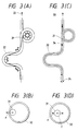
- Fig. 3 is a view for explaining the operation of the present invention compared with the conventional apparatus
- Fig. 4 is a sectional view of the pressure device for explaining another embodiment of the present invention
- Figs. 5 and 6 are views for explaining specific laying methods.
- buoyant force f for holding an optical fiber unit at the center of a duct line 32 is made to act by the fluid 34 flowing in the direction opposite to the advancing direction of the optical fiber unit 31 through the duct line.
- the buoyant force f is suitable, the above force F and the buoyant force f are balanced with each other, so that the frictional force can be made extremely small. As a result, the optical fiber unit can be propelled with only a small traction force.
- Fig. 1 is a sectional view for explaining an embodiment of the present invention.
- a pressure device 1 a duct line 2; an optical fiber unit 3; an inlet for feeding into the pressure-sending device a pressure fluid such as compressed air from a compressor or the like 4; a driving device 5; a seal portion on the optical fiber unit inlet side 6; an optical fiber unit inlet 7; a guide tube on the optical fiber unit feed side 8; a feeding reel 9; and a back-current fluid 10.
- the optical fiber unit 3 is fed through the seal portion 6 on the optical fiber unit inlet side, sent by the driving device 5 toward the duct line 2 which is connected by an air tight seal to the pressure device 1, and the optical fiber unit moves toward the duct line 2 with the help of a forward-moving pressure fluid fed from the pressure fluid feed inlet 4.
- an inlet-side guide tube 8 is provided on the inlet-side path from the feeding reel 9 to the pressure device 1, and the inlet-side guide tube 8 is connected with an air-tight seal to the optical fiber unit inlet 7 of the pressure device 1.
- the seal portion 6 on the optical fiber unit inlet side of the pressure device 1 provides a gap around the optical fiber unit through which a back-current of pressure fluid flows backward from the pressure-sending device to the inlet-side guide tube 8.
- the optical fiber unit 3 is drawn by the driving device 5 from the inlet-side guide tube toward the duct line while, at the same time, the optical fiber unit 3 is floated by the buoyant force generated by the back current.
- a pressure-sending force acts in the direction opposite to the advancing direction of the optical fiber unit 3.
- This force is however within the range, by several g/m, of the advancing force disclosed in the prior art publication cited above, and thus, the pressure-sending force can be sufficiently overcome by the advancing force of the optical fiber unit propelled by the driving device.
- the pressure of the backward flowing air can be as much as 10 kg/m2 and still be within acceptable range of the advancing force.
- the buoyant force for drawing the optical fiber unit 3 to the center of the guide tube 8 acts in the feed-side section, the generated frictional force is small enough not to cause resistance against drawing the optical fiber unit 3 into the duct line 2, even if the feed-side section has some curves.
- the minimum pressure gradient of the backward flowing air needed to achieve a proper buoyancy is 0.4 ⁇ 10 ⁇ 3 kg/cm2/m.
- the guide tube 8 is on the inlet side of the pressure, and the pressure fluid is caused to flow backward into the guide tube and to flow out from the end of the guide tube as the back-current fluid 10, so that the gap between the optical fiber unit and the seal at the seal portion 6 on the optical fiber unit inlet side of the pressure-sending device can be large, because air-tightness is not required.
- the present invention solves the problem (1) of the prior art described above. Further, even if a vertical duct line in a building is used as the guide tube of the optical fiber unit, the resistance due to the frictional force at the curved portions of the duct line is reduced by the buoyant force due to the fluid which flows backward, and the weight of the optical fiber unit alone can therefore be borne by the driving device. Accordingly, the problem (2) is also solved.
- Fig. 4 is a sectional view for explaining another embodiment of the present invention.
- the portions which correspond to the Fig. 1 embodiment are assigned the same reference numbers as Fig. 1 and no further description of those portions will be given.
- a back-current fluid 10 flows backward through an inlet-side guide tube 8 to an end portion thereof which is connected to a box-like body 12 having a flow adjusting valve, so that the flow of the back-current fluid 10 can be adjusted.
- the adjustment can be performed more easily than the pressure adjustment performed at the seal portion on the optical fiber unit inlet side of the pressure device. Accordingly, it is unnecessary to provide the seal portion as in Fig. 1.
- a brake mechanism 13 may be provided on the feeding reel 9 so as to prevent excessive rotation due to inertia of the feeding reel.
- FIG. 5(A) shows a simulation of piping in a building.
- a vertical duct line 51 having a height of 20 m simulates vertical wiring in the building.
- the vertical duct line 51 has four winding-up duct lines 52 each having a diameter of 40 cm which are disposed at intervals of 5 meters as a simulation of switchboards.
- the vertical duct line 51 is a tube of polyethylene having a total length of 25 m and an inner diameter of 6 mm.
- a coiled duct line 53 of 300 m was connected to the vertical duct line 51 at its upper end so as to simulate a coiled duct line following the duct line in a floor system or the like.
- the optical fiber unit a 7-core optical fiber unit having a tight structure and an outer diameter of 2 mm was used, as described and disclosed in Extended Abstracts B-2-163 of the 1988 Autumn National Convention, the Institute of Electronics, Information and Communication Engineers of Japan.
- a conventional pressure-sending device in the form as shown in Fig. 2 was put at a position a (as shown in Fig. 5(A)) in the vicinity of the lowest portion, the optical fiber unit was inserted by use of compressed air with a pressure of 5 kg/cm2.
- the result of sending the optical fiber unit by pressure was that the pressure speed became lower than 10 m/minute at an optical fiber unit insertion distance of 200 m, and the insertion was stopped in the vicinity of the insertion distance of 300 mm.
- a portion of the optical fiber unit 3 emerging from tube 54 at the top end of the vertical pipe path 51 is inserted into the lower portion of the pressure device 21 so as to draw the optical fiber unit 3 by the driving device 25 using rollers. Even if the drawing speed was selected to be 5 m/minute, 2 m/minute, or 1 m/minute, the optical fiber unit could not be drawn up. It was found that the optical fiber unit 3 could not be inserted into the duct line 2 by this method.
- the pressure device 1 shown in Fig. 1 as the embodiment of the present invention was incorporated at the position b , as shown in Fig. 5(A).
- the optical fiber unit 3 was inserted from the position a to the position b in Fig. 5(A) by a conventional method of short length root pressure-sending.
- the tube 54 of the vertical duct line 51 was connected to the pressure-sending device.
- a feeding reel 64 is positioned far from a pressure device 63, so that the optical fiber unit is fed by pressure through a guide tube 62. Accordingly, the optical fiber unit can be laid in the aerial duct line with no external damage. Also shown in Fig. 6 is a compressor 65, a compressed-air feeding pipe 66, and a valve 67 for adjusting the flow of the backward-flowing fluid.
- optical fiber unit feeding reel is housed in a box-like vessel 12 as shown in Fig. 4, the optical fiber unit can be usefully protected from wind, rain, and other external influences.
- the guide tube 62 between the feeding reel and the pressure device may be a permanent duct line which will continue to be used as an optical cable after the duct line 62 has been laid, or may be a guiding duct line for temporarily guiding the optical fiber unit to the correct starting position only at the time when the unit is originally laid.
Landscapes
- Physics & Mathematics (AREA)
- General Physics & Mathematics (AREA)
- Optics & Photonics (AREA)
- Light Guides In General And Applications Therefor (AREA)
- Electric Cable Installation (AREA)
- Forwarding And Storing Of Filamentary Material (AREA)
Claims (6)
- Procédé de pose d'une fibre optique (3) à travers un conduit (2) comprenant les étapes consistant à :
tirer ladite fibre optique (3) au moyen d'un dispositif d'entraînement depuis une bobine débitrice (9) à travers un tube de guidage (8) et à travers un dispositif de pressurisation (1) délivrant un fluide sous pression dans un conduit (2) ;
diriger une partie dudit fluide sous pression provenant dudit dispositif de pressurisation (1) dans ledit conduit (2) dans le sens de la direction d'avancement de ladite fibre optique (3) ; et simultanément,
diriger une partie dudit fluide sous pression provenant dudit dispositif de pressurisation (1) dans ledit tube de guidage (8) dans le sens opposé à la direction d'avancement de ladite fibre optique, de manière à créer un courant de fluide dans la direction d'avancement de la fibre (3) et dans la direction opposée. - Dispositif de pose d'une fibre optique comportant :
une bobine débitrice (9) pour stocker une fibre optique (3),
un dispositif de pressurisation pour délivrer et diriger un fluide sous pression dans un conduit (3) et un tube de guidage (8) ;
un dispositif d'entraînement (5) de fibre optique pour entraîner ladite fibre optique (3) depuis ledit tube de guidage (8) vers ledit conduit (2) ;
ledit tube de guidage (8) étant relié à et communiquant avec le dispositif de pressurisation (1) et s'éloignant dudit dispositif de pressurisation (1) vers la bobine débitrice (9) ; dans lequel le conduit (2) est relié à et communique avec le dispositif de pressurisation (1) et s'éloigne du dispositif de pressurisation (1) dans la direction d'avancement de la fibre optique. - Dispositif de pose de fibre selon la revendication 2, dans lequel ledit tube de guidage (8) communique avec un corps (12) en forme de boîte entourant ladite bobine débitrice (9).
- Dispositif de pose d'une fibre optique selon la revendication 3, dans lequel ledit corps (12) sous forme de boîte est muni d'une soupape réglable (11).
- Dispositif de pose d'une fibre optique selon la revendication 2, dans lequel un connecteur entre ledit tube de guidage (8) et ledit dispositif de pressurisation (1) comporte une partie rétrécie (55) limitant le débit de fluide entre le dispositif de pressurisation (1) et le tube de guidage (8).
- Dispositif de pose d'une fibre optique selon la revendication 2, dans lequel ledit dispositif de pressurisation (1) communique avec un compresseur.
Applications Claiming Priority (2)
| Application Number | Priority Date | Filing Date | Title |
|---|---|---|---|
| JP2048512A JPH03249704A (ja) | 1990-02-28 | 1990-02-28 | 光ファイバユニットの布設方法および装置 |
| JP48512/90 | 1990-02-28 |
Publications (3)
| Publication Number | Publication Date |
|---|---|
| EP0445622A2 EP0445622A2 (fr) | 1991-09-11 |
| EP0445622A3 EP0445622A3 (en) | 1992-06-03 |
| EP0445622B1 true EP0445622B1 (fr) | 1995-02-01 |
Family
ID=12805424
Family Applications (1)
| Application Number | Title | Priority Date | Filing Date |
|---|---|---|---|
| EP91102763A Expired - Lifetime EP0445622B1 (fr) | 1990-02-28 | 1991-02-25 | Procédé d'installation d'un composant à fibre optique et appareil permettant son application |
Country Status (5)
| Country | Link |
|---|---|
| US (1) | US5143353A (fr) |
| EP (1) | EP0445622B1 (fr) |
| JP (1) | JPH03249704A (fr) |
| AU (1) | AU632903B2 (fr) |
| DE (1) | DE69107103T2 (fr) |
Families Citing this family (39)
| Publication number | Priority date | Publication date | Assignee | Title |
|---|---|---|---|---|
| AU629114B1 (en) * | 1991-03-22 | 1992-09-24 | Sumitomo Electric Industries, Ltd. | Method of constructing an optical wiring network |
| US5293678A (en) * | 1992-02-28 | 1994-03-15 | Comm/Scope | Method for upgrading and converting a coaxial cable with a fiber optic cable |
| SE501770C2 (sv) * | 1992-10-20 | 1995-05-08 | Meab Mobile Equipment Ab | Arrangemang för att med hjälp utav en vätska kunna föra in en eller flera kablar i ett för kabelns omslutande avsett rör |
| US5503370A (en) * | 1994-07-08 | 1996-04-02 | Ctes, Inc. | Method and apparatus for the injection of cable into coiled tubing |
| US5599004A (en) * | 1994-07-08 | 1997-02-04 | Coiled Tubing Engineering Services, Inc. | Apparatus for the injection of cable into coiled tubing |
| GB9419079D0 (en) * | 1994-09-22 | 1994-11-09 | Bicc Plc | Method and apparatus for installing an optical fibre element in a tube |
| US5813658A (en) * | 1994-11-23 | 1998-09-29 | Arnco Corporation | Cable feeding apparatus |
| US5897103A (en) * | 1995-07-24 | 1999-04-27 | Koninklijke Ptt Nederland N.V. | Method for installing cables |
| EP0756186A1 (fr) | 1995-07-24 | 1997-01-29 | Koninklijke KPN N.V. | Procédé et dispositif d'installation d'un câble |
| JP2882628B2 (ja) * | 1996-05-27 | 1999-04-12 | 西日本電線株式会社 | 光ファイバ−ユニット挿入治具 |
| NL1003681C2 (nl) * | 1996-07-25 | 1998-01-28 | Nederland Ptt | Inrichting en werkwijze voor het verwijderen van kabels uit buizen. |
| US6134766A (en) * | 1997-03-24 | 2000-10-24 | Sievert; Thomas M. | Method and apparatus for installing cable-like elements inside pipes |
| US6012621A (en) | 1997-09-04 | 2000-01-11 | Condux International, Inc. | Cable conveying apparatus |
| NL1007210C2 (nl) * | 1997-10-06 | 1999-04-08 | Koninkl Kpn Nv | Werkwijze voor het installeren van kabels in buizen en inrichting voor het toepassen van deze werkwijze. |
| ATE211828T1 (de) * | 1997-12-30 | 2002-01-15 | Emtelle Uk Ltd | Installationsverfahren für ein lichttransmissionsorgan in eine röhre |
| US6179269B1 (en) | 1998-08-21 | 2001-01-30 | Camco International, Inc. | Method and apparatus for installing a cable into coiled tubing |
| US6319618B1 (en) | 1999-02-19 | 2001-11-20 | Zapp Usa, Inc. | Fish tape for conduit distribution |
| US6370753B1 (en) | 2000-07-24 | 2002-04-16 | Arnco Corporation | Method and apparatus for wrapping and installing cable |
| US6691734B2 (en) | 2000-10-10 | 2004-02-17 | Sempra Fiber Links | Methods and systems for installing cable and conduit in pipelines |
| US6736156B2 (en) | 2000-10-10 | 2004-05-18 | Sempra Fiber Links | Method and system for installing cable in pressurized pipelines |
| US6691728B2 (en) | 2000-10-10 | 2004-02-17 | Sempra Fiber Links | Methods and systems for installing a pipeline within a pipeline |
| US7100274B2 (en) * | 2001-11-02 | 2006-09-05 | Neptco Incorporated | Apparatus for applying media to a conduit |
| BR0206267A (pt) * | 2001-11-02 | 2005-01-18 | Neptco Inc | Aparelho e métodos para a aplicação de um meio em um conduto |
| US6745791B2 (en) | 2002-04-26 | 2004-06-08 | Sempra Fiber Links | Service tools for pipelines containing conduit or cable |
| FR2872299A1 (fr) * | 2004-06-24 | 2005-12-30 | France Telecom | Entraineur de micro-cable optique d'encombrement reduit |
| WO2006081269A2 (fr) * | 2005-01-25 | 2006-08-03 | Sabeus, Inc. | Systeme et procede ameliores de deploiement d'une fibre optique dans un puits |
| US8573313B2 (en) * | 2006-04-03 | 2013-11-05 | Schlumberger Technology Corporation | Well servicing methods and systems |
| US20080061101A1 (en) * | 2006-09-12 | 2008-03-13 | Baker Hughes Incorporated | Filamentous member injector and method for injecting filamentous members |
| EP1914577A1 (fr) * | 2006-10-17 | 2008-04-23 | British Telecommunications Public Limited Company | Appareil d'installation de fibre optique |
| EP2075608A1 (fr) * | 2007-12-28 | 2009-07-01 | British Telecmmunications public limited campany | Installation de câble utilisant une détection optique |
| EP2075606A1 (fr) * | 2007-12-28 | 2009-07-01 | British Telecmmunications public limited campany | Installation de câble utilisant l'induction |
| GB0817639D0 (en) * | 2008-09-26 | 2008-11-05 | British Telecomm | Cable installation apparatus |
| EP2230545A1 (fr) | 2009-03-19 | 2010-09-22 | BRITISH TELECOMMUNICATIONS public limited company | Détection passive à distance de courant d'air et de câble |
| GB0905590D0 (en) | 2009-03-31 | 2009-05-13 | British Telecomm | Blown cable apparatus |
| EP2369388A1 (fr) | 2010-03-26 | 2011-09-28 | British Telecommunications public limited company | Plateau porte-épissures de fibres optiques |
| US20150047858A1 (en) * | 2013-08-16 | 2015-02-19 | Schlumberger Technology Corporation | Methods And Systems For Deploying Cable Into A Well |
| WO2015094194A1 (fr) * | 2013-12-17 | 2015-06-25 | Halliburton Energy Services, Inc. | Pompage de guides d'ondes optiques dans des conduites |
| US10920521B2 (en) * | 2019-07-12 | 2021-02-16 | Saudi Arabian Oil Company | Self-contained well intervention system and method |
| DE102021103561B3 (de) | 2021-02-16 | 2022-03-24 | Rittal Gmbh & Co. Kg | Anordnung für den Transport eines Drahtes von einem Drahtkonfektionierungsautomaten zu einer Abnahmestelle |
Family Cites Families (9)
| Publication number | Priority date | Publication date | Assignee | Title |
|---|---|---|---|---|
| EP0108590B1 (fr) * | 1982-11-08 | 1986-11-26 | BRITISH TELECOMMUNICATIONS public limited company | Fibres optiques de transmission |
| US4691896C1 (en) * | 1982-11-08 | 2001-05-08 | British Telecomm | Optical fibre transmission line |
| US4948097C1 (en) * | 1982-11-08 | 2001-05-01 | British Telecomm | Method and apparatus for installing transmission lines |
| DE3340972A1 (de) * | 1983-11-11 | 1985-05-23 | Siemens AG, 1000 Berlin und 8000 München | Verfahren zum einbringen eines lichtwellenleiters in eine schutzhuelle |
| EP0264767B1 (fr) * | 1986-10-15 | 1992-07-15 | Rudolf Harmstorf | Procédé et dispositif pour insérer un élément sous forme de corde dans un conduit de câble |
| GB8706803D0 (en) * | 1987-03-23 | 1987-04-29 | British Telecomm | Optical fibre installation |
| NL193126B (nl) * | 1987-04-28 | 1998-07-01 | Nederland Ptt | Werkwijze en inrichting voor het aanbrengen van een kabel in een kabelgeleidingsbuis. |
| JPS6464517A (en) * | 1987-09-02 | 1989-03-10 | Sumitomo Coal Mining | Wiring method through conduit |
| US5011332A (en) * | 1988-11-14 | 1991-04-30 | Siemens Aktiengesellschaft | Apparatus and method for introducing a cable-like element into a pipe and elements suitable therefor |
-
1990
- 1990-02-28 JP JP2048512A patent/JPH03249704A/ja active Pending
-
1991
- 1991-02-22 US US07/658,868 patent/US5143353A/en not_active Expired - Lifetime
- 1991-02-25 DE DE69107103T patent/DE69107103T2/de not_active Expired - Fee Related
- 1991-02-25 EP EP91102763A patent/EP0445622B1/fr not_active Expired - Lifetime
- 1991-02-27 AU AU71958/91A patent/AU632903B2/en not_active Ceased
Also Published As
| Publication number | Publication date |
|---|---|
| AU7195891A (en) | 1991-08-29 |
| EP0445622A2 (fr) | 1991-09-11 |
| JPH03249704A (ja) | 1991-11-07 |
| AU632903B2 (en) | 1993-01-14 |
| US5143353A (en) | 1992-09-01 |
| EP0445622A3 (en) | 1992-06-03 |
| DE69107103T2 (de) | 1995-05-24 |
| DE69107103D1 (de) | 1995-03-16 |
Similar Documents
| Publication | Publication Date | Title |
|---|---|---|
| EP0445622B1 (fr) | Procédé d'installation d'un composant à fibre optique et appareil permettant son application | |
| US5884384A (en) | Method for installing a tube or a bundle of tubes in an existing tubular duct | |
| CA1246842A (fr) | Reseau de transmission a fibres optiques | |
| EP0345043B1 (fr) | Système d'installation pour une ligne de transmission | |
| US4691896A (en) | Optical fibre transmission line | |
| US5645267A (en) | Method and apparatus for installing transmission lines | |
| JPH0222921B2 (fr) | ||
| US5022634A (en) | Optical fibre installation | |
| EP0323028B1 (fr) | Procédé et dispositif d'installation pneumatique d'un corps à fibre optique | |
| EP0520683B1 (fr) | Procédé et dispositif pour l'installation d'une fibre optique dans un conduit | |
| ES2973729T3 (es) | Instalación de cables en una matriz de conductos | |
| JPH01292302A (ja) | 光ファイバの布設方法 | |
| JPH03249705A (ja) | 通信用線材の布設方法および装置 | |
| JPH04161902A (ja) | 光ファイバケーブル及び長尺線材の布設方法 | |
| JPH0370411A (ja) | チューブを用いた管路内通線方法およびこの方法に使用されるチューブ送出装置 | |
| JP2001095122A (ja) | 光ケーブル空気圧送工法 |
Legal Events
| Date | Code | Title | Description |
|---|---|---|---|
| PUAI | Public reference made under article 153(3) epc to a published international application that has entered the european phase |
Free format text: ORIGINAL CODE: 0009012 |
|
| AK | Designated contracting states |
Kind code of ref document: A2 Designated state(s): DE FR GB NL SE |
|
| PUAL | Search report despatched |
Free format text: ORIGINAL CODE: 0009013 |
|
| AK | Designated contracting states |
Kind code of ref document: A3 Designated state(s): DE FR GB NL SE |
|
| 17P | Request for examination filed |
Effective date: 19920813 |
|
| 17Q | First examination report despatched |
Effective date: 19940309 |
|
| GRAA | (expected) grant |
Free format text: ORIGINAL CODE: 0009210 |
|
| AK | Designated contracting states |
Kind code of ref document: B1 Designated state(s): DE FR GB NL SE |
|
| REF | Corresponds to: |
Ref document number: 69107103 Country of ref document: DE Date of ref document: 19950316 |
|
| ET | Fr: translation filed | ||
| PLBE | No opposition filed within time limit |
Free format text: ORIGINAL CODE: 0009261 |
|
| STAA | Information on the status of an ep patent application or granted ep patent |
Free format text: STATUS: NO OPPOSITION FILED WITHIN TIME LIMIT |
|
| 26N | No opposition filed | ||
| REG | Reference to a national code |
Ref country code: GB Ref legal event code: 746 Effective date: 19990928 |
|
| REG | Reference to a national code |
Ref country code: FR Ref legal event code: D6 |
|
| REG | Reference to a national code |
Ref country code: GB Ref legal event code: IF02 |
|
| PGFP | Annual fee paid to national office [announced via postgrant information from national office to epo] |
Ref country code: SE Payment date: 20040204 Year of fee payment: 14 |
|
| PGFP | Annual fee paid to national office [announced via postgrant information from national office to epo] |
Ref country code: NL Payment date: 20040205 Year of fee payment: 14 |
|
| PGFP | Annual fee paid to national office [announced via postgrant information from national office to epo] |
Ref country code: FR Payment date: 20040210 Year of fee payment: 14 |
|
| PGFP | Annual fee paid to national office [announced via postgrant information from national office to epo] |
Ref country code: GB Payment date: 20040225 Year of fee payment: 14 |
|
| PGFP | Annual fee paid to national office [announced via postgrant information from national office to epo] |
Ref country code: DE Payment date: 20040304 Year of fee payment: 14 |
|
| PG25 | Lapsed in a contracting state [announced via postgrant information from national office to epo] |
Ref country code: GB Free format text: LAPSE BECAUSE OF NON-PAYMENT OF DUE FEES Effective date: 20050225 |
|
| PG25 | Lapsed in a contracting state [announced via postgrant information from national office to epo] |
Ref country code: SE Free format text: LAPSE BECAUSE OF NON-PAYMENT OF DUE FEES Effective date: 20050226 |
|
| PG25 | Lapsed in a contracting state [announced via postgrant information from national office to epo] |
Ref country code: NL Free format text: LAPSE BECAUSE OF NON-PAYMENT OF DUE FEES Effective date: 20050901 Ref country code: DE Free format text: LAPSE BECAUSE OF NON-PAYMENT OF DUE FEES Effective date: 20050901 |
|
| EUG | Se: european patent has lapsed | ||
| GBPC | Gb: european patent ceased through non-payment of renewal fee |
Effective date: 20050225 |
|
| PG25 | Lapsed in a contracting state [announced via postgrant information from national office to epo] |
Ref country code: FR Free format text: LAPSE BECAUSE OF NON-PAYMENT OF DUE FEES Effective date: 20051031 |
|
| NLV4 | Nl: lapsed or anulled due to non-payment of the annual fee |
Effective date: 20050901 |
|
| REG | Reference to a national code |
Ref country code: FR Ref legal event code: ST Effective date: 20051031 |