EP0446193A1 - Procédé et dispositif pour la fusion de matières premières - Google Patents
Procédé et dispositif pour la fusion de matières premières Download PDFInfo
- Publication number
- EP0446193A1 EP0446193A1 EP91850051A EP91850051A EP0446193A1 EP 0446193 A1 EP0446193 A1 EP 0446193A1 EP 91850051 A EP91850051 A EP 91850051A EP 91850051 A EP91850051 A EP 91850051A EP 0446193 A1 EP0446193 A1 EP 0446193A1
- Authority
- EP
- European Patent Office
- Prior art keywords
- pot
- furnace
- heaters
- chamber
- glass
- Prior art date
- Legal status (The legal status is an assumption and is not a legal conclusion. Google has not performed a legal analysis and makes no representation as to the accuracy of the status listed.)
- Granted
Links
- 238000000034 method Methods 0.000 title claims abstract description 25
- 238000002844 melting Methods 0.000 title claims description 11
- 230000008018 melting Effects 0.000 title claims description 11
- 239000000463 material Substances 0.000 title claims description 5
- 239000011521 glass Substances 0.000 claims abstract description 65
- 239000002184 metal Substances 0.000 claims abstract description 34
- 238000010438 heat treatment Methods 0.000 claims abstract description 18
- 238000004519 manufacturing process Methods 0.000 claims abstract description 5
- 238000010309 melting process Methods 0.000 claims abstract description 5
- 238000007599 discharging Methods 0.000 claims description 8
- 239000003795 chemical substances by application Substances 0.000 claims description 7
- 230000005855 radiation Effects 0.000 claims description 7
- 238000007670 refining Methods 0.000 claims description 7
- 239000004575 stone Substances 0.000 claims description 6
- 238000001816 cooling Methods 0.000 claims description 4
- 238000003491 array Methods 0.000 claims description 3
- 238000009833 condensation Methods 0.000 claims 1
- 230000005494 condensation Effects 0.000 claims 1
- 230000001419 dependent effect Effects 0.000 claims 1
- 230000007547 defect Effects 0.000 abstract description 6
- 230000005611 electricity Effects 0.000 abstract 1
- 239000007789 gas Substances 0.000 description 18
- 239000000155 melt Substances 0.000 description 10
- 238000002156 mixing Methods 0.000 description 3
- 238000007664 blowing Methods 0.000 description 2
- 239000011449 brick Substances 0.000 description 2
- 230000001351 cycling effect Effects 0.000 description 2
- 230000003247 decreasing effect Effects 0.000 description 2
- 230000000694 effects Effects 0.000 description 2
- 239000000835 fiber Substances 0.000 description 2
- 229910000953 kanthal Inorganic materials 0.000 description 2
- 230000000284 resting effect Effects 0.000 description 2
- 238000007789 sealing Methods 0.000 description 2
- 238000003756 stirring Methods 0.000 description 2
- 238000009825 accumulation Methods 0.000 description 1
- 239000012467 final product Substances 0.000 description 1
- 238000007511 glassblowing Methods 0.000 description 1
- 239000004615 ingredient Substances 0.000 description 1
- 239000005355 lead glass Substances 0.000 description 1
- 239000000047 product Substances 0.000 description 1
Images


Classifications
-
- C—CHEMISTRY; METALLURGY
- C03—GLASS; MINERAL OR SLAG WOOL
- C03B—MANUFACTURE, SHAPING, OR SUPPLEMENTARY PROCESSES
- C03B5/00—Melting in furnaces; Furnaces so far as specially adapted for glass manufacture
- C03B5/06—Melting in furnaces; Furnaces so far as specially adapted for glass manufacture in pot furnaces
- C03B5/08—Glass-melting pots
-
- Y—GENERAL TAGGING OF NEW TECHNOLOGICAL DEVELOPMENTS; GENERAL TAGGING OF CROSS-SECTIONAL TECHNOLOGIES SPANNING OVER SEVERAL SECTIONS OF THE IPC; TECHNICAL SUBJECTS COVERED BY FORMER USPC CROSS-REFERENCE ART COLLECTIONS [XRACs] AND DIGESTS
- Y02—TECHNOLOGIES OR APPLICATIONS FOR MITIGATION OR ADAPTATION AGAINST CLIMATE CHANGE
- Y02P—CLIMATE CHANGE MITIGATION TECHNOLOGIES IN THE PRODUCTION OR PROCESSING OF GOODS
- Y02P40/00—Technologies relating to the processing of minerals
- Y02P40/50—Glass production, e.g. reusing waste heat during processing or shaping
- Y02P40/57—Improving the yield, e-g- reduction of reject rates
Definitions
- the present invention relates to a method for melting batch materials at the glassworks. More particularly the invention relates to a method of creating a new different temperature profile in a pot furnace for glass metal production, which eliminates several glass defect causes, as well as to a pot furnace in accordance with this new method.
- Glass metal for manual processing by glass-blowing is produced in a furnace by melting batch materials in a pot or a tank at a temperature of about 1400°C.
- the batch contains the basic ingredients for the glass metal.
- This turbulence is intended for creating a stirring effect in the melt which then improves the possibility to achieve a high quality glass metal containing no defects.
- Furnaces for this purpose are disclosed in a number of published patents, for example in CH-173 332, GB-1 121 778, US-941 148, US-2 761 890, US-3 742 111, US-4 143 232 and DE-1 796 039, respectively.
- the Swiss disclosure CH-173 332 is related to strong heating of the upper part of the batch which has proven to be an incorrect method as the refining agent at the top of the batch disappears directly into the air and will therefore to a large extent be consumed before the batch is melted into a glass metal.
- This disclosure further indicates that electric heaters will be placed simply above and below a pot, respectively. Besides, according to what was pointed out previously, viz. that the heater above the pot will have an unfavorable effect on the melting, this arrangement also results in glass vapour very easily forming a layer of glass covering the heater dripping back into the pot if this is of the open type and thereby introducing cords.
- Heating from below is better but the arrangement according to this invention may be dangerous as the method suffers from the constraint that the position of the electric heater easily permits glass metal in the pot to obtain an electric potential through creeping currents. Additionally, it is inevitable that hearth glass spill will enter into the space underneath the pot resulting in a short-circuiting of the heaters after some time due to the accumulation of hearth glass spill.
- the trick for producing high quality glass metal is to create a proper temperature profile in the furnace to ensure a correct melting procedure for the batch and thereby to utilize the refining agent optimally.
- the proper temperature profile will then minimize the stirring or rotation of the fully melted glass metal in the pot to a low desired amount which will as a result reduce or avoid creation of cords and seeds, and consequently result in a production of very high quality glass and at the same time achieving a very high efficiency in the process of utilizing the gases produced by the batch.
- the present invention is disclosing a method to melt the batch in the process of glass metal production for manual glass processing, which in a pot furnace creates a temperature profile forming a melting process resulting in a melted glass metal, which contains very high quality glass metal from the top to the bottom of the pot.
- a pot furnace using electric or gas/oil heating, which is adopting the new temperature profile to obtain very high quality glass metal all the way to the bottom of the pot and which does not require mixing of the batch with cullets and in which the residue will amount to 2 % or less.
- the temperature is redistributed within the furnace and accordingly around the pot in such a way that the melting of the batch proceeds in the pot essentially from below and from the sides, whereby the refining agent will be optimally utilized especially in the lower part of the melt, and the gas forming seeds will early escape from this part as the melting process essentially proceeds from the bottom and the lower parts of the side walls of the pot and upwards.
- the gas achieved from the refining agent can more easily escape since it only has to move through a limited part of the melt and will then efficiently be vented through the still unmelted batch contrary to the commonly used procedure where the batch essentially melts from above and the produced gas in the form of seeds will have a progressively longer path for escaping from the melted glass metal resulting in the fact that a considerable part of such a melt will not produce an acceptable glass quality.
- the new temperature profile is achieved partly by a matching design of the furnace chamber and with electric heaters arranged vertically aligned, i. e. in a circle around the pot without touching the pot or the sidewalls or bottom wall of the furnace chamber.
- the pot is for example placed on top of a number of supports having such a height over the bottom wall that direct radiation from the vertically aligned electric heaters extend below the bottom surface of the pot, and the radiation from those will principally access most of the bottom surface of the pot.
- the other part of this design uses cooling air for the terminal inlets of the electrical heaters and is adapted to be blown along the heaters, thereby reducing radiation and blowing convection air (heat) downwards in the furnace and depending on the somewhat stronger cooling of the upper portions of the heaters, additionally slightly lowering the electric resistance in that portion, will result in a slightly lower power and consequently lower temperature in the upper part of the furnace chamber.
- the lower portions of the electric heaters will have a slightly higher electric resistance and a corresponding higher temperature at a constant voltage over the electric heaters.
- the electric heaters are electrically controlled in a conventional fashion.
- the new temperature profile is achieved partly by a matching design of the furnace chamber along with the main design for the electric furnace and partly by arranging a first lower burner at one end of a first heating channel discharging into a space under the pot, and at least one secondary upper burner in at least one secondary channel discharging into the upper and middle portions of the furnace chamber maintaining the temperature profile in the chamber at a properly balanced furnace pressure to permit easy gathering of glass metal through the gathering opening with low heat outlet.
- the first heating channel is sloping slightly downwards to prevent hearth glass spill from reaching the burner in case of large amounts of hearth glass spill entering the furnace chamber. If hearth glass spill should reach the burner there is a great risk that it would be damaged and the operation of the furnace would be jeopardized.
- the burners are controlled, i. e. electrically, in a conventional fashion.
- the supports on which the pot is placed are arranged in such a manner that the pot will lean about 5 cm towards the furnace door containing the gathering opening. Firstly, this implies that radiation/convection heat towards the front side of the pot will be increased, and secondly that the pot will be prevented from migrating backwards into the furnace chamber which otherwise sometimes is the case for pots with a mouth. At the same time, providing a larger distance between the pot and the door results in a higher temperature at the front side of the pot, the pot must still be readily accessible for a glass-blower's pipe to facilitate gathering of glass metal also deep down into the pot.
- the pot In order to more easily create such a well defined distance the pot is provided with a mouth or an elevated inclined edge projecting towards the gathering opening.
- This mouth of the pot prevents the batch and gathered glass from escaping between the pot and the inner side of the door and thereby after some time destroying it. Besides, at the same time it prevents glass from flowing back to the melt and introducing cords in the melt.
- the lower edge of the gathering opening is lowered to a level below the lower surface of the mouth of the pot whereby a matched stone, for instance suitable brick, is placed for a properly matched interference between the mouth of the pot and the lower portion of the gathering opening.
- a suitable measure of the stone and a fibre mold to achieve adequate sealing between the pot and the gathering opening resulting in minimizing the largest source of heat loss in such a pot furnace.
- the distance between the vertically aligned electric heaters is decreased at the front side of the furnace chamber.
- the secondary burner/burners is/are positioned to deliver more energy at the front side of the furnace chamber.
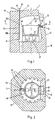
- a pot furnace according to the present invention comprises a furnace body 10 with a furnace door 11 incorporating a gathering opening 12.
- the furnace body defines a chamber by an inner wall 20, an upper floor surface 21 and a ceiling 22.
- the chamber is heated by a number of electric heaters 30 or gas or oil burners 32, 33 to a temperature in the order of 1400°C.
- a pot 40 which is filled with batch materials to be melted into a glass metal.
- the pot 40 can be either of a semi-open or an open type.
- the upper floor surface 21 in the pot furnace contains in a first embodiment four supports 25 onto which the bottom surface 41 of the pot 40 is resting. These supports 25 are designed in a manner that the upper end surfaces of the supports forming a slightly inclined plane towards the furnace opening 12. The pot is thereby given a slight inclination forward of about 5 cm measured horizontally between the vertical planes of the bottom and top edge.
- electric heaters 30 are arranged hanging vertically down from the ceiling 22 of the furnace chamber along a circle of a diameter substantially larger than the outer diameter of the pot 40 and thus encircling the pot 40, as shown in Fig. 2, which is a cross section along the line II - II of Fig. 1.
- Fig. 2 is a cross section along the line II - II of Fig. 1.
- the number of heaters 30 may be different and distributed at different distances to each other to compensate a larger heat loss close to the furnace door 11 containing the gathering opening 12.
- the heaters 30, i.e. the KANTHAL SUPER manufactured by Kanthal AB at Hallstahammar, Sweden, are vertically arranged such that their lower portions 31 are positioned at a predetermined distance above the upper floor surface 21 and in the same manner there is a predetermined distance between the heaters 30 and the side walls 20 of the furnace chamber. Additionally, the heaters 30 are arranged such that the lower portions 31 are positioned well below the bottom surface 41 of the pot 40 such that the bottom surface 41, except for the contact surfaces on top of the supports, will be fully exposed to direct heat radiation from the heaters 30.
- Each heater 30 has a power inlet 34 or an electric terminal at a roof surface 23 with an arrangement to force air into the inlets 34 preventing glass from condensating between the terminals at the inlets 34 causing electric arcing, which destroys the power terminals as well as the hole in the brick-built roof of the furnace carrying the heaters.
- this air is utilized blowing along the heaters such that each upper portion 30a of the heater will be cooled, whereby the heater due to a different temperature of the upper and lower portions will also be presenting slightly different electric resistances in these portions, and at a constant voltage across the heaters 30 those will produce a slightly higher power in the lower portions 30b compared to the upper portions 30a, which then are showing different electric resistances. In this way a temperature gradient is achieved along the heaters 30 and consequently a changed temperature profile is created inside the furnace chamber containing the pot 40.
- a chamber 35 underneath the pot 40 there is formed a chamber 35 underneath the pot 40.
- an opening 26 having a diameter less than the outer diameter of the pot 40. Consequently the pot will primarily be carried by an edge surface around its bottom surface 41.
- first channel 36 which discharges into a chamber 35 underneath the pot for heating of the pot 40.
- This channel is arranged inclined downwards and directed towards the chamber 35 and is, at the other end, provided with a first gas or oil burner, positioned at a level corresponding to the level of the floor surface 21 (or higher up) to prevent glass metal from flooding the burner if the pot should crack.
- at least one secondary channel 37 supplying heat from at least one secondary burner 33 to the rest of the furnace chamber.
- the channel 36 seen from above is tangentially feeding the chamber 35, while in a third embodiment this channel for heating is radially feeding the chamber 35.
- a third embodiment is demonstrated in which the channel 36 forms part of a loop underneath the pot 40, which then will experience an additional support under the bottom surface 41, further decreasing the strain on the bottom surface of the pot, but with some loss of efficiency in the general heating of the bottom surface.
- a corresponding arrangement is demonstrated but in this case the middle of the bottom surface is supported by a couple of supports 61 to obtain more space for the hot gases from the burner 32 to reach most of the bottom surface 41 of the pot 40.
- a fourth embodiment is demonstrated having the pot resting on a number of supports 62 similar to the supports 25 of the first embodiment in Fig 1.
- Channels 36 and 37 respectively with gas or oil burners 32 and 33, respectively, deliver heat to the furnace chamber in a predetermined manner to maintain the preferred temperature profile in the furnace chamber with an initially higher temperature in the lower portions of the furnace.
- the pot is in the preferred embodiment provided with an elevated edge or a mouth 45.
- the lower inner surface of this edge or mouth 45 is inclined outwards and downwards.
- the furnace door 11 containing the gathering opening 12 is arranged such that an edge surface 13 of the gathering opening 12 is levelled below the lower edge surface of the mouth 45, and a suitable stone or brick is fitted on the edge surface 13 together with a fibre mold to achieve a sealing between the upper front of the pot and the gathering opening 12.
- the pot furnace according to a preferred embodiment is additionally provided with a vertically arranged channel 50 exiting into a pocket for hearth glass.
- This exit channel consists of a first portion 51 starting out in the chamber 35 underneath the pot and a second portion 52 having a larger cross section discharging into the pocket for hearth glass spill while the hot exhaust emissions from the furnace are carried out separately through one or several exhaust channels, to for example a chimney.
Landscapes
- Chemical & Material Sciences (AREA)
- Engineering & Computer Science (AREA)
- Materials Engineering (AREA)
- Organic Chemistry (AREA)
- Vertical, Hearth, Or Arc Furnaces (AREA)
- Glass Melting And Manufacturing (AREA)
- Manufacture, Treatment Of Glass Fibers (AREA)
Applications Claiming Priority (6)
| Application Number | Priority Date | Filing Date | Title |
|---|---|---|---|
| SE9000766A SE9000766D0 (sv) | 1990-03-05 | 1990-03-05 | System foer maetning av temperaturfoerdelningen i en degel under smaeltningen av glas |
| SE9000766 | 1990-03-05 | ||
| SE9001730 | 1990-05-14 | ||
| SE9001730A SE465427B (sv) | 1990-03-05 | 1990-05-14 | Foerfarande och degelugn foer smaeltning av glasmaeng |
| SE9001847 | 1990-05-22 | ||
| SE9001847A SE466603B (sv) | 1990-03-05 | 1990-05-22 | Degelugn foer glassmaeltning |
Publications (2)
| Publication Number | Publication Date |
|---|---|
| EP0446193A1 true EP0446193A1 (fr) | 1991-09-11 |
| EP0446193B1 EP0446193B1 (fr) | 1995-11-15 |
Family
ID=27355557
Family Applications (1)
| Application Number | Title | Priority Date | Filing Date |
|---|---|---|---|
| EP91850051A Revoked EP0446193B1 (fr) | 1990-03-05 | 1991-03-04 | Procédé et dispositif pour la fusion de matières premières |
Country Status (3)
| Country | Link |
|---|---|
| EP (1) | EP0446193B1 (fr) |
| DE (1) | DE69114549T2 (fr) |
| ES (1) | ES2083557T3 (fr) |
Cited By (2)
| Publication number | Priority date | Publication date | Assignee | Title |
|---|---|---|---|---|
| IT202200017172A1 (it) * | 2022-08-11 | 2024-02-11 | Claudio Berti | Forno a crogiolo per la fusione e la lavorazione artigianale del vetro, con riscaldamento a tecnologia ibrida ad elevata efficienza energetica |
| US20250027715A1 (en) * | 2022-10-27 | 2025-01-23 | Moris Moshe PEREZ | Furnace |
Families Citing this family (1)
| Publication number | Priority date | Publication date | Assignee | Title |
|---|---|---|---|---|
| CN106746502B (zh) * | 2016-12-26 | 2019-07-23 | 东华大学 | 一种超高温耐侵蚀玻璃电熔炉内衬结构 |
Citations (6)
| Publication number | Priority date | Publication date | Assignee | Title |
|---|---|---|---|---|
| FR390321A (fr) * | 1908-03-24 | 1908-10-02 | Arthur William Onslow | Fabrication du verre |
| US1471824A (en) * | 1922-03-27 | 1923-10-23 | Corning Glass Works | Glass-melting pot |
| US1529480A (en) * | 1923-01-20 | 1925-03-10 | Frederick Charles Hoar | Glass furnace |
| US2541310A (en) * | 1949-07-20 | 1951-02-13 | Uhrmann Franz | Melting kettle for glass |
| FR1103992A (fr) * | 1954-07-12 | 1955-11-15 | Procédé et dispositifs pour la fabrication de creusets notamment pour verreries et cristalleries | |
| FR1448172A (fr) * | 1965-06-21 | 1966-01-28 | Cristallerie Daum Et Cie | Four de fusion à pots sans arcade pour les industries du cristal ou similaire |
-
1991
- 1991-03-04 EP EP91850051A patent/EP0446193B1/fr not_active Revoked
- 1991-03-04 DE DE69114549T patent/DE69114549T2/de not_active Expired - Fee Related
- 1991-03-04 ES ES91850051T patent/ES2083557T3/es not_active Expired - Lifetime
Patent Citations (6)
| Publication number | Priority date | Publication date | Assignee | Title |
|---|---|---|---|---|
| FR390321A (fr) * | 1908-03-24 | 1908-10-02 | Arthur William Onslow | Fabrication du verre |
| US1471824A (en) * | 1922-03-27 | 1923-10-23 | Corning Glass Works | Glass-melting pot |
| US1529480A (en) * | 1923-01-20 | 1925-03-10 | Frederick Charles Hoar | Glass furnace |
| US2541310A (en) * | 1949-07-20 | 1951-02-13 | Uhrmann Franz | Melting kettle for glass |
| FR1103992A (fr) * | 1954-07-12 | 1955-11-15 | Procédé et dispositifs pour la fabrication de creusets notamment pour verreries et cristalleries | |
| FR1448172A (fr) * | 1965-06-21 | 1966-01-28 | Cristallerie Daum Et Cie | Four de fusion à pots sans arcade pour les industries du cristal ou similaire |
Cited By (2)
| Publication number | Priority date | Publication date | Assignee | Title |
|---|---|---|---|---|
| IT202200017172A1 (it) * | 2022-08-11 | 2024-02-11 | Claudio Berti | Forno a crogiolo per la fusione e la lavorazione artigianale del vetro, con riscaldamento a tecnologia ibrida ad elevata efficienza energetica |
| US20250027715A1 (en) * | 2022-10-27 | 2025-01-23 | Moris Moshe PEREZ | Furnace |
Also Published As
| Publication number | Publication date |
|---|---|
| ES2083557T3 (es) | 1996-04-16 |
| EP0446193B1 (fr) | 1995-11-15 |
| DE69114549T2 (de) | 1996-08-08 |
| DE69114549D1 (de) | 1995-12-21 |
Similar Documents
| Publication | Publication Date | Title |
|---|---|---|
| US3742111A (en) | Method and furnace for the electric melting of glass | |
| US5961686A (en) | Side-discharge melter for use in the manufacture of fiberglass | |
| US4029489A (en) | Method of and apparatus for melting of glass | |
| JP2005022969A (ja) | 無機物を溶融する方法および装置 | |
| US4809294A (en) | Electrical melting technique for glass | |
| JPS61132565A (ja) | ガラス溶融タンクおよびそれに用いる耐火物並びにその製造法 | |
| US3524206A (en) | Method and apparatus for melting thermoplastic materials | |
| US2215982A (en) | Electric furnace | |
| US4655812A (en) | Electric heating of glass forehearth | |
| US3942968A (en) | Method and apparatus for melting and subsequently refining glass | |
| US3523781A (en) | Method and apparatus for heating glass melting forehearths | |
| US4026689A (en) | Apparatus for making glass fibers | |
| EP0446193A1 (fr) | Procédé et dispositif pour la fusion de matières premières | |
| US4161617A (en) | Method and apparatus for electrically melting glass | |
| JP4741217B2 (ja) | ガラス溶融体精錬装置 | |
| US3489547A (en) | Apparatus for refining glass | |
| JPH02192421A (ja) | ガラス溶融炉の操作方法及び該方法に使用される炉 | |
| US4705260A (en) | Furnace for heating and melting zinc | |
| US3997316A (en) | Use of crossed electrode pairs in a glassmaking furnace | |
| JPS63185831A (ja) | 電気溶解装置 | |
| US6014402A (en) | Electric resistance melting furnace | |
| US3134828A (en) | Method for heating glass melting pot | |
| US4638490A (en) | Melting furnaces | |
| JP2922482B2 (ja) | 色着せガラス流を供給する方法および装置 | |
| US3941577A (en) | Method and apparatus for making molten glass |
Legal Events
| Date | Code | Title | Description |
|---|---|---|---|
| PUAI | Public reference made under article 153(3) epc to a published international application that has entered the european phase |
Free format text: ORIGINAL CODE: 0009012 |
|
| AK | Designated contracting states |
Kind code of ref document: A1 Designated state(s): DE ES FR GB IT |
|
| 17P | Request for examination filed |
Effective date: 19920225 |
|
| 17Q | First examination report despatched |
Effective date: 19931109 |
|
| GRAA | (expected) grant |
Free format text: ORIGINAL CODE: 0009210 |
|
| AK | Designated contracting states |
Kind code of ref document: B1 Designated state(s): DE ES FR GB IT |
|
| REF | Corresponds to: |
Ref document number: 69114549 Country of ref document: DE Date of ref document: 19951221 |
|
| ITF | It: translation for a ep patent filed | ||
| ET | Fr: translation filed | ||
| REG | Reference to a national code |
Ref country code: ES Ref legal event code: FG2A Ref document number: 2083557 Country of ref document: ES Kind code of ref document: T3 |
|
| PLBQ | Unpublished change to opponent data |
Free format text: ORIGINAL CODE: EPIDOS OPPO |
|
| PLBI | Opposition filed |
Free format text: ORIGINAL CODE: 0009260 |
|
| PLBF | Reply of patent proprietor to notice(s) of opposition |
Free format text: ORIGINAL CODE: EPIDOS OBSO |
|
| 26 | Opposition filed |
Opponent name: AB RAMCO Effective date: 19960815 |
|
| PLBF | Reply of patent proprietor to notice(s) of opposition |
Free format text: ORIGINAL CODE: EPIDOS OBSO |
|
| PGFP | Annual fee paid to national office [announced via postgrant information from national office to epo] |
Ref country code: ES Payment date: 19970416 Year of fee payment: 7 |
|
| PGFP | Annual fee paid to national office [announced via postgrant information from national office to epo] |
Ref country code: FR Payment date: 19970926 Year of fee payment: 7 |
|
| PGFP | Annual fee paid to national office [announced via postgrant information from national office to epo] |
Ref country code: DE Payment date: 19971001 Year of fee payment: 7 |
|
| PG25 | Lapsed in a contracting state [announced via postgrant information from national office to epo] |
Ref country code: ES Free format text: LAPSE BECAUSE OF NON-PAYMENT OF DUE FEES Effective date: 19980305 |
|
| PG25 | Lapsed in a contracting state [announced via postgrant information from national office to epo] |
Ref country code: DE Free format text: LAPSE BECAUSE OF NON-PAYMENT OF DUE FEES Effective date: 19981201 |
|
| REG | Reference to a national code |
Ref country code: FR Ref legal event code: ST |
|
| RDAH | Patent revoked |
Free format text: ORIGINAL CODE: EPIDOS REVO |
|
| PGFP | Annual fee paid to national office [announced via postgrant information from national office to epo] |
Ref country code: GB Payment date: 19990401 Year of fee payment: 9 |
|
| RDAG | Patent revoked |
Free format text: ORIGINAL CODE: 0009271 |
|
| STAA | Information on the status of an ep patent application or granted ep patent |
Free format text: STATUS: PATENT REVOKED |
|
| 27W | Patent revoked |
Effective date: 19990227 |
|
| GBPR | Gb: patent revoked under art. 102 of the ep convention designating the uk as contracting state |
Free format text: 990227 |
|
| PG25 | Lapsed in a contracting state [announced via postgrant information from national office to epo] |
Ref country code: FR Free format text: LAPSE BECAUSE OF NON-PAYMENT OF DUE FEES Effective date: 19980331 |