EP0448225A2 - Input information processing apparatus using pointing means - Google Patents
Input information processing apparatus using pointing means Download PDFInfo
- Publication number
- EP0448225A2 EP0448225A2 EP91301315A EP91301315A EP0448225A2 EP 0448225 A2 EP0448225 A2 EP 0448225A2 EP 91301315 A EP91301315 A EP 91301315A EP 91301315 A EP91301315 A EP 91301315A EP 0448225 A2 EP0448225 A2 EP 0448225A2
- Authority
- EP
- European Patent Office
- Prior art keywords
- input
- processing apparatus
- information processing
- pen
- input information
- Prior art date
- Legal status (The legal status is an assumption and is not a legal conclusion. Google has not performed a legal analysis and makes no representation as to the accuracy of the status listed.)
- Granted
Links
Images


Classifications
-
- G—PHYSICS
- G06—COMPUTING OR CALCULATING; COUNTING
- G06F—ELECTRIC DIGITAL DATA PROCESSING
- G06F3/00—Input arrangements for transferring data to be processed into a form capable of being handled by the computer; Output arrangements for transferring data from processing unit to output unit, e.g. interface arrangements
- G06F3/01—Input arrangements or combined input and output arrangements for interaction between user and computer
- G06F3/03—Arrangements for converting the position or the displacement of a member into a coded form
- G06F3/041—Digitisers, e.g. for touch screens or touch pads, characterised by the transducing means
- G06F3/0416—Control or interface arrangements specially adapted for digitisers
- G06F3/0418—Control or interface arrangements specially adapted for digitisers for error correction or compensation, e.g. based on parallax, calibration or alignment
-
- G—PHYSICS
- G06—COMPUTING OR CALCULATING; COUNTING
- G06F—ELECTRIC DIGITAL DATA PROCESSING
- G06F15/00—Digital computers in general; Data processing equipment in general
- G06F15/02—Digital computers in general; Data processing equipment in general manually operated with input through keyboard and computation using a built-in program, e.g. pocket calculators
-
- G—PHYSICS
- G06—COMPUTING OR CALCULATING; COUNTING
- G06F—ELECTRIC DIGITAL DATA PROCESSING
- G06F3/00—Input arrangements for transferring data to be processed into a form capable of being handled by the computer; Output arrangements for transferring data from processing unit to output unit, e.g. interface arrangements
- G06F3/01—Input arrangements or combined input and output arrangements for interaction between user and computer
- G06F3/03—Arrangements for converting the position or the displacement of a member into a coded form
- G06F3/033—Pointing devices displaced or positioned by the user, e.g. mice, trackballs, pens or joysticks; Accessories therefor
- G06F3/0354—Pointing devices displaced or positioned by the user, e.g. mice, trackballs, pens or joysticks; Accessories therefor with detection of two-dimensional [2D] relative movements between the device, or an operating part thereof, and a plane or surface, e.g. 2D mice, trackballs, pens or pucks
Definitions
- the present invention generally relates to input information processing apparatus and, more particularly, to an input information processing apparatus suitable for use with a portable computer or the like in which information is input from an input tablet provided on the surface side of a display panel by an input pen.
- a portable computer for example, is known.
- the portable computer needs, in addition to usual process executed on the basis of various informations input by an input pen, unusual process such as pen coordinate correction, reset process for resetting a RAM (random access memory) when a CPU (central processing unit) is driven recklessly, initializing process of system and so on, and unusual process is executed when a plurality of switch buttons of various kinds of switch buttons provided on the portable computer are turned ON simultaneously.
- an input information processing apparatus is comprised of a pointing device for inputting coordinate information, a display unit for displaying input data by the input device, a tablet positioned on a display surface of the display unit for detecting the position pointed by the pointing device, and a control apparatus for judging whether or not the pointing device is placed down on the tablet when a power switch of the apparatus is operated so as to be placed in a power on condition after the control apparatus executes unusual process which is different from usual process.
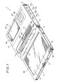
- Fig. 1 shows a portable computer 1 to which the present invention can be applied, and as shown in Fig. 1, this portable computer 1 is composed of a housing 3 in which main electrical sections and so on are housed and a display unit housing 5 foldably and unfoldably interconnected to the housing 3 by means of a hinge 9.
- the hinge 9 includes therein a flexible board (not shown) or the like for transmitting power, various signals or the like from the housing 3 side to the display unit housing 5 side via the flexible board.
- the housing 3 has a recess portion 3a which houses therein an input pen 11 and a cord 13 whose one end is coupled to the input pen 11.
- the cord 13 has at the other end thereof a connection terminal 13a which is connected to a terminal 15 provided on the side wall of the display unit housing 5.
- connection terminal 13a and the terminal 15 the input pen 11 is electrically connected to the portable computer 1.
- the display unit housing 5 has a display unit 7 formed of a liquid crystal display (LCD) device or the like, and an input tablet 20 formed of a transparent touch-sensitive device or the like is provided on a front surface of a display panel formed on the display unit 7.
- LCD liquid crystal display
- connection terminal 13a When the input pen 11 is moved on the surface of the input tablet 20 under the condition that the connection terminal 13a is connected to the terminal 15, electrostatic capacitance between the top of the input pen 11 and the tablet 20 is changed and an amount of the thus changed electrostatic capacitance is detected and output from the connection terminal 13a.
- the housing 3 also has a power switch 10 and has at portions shown by broken lines a socket 17 for receiving an IC card such as of a ROM (read only memory), a RAM (random access memory) or the like therein for expanding the function and an expansional socket 23 for connection to an external device (not shown).
- a power switch 10 has at portions shown by broken lines a socket 17 for receiving an IC card such as of a ROM (read only memory), a RAM (random access memory) or the like therein for expanding the function and an expansional socket 23 for connection to an external device (not shown).
- a power supply source 40 is housed in a recess portion provided with a lid 21 which can be opened and closed by releasing a lock mechanism 19.
- the display unit housing 5 also has a microphone 30 and audible signals input through the microphone 30 can be recorded (in a solid state recording fashion) and reproduced when predetermined switches on a switch pad 27 provided on the side wall of the housing 3 are operated.
- a recording switch 17a when a recording switch 17a is turned ON, the recording is started, and when a playback switch 17b is turned ON, then a recorded voice message is reproduced and emanated from a loudspeaker 25.
- a stop switch 17c When a stop switch 17c is turned ON, the recording or reproduction is stopped, and by operating a volume adjusting switch 17d, level of sound of reproduced voice message and so on can be adjusted.
- Fig. 2 shows in system block form a main electrical arrangement unit 100 of the portable computer 1.
- the entire operation of this electrical arrangement unit 100 is controlled by a control unit which mainly comprises a CPU (central processing unit) 102, a program ROM 104 and a working RAM 106.
- a control unit which mainly comprises a CPU (central processing unit) 102, a program ROM 104 and a working RAM 106.
- V-RAM video RAM
- output signals of the input tablet 20 and the input pen 11 are supplied through a tablet interface 118 to the CPU 102, and an output signal (audio signal) from the microphone 30 is supplied through a solid state recording processor section 120 to the CPU 120 and is thereby analog-to-digital (A/D) converted.
- the thus converted audio signal is stored in a backup RAM 108 to which a power supply source 110 is connected.
- a timer 111 is also energized by the power supply source 110, and the timer 111 counts the number of clocks obtained from a quartz oscillator 112 to thereby produce present data relative to year, month, date and time.
- a dialler circuit 122 When supplied with data of, for example, a phone number from the CPU 102, a dialler circuit 122 generates an audio signal corresponding to a dual tone signal transmitted to a telephone line network.
- An analog signal which results from digital-to-analog (D/A) converting the audio signal stored in the backup RAM 108 by the solid state recording processor section 120 or the dual tone signal generated from the dialler circuit 122 is output (emanated) from the loudspeaker 25 through a mixer 124.
- D/A digital-to-analog
- Outputs of the power supply switch 10 or the switch pad 27 are supplied through the power supply source 40 and a switch interface 124 to the CPU 102, and outputs of the IC card socket 17 and the expansional socket 23 are supplied respectively through an IC card interface 126 and an expansional interface 128 to the CPU 102.
- display process for displaying information on the display unit 7 and others are usual process (program) while unusual process might be pen coordinate correction process done when coordinate of the input pen 11 is considerably displaced and reset process for resetting the RAM 106 done when the CPU 102 is driven recklessly.
- the input tablet 20 is divided into two areas A and B and the pen coordinate correction process and the reset process for resetting the RAM 106 are assigned, respectively, to the two areas A and B.
- step S1 following the Start of operation in which the power supply switch 10 is turned ON, it is determined in decision step S1 whether or not the input pen 11 touches the tablet 20. If a NO is output at step S1, then the processing proceeds to step S4, whereat usual process is executed. If the power supply switch 10 is turned OFF as represented by a YES at decision step S5, then the processing is ended.
- step S1 the processing proceeds to the next decision step S3, whereat it is determined whether or not the point of the input pen 11 is brought in contact with particular area, that is, area A or B . If the point of the input pen 11 is brought in contact with the area A or B as represented by a YES at decision step S3, then the processing proceeds to step S10, whereat unusual process is executed.
- step S11 it is determined in decision step S11 whether or not the point of the input pen 11 is brought in contact with the area A . If a YES is output at decision step S11, then the processing proceeds to step S12, whereat the RAM 106 is reset. If a NO is output at step S11, then the processing proceeds to the next decision step S13, whereat it is determined whether or not the point of the input pen 11 is brought in contact with the area B . If a YES is output at decision step S13, then the processing proceeds to step S14, whereat unusual process, that is, the pen coordinate correction mode is executed. In this pen coordinate correction mode, a target (e.g.
- a cross-shaped mark is displayed on the display, and when the user touches the cross point of the cross-shaped mark with the point of the input pen 11, parallax data between the input coorindate to the input tablet 20 and a displayed picture is obtained. Thereafter, the input coordinate information can be corrected on the basis of the thus obtained data.
- a special mode for servicemen or the like may be considered as other unusual process. In that case, such special mode must be hidden from the user upon use and an area used to effect this special mode is preferably set in the input tablet 20 at its very small area of the corner. If a NO is output at decision step S13, then the unusual program is ended.
- step S10 if the power switch 10 is turned ON under the condition that the input pen 11 is in contact with any one of the areas A and B, then the unusual process is executed (see step S10).
- the portable computer 1 can be simplified in arrangement, made inexpensive and light in weight.
- the tablet 20 need not be divided into the two areas A and B and therefore the unusual process can be executed under the condition such that the input pen 11 is brought in contact with one portion of the tablet 20.
- the tablet 20 will be divided into a plurality of areas in response to the number of unusual processes.
- the input tablet 20 is not divided into a plurality of areas but the number of clicks done by the input pen 11 is made corresponding to the number of unusual processes uniquely so that, if the input pen 11 is clicked twice, the RAM 106 is reset and that if the input pen 11 is clicked three times, the unusual process of pen coordinate correction is executed.
- the above-mentioned condition that the input pen 11 is brought in contact with the input tablet 20 may be detected by various methods, such as detecting electrostatic capacitance under the condition that a switch provided on the point of pen is turned ON, detecting that a predetermined pressure is applied to a pressure sensitive tablet by a pen and so on.
- the input information processing apparatus includes the control section which executes the unusual process when the power switch is turned ON under the condition that the point of the input pen is brought in contact with the desired area of the input tablet.
Landscapes
- Engineering & Computer Science (AREA)
- Theoretical Computer Science (AREA)
- General Engineering & Computer Science (AREA)
- Physics & Mathematics (AREA)
- General Physics & Mathematics (AREA)
- Human Computer Interaction (AREA)
- Computing Systems (AREA)
- Computer Hardware Design (AREA)
- Position Input By Displaying (AREA)
- Calculators And Similar Devices (AREA)
Abstract
Description
- The present invention generally relates to input information processing apparatus and, more particularly, to an input information processing apparatus suitable for use with a portable computer or the like in which information is input from an input tablet provided on the surface side of a display panel by an input pen.
- Conventionally, as this kind of input information processing apparatus, a portable computer, for example, is known. The portable computer needs, in addition to usual process executed on the basis of various informations input by an input pen, unusual process such as pen coordinate correction, reset process for resetting a RAM (random access memory) when a CPU (central processing unit) is driven recklessly, initializing process of system and so on, and unusual process is executed when a plurality of switch buttons of various kinds of switch buttons provided on the portable computer are turned ON simultaneously.
- For example, in the initializing process of the system, under the condition that two switch buttons are pushed simultaneously, other switch button must be pushed. Further, in the correction process for correcting pen coordinate information input by the point of the pen, under the condition that one switch button is pushed, other switch button must be pushed.
- Further, in this kind of portable computer, it has been requested that the arrangement thereof is simplified, the manufacturing cost thereof is reduced and that the weight thereof is decreased.
- However, the number of various kinds of switch buttons must be reduced in order to simplify the arrangement of the portable computer, to reduce the manufacturing cost thereof and to reduce the weight thereof. On the contrary, the unusual process is executed by operating a plurality of switch buttons as described above, which hinders the portable computer from being simplified in arrangement, reduced in manufacturing cost and in weight.
- Accordingly, it is a general object of the present invention to provide an improved input information processing apparatus which can eliminate the aforenoted shortcomings and disadvantages encountered with the prior art.
- More specifically, it is an object of the present invention to provide an input information processing apparatus which can be simplified in arrangement.
- It is another object of the present invention to provide an input information processing apparatus which can be made inexpensive.
- It is a further object of the present invention to provide an input information processing apparatus which can be made light in weight.
- According to an aspect of the present invention, an input information processing apparatus is comprised of a pointing device for inputting coordinate information, a display unit for displaying input data by the input device, a tablet positioned on a display surface of the display unit for detecting the position pointed by the pointing device, and a control apparatus for judging whether or not the pointing device is placed down on the tablet when a power switch of the apparatus is operated so as to be placed in a power on condition after the control apparatus executes unusual process which is different from usual process.
- The above, and other objects, features and advantages of the present invention will become apparent in the following detailed description of an illustrative embodiment thereof to be taken in conjunction with the accompanying drawings, in which like reference numerals are used to identify the same or similar parts in the several views.
-
- Fig. 1 is a perspective view of an embodiment of an input information processing apparatus according to the present invention which is suitably applied to a portable computer;
- Fig. 2 is a systematic block diagram showing a main electrical arrangement of the portable computer shown in Fig. 1; and
- Figs. 3 and 4 are flowcharts, respectively, to which references will be made in explaining routines executed by a central processing unit of the portable computer shown in Fig. 1.
- An embodiment of an input information processing apparatus according to the present invention will hereinafter be described with reference to the accompanying drawings.
- Fig. 1 shows a portable computer 1 to which the present invention can be applied, and as shown in Fig. 1, this portable computer 1 is composed of a housing 3 in which main electrical sections and so on are housed and a
display unit housing 5 foldably and unfoldably interconnected to the housing 3 by means of ahinge 9. - The
hinge 9 includes therein a flexible board (not shown) or the like for transmitting power, various signals or the like from the housing 3 side to thedisplay unit housing 5 side via the flexible board. - The housing 3 has a recess portion 3a which houses therein an
input pen 11 and acord 13 whose one end is coupled to theinput pen 11. - The
cord 13 has at the other end thereof a connection terminal 13a which is connected to aterminal 15 provided on the side wall of thedisplay unit housing 5. By means of the connection terminal 13a and theterminal 15, theinput pen 11 is electrically connected to the portable computer 1. - The
display unit housing 5 has adisplay unit 7 formed of a liquid crystal display (LCD) device or the like, and aninput tablet 20 formed of a transparent touch-sensitive device or the like is provided on a front surface of a display panel formed on thedisplay unit 7. - When the
input pen 11 is moved on the surface of theinput tablet 20 under the condition that the connection terminal 13a is connected to theterminal 15, electrostatic capacitance between the top of theinput pen 11 and thetablet 20 is changed and an amount of the thus changed electrostatic capacitance is detected and output from the connection terminal 13a. - Even when the point of the
pen 11 is not in contact with thetablet 20, coordinate information of the point of thepen 11 is detected and a marker shaped as, for example, cross is displayed on the display panel of thedisplay unit 7 at its position in which the point of thepen 11 is opposed to thetablet 20. - The housing 3 also has a
power switch 10 and has at portions shown by broken lines asocket 17 for receiving an IC card such as of a ROM (read only memory), a RAM (random access memory) or the like therein for expanding the function and anexpansional socket 23 for connection to an external device (not shown). - A
power supply source 40 is housed in a recess portion provided with alid 21 which can be opened and closed by releasing alock mechanism 19. - Further, the
display unit housing 5 also has amicrophone 30 and audible signals input through themicrophone 30 can be recorded (in a solid state recording fashion) and reproduced when predetermined switches on aswitch pad 27 provided on the side wall of the housing 3 are operated. - More specifically, when a
recording switch 17a is turned ON, the recording is started, and when aplayback switch 17b is turned ON, then a recorded voice message is reproduced and emanated from aloudspeaker 25. - When a
stop switch 17c is turned ON, the recording or reproduction is stopped, and by operating avolume adjusting switch 17d, level of sound of reproduced voice message and so on can be adjusted. - Fig. 2 shows in system block form a main
electrical arrangement unit 100 of the portable computer 1. The entire operation of thiselectrical arrangement unit 100 is controlled by a control unit which mainly comprises a CPU (central processing unit) 102, aprogram ROM 104 and aworking RAM 106. - Under the control of the
CPU 102, display data is written in a V-RAM (video RAM) 116 through adisplay controller 114 and the display data is displayed on the display panel of thedisplay unit 7 via thedisplay controller 114 controlled by theCPU 102. - Further, output signals of the
input tablet 20 and theinput pen 11 are supplied through atablet interface 118 to theCPU 102, and an output signal (audio signal) from themicrophone 30 is supplied through a solid staterecording processor section 120 to theCPU 120 and is thereby analog-to-digital (A/D) converted. The thus converted audio signal is stored in abackup RAM 108 to which apower supply source 110 is connected. - A
timer 111 is also energized by thepower supply source 110, and thetimer 111 counts the number of clocks obtained from aquartz oscillator 112 to thereby produce present data relative to year, month, date and time. - When supplied with data of, for example, a phone number from the
CPU 102, adialler circuit 122 generates an audio signal corresponding to a dual tone signal transmitted to a telephone line network. - An analog signal, which results from digital-to-analog (D/A) converting the audio signal stored in the
backup RAM 108 by the solid staterecording processor section 120 or the dual tone signal generated from thedialler circuit 122 is output (emanated) from theloudspeaker 25 through amixer 124. - Outputs of the
power supply switch 10 or theswitch pad 27 are supplied through thepower supply source 40 and aswitch interface 124 to theCPU 102, and outputs of theIC card socket 17 and theexpansional socket 23 are supplied respectively through anIC card interface 126 and anexpansional interface 128 to theCPU 102. - Routines of processing done by the
CPU 102 will be explained next with reference to flowcharts of Figs. 3 and 4. - In this embodiment, display process for displaying information on the
display unit 7 and others are usual process (program) while unusual process might be pen coordinate correction process done when coordinate of theinput pen 11 is considerably displaced and reset process for resetting theRAM 106 done when theCPU 102 is driven recklessly. - As will be clear from Fig. 1, the
input tablet 20 is divided into two areas A and B and the pen coordinate correction process and the reset process for resetting theRAM 106 are assigned, respectively, to the two areas A and B. - Referring to Fig. 3, following the Start of operation in which the
power supply switch 10 is turned ON, it is determined in decision step S1 whether or not theinput pen 11 touches thetablet 20. If a NO is output at step S1, then the processing proceeds to step S4, whereat usual process is executed. If thepower supply switch 10 is turned OFF as represented by a YES at decision step S5, then the processing is ended. - On the other hand, if the
input pen 11 touches thetablet 20 as represented by a YES at decision step S1, then the processing proceeds to the next decision step S3, whereat it is determined whether or not the point of theinput pen 11 is brought in contact with particular area, that is, area A or B. If the point of theinput pen 11 is brought in contact with the area A or B as represented by a YES at decision step S3, then the processing proceeds to step S10, whereat unusual process is executed. - Referring to Fig. 4, following the step S10 of unusual program, it is determined in decision step S11 whether or not the point of the
input pen 11 is brought in contact with the area A. If a YES is output at decision step S11, then the processing proceeds to step S12, whereat theRAM 106 is reset. If a NO is output at step S11, then the processing proceeds to the next decision step S13, whereat it is determined whether or not the point of theinput pen 11 is brought in contact with the area B. If a YES is output at decision step S13, then the processing proceeds to step S14, whereat unusual process, that is, the pen coordinate correction mode is executed. In this pen coordinate correction mode, a target (e.g. a cross-shaped mark) is displayed on the display, and when the user touches the cross point of the cross-shaped mark with the point of theinput pen 11, parallax data between the input coorindate to theinput tablet 20 and a displayed picture is obtained. Thereafter, the input coordinate information can be corrected on the basis of the thus obtained data. - A special mode for servicemen or the like may be considered as other unusual process. In that case, such special mode must be hidden from the user upon use and an area used to effect this special mode is preferably set in the
input tablet 20 at its very small area of the corner. If a NO is output at decision step S13, then the unusual program is ended. - In that event, at the completion of processing at steps S12 and S14, the unusual process is ended and the processing returns to step S1 of Fig. 3, and the following steps are executed similarly as described above.
- As described above, according to this embodiment, if the
power switch 10 is turned ON under the condition that theinput pen 11 is in contact with any one of the areas A and B, then the unusual process is executed (see step S10). - Accordingly, since the unusual process need not be executed by operating a plurality of operation switch buttons and hence the number of such switch buttons is reduced, the portable computer 1 can be simplified in arrangement, made inexpensive and light in weight.
- If there is a single unusual process, the
tablet 20 need not be divided into the two areas A and B and therefore the unusual process can be executed under the condition such that theinput pen 11 is brought in contact with one portion of thetablet 20. On the other hand, if there are more than three unusual processes, thetablet 20 will be divided into a plurality of areas in response to the number of unusual processes. - Alternatively, when there are a plurality of unusual processes, the
input tablet 20 is not divided into a plurality of areas but the number of clicks done by theinput pen 11 is made corresponding to the number of unusual processes uniquely so that, if theinput pen 11 is clicked twice, theRAM 106 is reset and that if theinput pen 11 is clicked three times, the unusual process of pen coordinate correction is executed. - Incidentally, the above-mentioned condition that the
input pen 11 is brought in contact with theinput tablet 20 may be detected by various methods, such as detecting electrostatic capacitance under the condition that a switch provided on the point of pen is turned ON, detecting that a predetermined pressure is applied to a pressure sensitive tablet by a pen and so on. - As will be understood from the aforenoted explanation, the input information processing apparatus according to the present invention includes the control section which executes the unusual process when the power switch is turned ON under the condition that the point of the input pen is brought in contact with the desired area of the input tablet.
- Accordingly, when the unusual process is executed, such unusual process is executed only by operating the input pen and the power switch. As a consequence, the number of various switch buttons provided in the input information processing apparatus can be reduced, which can provide the simplified, inexpensive and light-weighed input information processing apparatus.
- Having described a preferred embodiment of the invention with reference to the accompanying drawings, it is to be understood that the invention is not limited to that precise embodiment and that various changes and modifications thereof could be effected by one skilled in the art without departing from the spirit or scope of the novel concepts of the invention as defined in the appended claims.
Claims (7)
- An input information processing apparatus comprising:(a) pointing means for inputting coordinate information;(b) display means for displaying input data by said input means;(c) tablet means positioned on a display surface of said display means for detecting the position pointed by said pointing means; and(d) control means for judging whether or not said pointing means is placed down on said tablet means when a power switch of said apparatus is operated so as to be placed in a power on condition and then said control means executes unusual process which is different from usual process.
- An input information processing apparatus according to claim 1, wherein said pointing means is a pen for inputting an information.
- An input information processing apparatus according to claim 2, wherein said unusual process is an initializing process of said apparatus.
- An input information processing apparatus according to claim 2, wherein said unusual process is a resetting process of memory means for storing data by said pen.
- An input information processing apparatus according to claim 2, wherein said pen has a point of pen to input data when the point of pen is placed down on said tablet means.
- An input information processing apparatus according to claim 1, wherein said tablet means is divided into a plurality of areas for executing each different process.
- An input information processing apparatus according to any one of preceding claims, wherein said apparatus is a portable computer.
Applications Claiming Priority (2)
| Application Number | Priority Date | Filing Date | Title |
|---|---|---|---|
| JP42062/90 | 1990-02-22 | ||
| JP04206290A JP3200058B2 (en) | 1990-02-22 | 1990-02-22 | Information input control device |
Publications (3)
| Publication Number | Publication Date |
|---|---|
| EP0448225A2 true EP0448225A2 (en) | 1991-09-25 |
| EP0448225A3 EP0448225A3 (en) | 1992-05-27 |
| EP0448225B1 EP0448225B1 (en) | 1995-12-13 |
Family
ID=12625616
Family Applications (1)
| Application Number | Title | Priority Date | Filing Date |
|---|---|---|---|
| EP91301315A Expired - Lifetime EP0448225B1 (en) | 1990-02-22 | 1991-02-20 | Input information processing apparatus using pointing means |
Country Status (4)
| Country | Link |
|---|---|
| EP (1) | EP0448225B1 (en) |
| JP (1) | JP3200058B2 (en) |
| KR (1) | KR100225439B1 (en) |
| DE (1) | DE69115316T2 (en) |
Cited By (2)
| Publication number | Priority date | Publication date | Assignee | Title |
|---|---|---|---|---|
| EP0498307A3 (en) * | 1991-02-04 | 1995-02-01 | Sony Corp | |
| CN102621728A (en) * | 2011-01-28 | 2012-08-01 | 宏达国际电子股份有限公司 | Touch device with shielding layer |
Family Cites Families (2)
| Publication number | Priority date | Publication date | Assignee | Title |
|---|---|---|---|---|
| DE3586927T2 (en) * | 1984-04-20 | 1993-06-03 | Hitachi Ltd | FLAT SCREEN DISPLAY SYSTEM WITH INTEGRATED INPUT DEVICE. |
| JPS61120231A (en) * | 1984-11-16 | 1986-06-07 | Sharp Corp | Handwriting input device |
-
1990
- 1990-02-22 JP JP04206290A patent/JP3200058B2/en not_active Expired - Fee Related
-
1991
- 1991-02-20 DE DE69115316T patent/DE69115316T2/en not_active Expired - Fee Related
- 1991-02-20 EP EP91301315A patent/EP0448225B1/en not_active Expired - Lifetime
- 1991-02-20 KR KR1019910002695A patent/KR100225439B1/en not_active Expired - Fee Related
Cited By (3)
| Publication number | Priority date | Publication date | Assignee | Title |
|---|---|---|---|---|
| EP0498307A3 (en) * | 1991-02-04 | 1995-02-01 | Sony Corp | |
| CN102621728A (en) * | 2011-01-28 | 2012-08-01 | 宏达国际电子股份有限公司 | Touch device with shielding layer |
| CN102621728B (en) * | 2011-01-28 | 2014-12-24 | 宏达国际电子股份有限公司 | Touch device with shielding layer |
Also Published As
| Publication number | Publication date |
|---|---|
| EP0448225A3 (en) | 1992-05-27 |
| JPH03244016A (en) | 1991-10-30 |
| DE69115316D1 (en) | 1996-01-25 |
| EP0448225B1 (en) | 1995-12-13 |
| KR100225439B1 (en) | 1999-10-15 |
| JP3200058B2 (en) | 2001-08-20 |
| KR920000031A (en) | 1992-01-10 |
| DE69115316T2 (en) | 1996-10-10 |
Similar Documents
| Publication | Publication Date | Title |
|---|---|---|
| US5406307A (en) | Data processing apparatus having simplified icon display | |
| US4853682A (en) | Data stored display device | |
| US5670992A (en) | Portable graphic computer apparatus | |
| JP2004040352A (en) | Portable information communication terminal, program, and recording medium recording the program | |
| JPH03280119A (en) | Tabletop electronic calculator | |
| US20050145774A1 (en) | Apparatus and method for operating and controlling display and backlight in portable terminals | |
| EP0448225A2 (en) | Input information processing apparatus using pointing means | |
| EP0445906A1 (en) | Cursor display control in a hand-written information apparatus | |
| JPH08297660A (en) | Input device for chinese character | |
| JP2785194B2 (en) | Personal information management method and device | |
| JP3163623B2 (en) | Information equipment | |
| KR960015179B1 (en) | Function input device and method of touch panel remote controller | |
| JP3138268B2 (en) | Automatic dial transmission method and automatic dial transmission device | |
| KR100809965B1 (en) | Apparatus for remote resource access and remote interface | |
| JP3181133B2 (en) | Electrical equipment | |
| JPH02214354A (en) | Card type multi-functional telephone terminal system | |
| JP3321803B2 (en) | Information input control device and information input control method | |
| JPH09231178A (en) | Electronic memo device | |
| US20100120472A1 (en) | Mobile terminal and key code setting method of mobile terminal | |
| JP3109108B2 (en) | Time setting device and method, and electronic device | |
| KR100257578B1 (en) | Time setting method of a vcr and remote controller | |
| KR200309247Y1 (en) | A portable player of conversing fuction | |
| JPH01286013A (en) | Touch panel device | |
| JPH07129613A (en) | Electronic reading device | |
| JP2653145B2 (en) | Automatic dialing device |
Legal Events
| Date | Code | Title | Description |
|---|---|---|---|
| PUAI | Public reference made under article 153(3) epc to a published international application that has entered the european phase |
Free format text: ORIGINAL CODE: 0009012 |
|
| AK | Designated contracting states |
Kind code of ref document: A2 Designated state(s): DE FR GB |
|
| PUAL | Search report despatched |
Free format text: ORIGINAL CODE: 0009013 |
|
| AK | Designated contracting states |
Kind code of ref document: A3 Designated state(s): DE FR GB |
|
| 17P | Request for examination filed |
Effective date: 19921005 |
|
| 17Q | First examination report despatched |
Effective date: 19931206 |
|
| GRAA | (expected) grant |
Free format text: ORIGINAL CODE: 0009210 |
|
| AK | Designated contracting states |
Kind code of ref document: B1 Designated state(s): DE FR GB |
|
| REF | Corresponds to: |
Ref document number: 69115316 Country of ref document: DE Date of ref document: 19960125 |
|
| ET | Fr: translation filed | ||
| PLBE | No opposition filed within time limit |
Free format text: ORIGINAL CODE: 0009261 |
|
| STAA | Information on the status of an ep patent application or granted ep patent |
Free format text: STATUS: NO OPPOSITION FILED WITHIN TIME LIMIT |
|
| 26N | No opposition filed | ||
| REG | Reference to a national code |
Ref country code: GB Ref legal event code: IF02 |
|
| PGFP | Annual fee paid to national office [announced via postgrant information from national office to epo] |
Ref country code: FR Payment date: 20020212 Year of fee payment: 12 |
|
| PGFP | Annual fee paid to national office [announced via postgrant information from national office to epo] |
Ref country code: GB Payment date: 20020220 Year of fee payment: 12 |
|
| PGFP | Annual fee paid to national office [announced via postgrant information from national office to epo] |
Ref country code: DE Payment date: 20020306 Year of fee payment: 12 |
|
| PG25 | Lapsed in a contracting state [announced via postgrant information from national office to epo] |
Ref country code: GB Free format text: LAPSE BECAUSE OF NON-PAYMENT OF DUE FEES Effective date: 20030220 |
|
| PG25 | Lapsed in a contracting state [announced via postgrant information from national office to epo] |
Ref country code: DE Free format text: LAPSE BECAUSE OF NON-PAYMENT OF DUE FEES Effective date: 20030902 |
|
| GBPC | Gb: european patent ceased through non-payment of renewal fee | ||
| PG25 | Lapsed in a contracting state [announced via postgrant information from national office to epo] |
Ref country code: FR Free format text: LAPSE BECAUSE OF NON-PAYMENT OF DUE FEES Effective date: 20031031 |
|
| REG | Reference to a national code |
Ref country code: FR Ref legal event code: ST |