EP0455556B1 - Gedämpfte elastische Kupplungsvorrichtung zwischen zwei koaxialen drehenden Scheiben - Google Patents
Gedämpfte elastische Kupplungsvorrichtung zwischen zwei koaxialen drehenden Scheiben Download PDFInfo
- Publication number
- EP0455556B1 EP0455556B1 EP91401151A EP91401151A EP0455556B1 EP 0455556 B1 EP0455556 B1 EP 0455556B1 EP 91401151 A EP91401151 A EP 91401151A EP 91401151 A EP91401151 A EP 91401151A EP 0455556 B1 EP0455556 B1 EP 0455556B1
- Authority
- EP
- European Patent Office
- Prior art keywords
- elastic
- discs
- supports
- disc
- composite material
- Prior art date
- Legal status (The legal status is an assumption and is not a legal conclusion. Google has not performed a legal analysis and makes no representation as to the accuracy of the status listed.)
- Expired - Lifetime
Links
Images

Classifications
-
- F—MECHANICAL ENGINEERING; LIGHTING; HEATING; WEAPONS; BLASTING
- F16—ENGINEERING ELEMENTS AND UNITS; GENERAL MEASURES FOR PRODUCING AND MAINTAINING EFFECTIVE FUNCTIONING OF MACHINES OR INSTALLATIONS; THERMAL INSULATION IN GENERAL
- F16D—COUPLINGS FOR TRANSMITTING ROTATION; CLUTCHES; BRAKES
- F16D3/00—Yielding couplings, i.e. with means permitting movement between the connected parts during the drive
- F16D3/50—Yielding couplings, i.e. with means permitting movement between the connected parts during the drive with the coupling parts connected by one or more intermediate members
- F16D3/60—Yielding couplings, i.e. with means permitting movement between the connected parts during the drive with the coupling parts connected by one or more intermediate members comprising pushing or pulling links attached to both parts
- F16D3/62—Yielding couplings, i.e. with means permitting movement between the connected parts during the drive with the coupling parts connected by one or more intermediate members comprising pushing or pulling links attached to both parts the links or their attachments being elastic
-
- F—MECHANICAL ENGINEERING; LIGHTING; HEATING; WEAPONS; BLASTING
- F16—ENGINEERING ELEMENTS AND UNITS; GENERAL MEASURES FOR PRODUCING AND MAINTAINING EFFECTIVE FUNCTIONING OF MACHINES OR INSTALLATIONS; THERMAL INSULATION IN GENERAL
- F16D—COUPLINGS FOR TRANSMITTING ROTATION; CLUTCHES; BRAKES
- F16D3/00—Yielding couplings, i.e. with means permitting movement between the connected parts during the drive
- F16D3/50—Yielding couplings, i.e. with means permitting movement between the connected parts during the drive with the coupling parts connected by one or more intermediate members
-
- F—MECHANICAL ENGINEERING; LIGHTING; HEATING; WEAPONS; BLASTING
- F16—ENGINEERING ELEMENTS AND UNITS; GENERAL MEASURES FOR PRODUCING AND MAINTAINING EFFECTIVE FUNCTIONING OF MACHINES OR INSTALLATIONS; THERMAL INSULATION IN GENERAL
- F16D—COUPLINGS FOR TRANSMITTING ROTATION; CLUTCHES; BRAKES
- F16D3/00—Yielding couplings, i.e. with means permitting movement between the connected parts during the drive
- F16D3/50—Yielding couplings, i.e. with means permitting movement between the connected parts during the drive with the coupling parts connected by one or more intermediate members
- F16D3/56—Yielding couplings, i.e. with means permitting movement between the connected parts during the drive with the coupling parts connected by one or more intermediate members comprising elastic metal lamellae, elastic rods, or the like, e.g. arranged radially or parallel to the axis, the members being shear-loaded collectively by the total load
- F16D3/58—Yielding couplings, i.e. with means permitting movement between the connected parts during the drive with the coupling parts connected by one or more intermediate members comprising elastic metal lamellae, elastic rods, or the like, e.g. arranged radially or parallel to the axis, the members being shear-loaded collectively by the total load the intermediate members being made of rubber or like material
-
- F—MECHANICAL ENGINEERING; LIGHTING; HEATING; WEAPONS; BLASTING
- F16—ENGINEERING ELEMENTS AND UNITS; GENERAL MEASURES FOR PRODUCING AND MAINTAINING EFFECTIVE FUNCTIONING OF MACHINES OR INSTALLATIONS; THERMAL INSULATION IN GENERAL
- F16D—COUPLINGS FOR TRANSMITTING ROTATION; CLUTCHES; BRAKES
- F16D3/00—Yielding couplings, i.e. with means permitting movement between the connected parts during the drive
- F16D3/50—Yielding couplings, i.e. with means permitting movement between the connected parts during the drive with the coupling parts connected by one or more intermediate members
- F16D3/72—Yielding couplings, i.e. with means permitting movement between the connected parts during the drive with the coupling parts connected by one or more intermediate members with axially-spaced attachments to the coupling parts
- F16D3/725—Yielding couplings, i.e. with means permitting movement between the connected parts during the drive with the coupling parts connected by one or more intermediate members with axially-spaced attachments to the coupling parts with an intermediate member made of fibre-reinforced resin
Definitions
- the invention relates to a damped elastic coupling device between two driving and driven discs, coaxial and parallel rotating, the driving disc being intended to drive the driven disc in rotation in one direction or the other so that the transmission of the torque drive can be done gradually at least within a determined angular range, each of said discs comprising for this purpose at least one support for the end of an elastic element for transmitting the torque, consisting essentially of a composite material with modulus relatively high elasticity, associated with an elastic damping mass.
- the problem underlying the invention is to ensure that one of the rotating discs can transmit its torque to the other gradually, namely elastically, with a damping which prevents transmission of the vibrations from the disc leading to the disc. led.
- a coupling device of the general type defined at the start will, in accordance with the present invention, be mainly characterized in that said composite material is in the form of at least one blade or of a set of parallel blades embedded in said elastic damping mass and oriented in such a way, between the corresponding supports, respectively integral with the driving disc and the driven disc, that the transmission of the torque between these discs is essentially operated by bending said blades, and damping by shearing said elastic mass, the latter being for this purpose adhered to said blades as well as said supports.
- said elastic element has a sandwich structure, the number of blades with high modulus of elasticity - ensuring the effect of spring - coated by the elastic damping mass, which can moreover be arbitrary.
- This bending of the composite blades generates a reaction which ensures the progressiveness of the variation of the transmitted torque.
- the shearing of the elastic mass between the blades also makes it possible to obtain excellent damping of the fluctuations of the torque, and therefore to limit the transmission of vibrations.
- the flexion of the blades can be obtained different ways. The simplest is to make these blades work like beams anchored at their two ends and damped.
- a device according to the present invention can also be characterized in that said supports are offset radially with respect to each other, said blades extending essentially in the radial direction.
- the composite blades can also be preformed into an arc or the like, which still allows them to work in bending.
- a device according to the invention can also be characterized in that said supports are angularly offset with respect to each other, said blades extending essentially in an arcuate form between these supports.
- said elastic elements and in particular said elastic mass of these elements, are shaped so as to allow the flexural deformation of said elements with uniformity. constraints, and that these same supports are also established, in an arcuate or similar form, to adapt to the deformation of said elastic elements.
- said composite material is essentially based on glass fibers, impregnated with a thermosetting resin of epoxy type. or vinyl ester, and that said elastic mass is constituted by an elastomer such as natural rubber or synthetic rubber based on butyl, EPDM or SBR (with styrol butadiene).
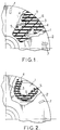
- the coaxial rotating discs which it is a question of coupling elastically and in a damped way, one being leading and the other driven, have been referenced 1 and 2.
- It is two flat metal discs, coaxial and parallel. Their relative direction of rotation is indifferent.
- the supports for the ends of the elastic coupling elements have been referenced 4 for the lower disc 1 and 5 for the upper disc 2, which is partially torn off.
- the supports 4 and 5 have a particular shape (arcuate) adapted to the potential bending deformations of the elastic element. It is the same for the elastic mass 6 of this element, for example of the natural rubber, which coats, by being adhered to it, these same supports 4 and 5 as well as the radial blades of composite material 3 (glass fibers or the like coated in a thermosetting polymerized resin).
- the elastic element 3-6 will work mainly in bending during the progressive phase of transmission of the engine torque between the driving disc and the driven disc, this with excellent damping, due to the shearing of the rubber between the blades .
- the same materials as above can be used to make the elastic elements 3, 6.
- the blades 3 still work in bending, but in the manner of an arc, the extreme metal supports 4 ( secured to the disc 1) and 5 (secured to the disc 2) being angularly offset with respect to each other; damping is also obtained by shearing of the elastic mass 6, and limitation of the angular displacement by the stop 7.
- the elastic elements 3, 6 will be in sufficient number (for example four in number) to ensure the transmission of the torque, and will be arranged at equal angular spacings on discs for balancing the masses.
- the composite blades 3 may have a thickness of the order of 2 mm and a width of the order of 16 mm.
- said elastic rotational connecting elements in any other form, by example in the form of a solid disc (or disc sectors) coaxial bonded between the two rotating discs, this disc can incorporate composite reinforcements in the form of rods. They could also be constituted in the form of a section of elliptical tube 3 or the like, made of composite material. This tube could be mounted between the respective supports 4, 5 of the rotating disks in a similar manner to that of the embodiment of FIG. 2, its opposite walls being connected internally by an elastic damping mass 6.
- FIGS. 3 and 4 Such an embodiment has been represented in FIGS. 3 and 4. It can be seen in FIG. 3 that these supports 4, 5 have been formed in the form of a kind of staples passing inside the tube 3 and crimped on discs 1 and 2 respectively.
Landscapes
- Engineering & Computer Science (AREA)
- General Engineering & Computer Science (AREA)
- Mechanical Engineering (AREA)
- Mechanical Operated Clutches (AREA)
- Springs (AREA)
- Vibration Dampers (AREA)
Claims (11)
- Gedämpfte elastische Kupplungsvorrichtung zwischen zwei sich drehenden Scheiben (1, 2), von denen die eine treibend und die andere angetrieben ist und die koaxial und parallel zueinander angeordnet sind, wobei die treibende Scheibe (1) dazu dient, die angetriebene Scheibe in beiden Richtungen drehend anzutreiben, so daß die Übertragung des Antriebsdrehmomentes progressiv wenigstens in einem bestimmten Winkelbereich erfolgen kann und beide Scheiben (1, 2) zu diesem Zweck wenigstens eine Abstützung (4, 5) für das Ende eines elastischen Elementes zur Übertragung des Drehmomentes enthalten, das im wesentlichen aus einem zusammengesetzten Material (3) mit einem verhältnismäßig hohen Elastizitätsmodul besteht, das mit einer elastischen Dämpfungsmasse verbunden ist, dadurch gekennzeichnet, daß das zusammengesetzte Material (3) in Form wenigstens einer Lamelle oder einer Anordnung von parallelen Lamellen vorliegt, die in die elastische Dämpfungsmasse (6) eingebettet und zwischen den entsprechenden Abstützungen (4, 5), die an der treibenden Scheibe (1) bzw. der angetriebenen Scheibe (2) befestigt sind, so ausgerichtet sind, daß die Übertragung des Drehmomentes zwischen den Scheiben (1, 2) im wesentlichen durch eine Biegung der Lamellen und die Dämpfung durch eine Scherbeanspruchung der elastischen Masse erfolgt, die zu diesem Zweck sowohl an den Lamellen als auch an den Abstützungen (4, 5) angebracht ist.
- Kupplungsvorrichtung nach Anspruch 1, dadurch gekennzeichnet, daß die Abstützungen (4, 5) in radialer Richtung zueinander versetzt sind und die Lamellen (3) sich im wesentlichen in radialer Richtung erstrecken.
- Kupplungsvorrichtung nach Anspruch 1, dadurch gekennzeichnet, daß die Abstützungen (4, 5) winklig zueinander versetzt sind und daß sich die Lamellen (3) im wesentlichen bogenförmig zwischen diesen Abstützungen erstrecken.
- Kupplungsvorrichtung nach einem der vorhergehenden Ansprüche, dadurch gekennzeichnet, daß an einer der beiden sich drehenden Scheiben (1, 2) an geeigneten Stellen Anschläge (7) zur Begrenzung der relativen Winkelschwingung der Scheiben vorgesehen sind.
- Kupplungsvorrichtung nach einem der Ansprüche i bis 4, dadurch gekennzeichnet, daß die elastischen Elemente und insbesondere die elastische Masse (6) der Elemente so ausgebildet sind, daß sie die Biegeverformung der Elemente (3, 6) mit einer Vergleichmäßigung der Spannungen ermöglichen.
- Vorrichtung nach Anspruch 5, dadurch gekennzeichnet, daß die Abstützungen (4, 5) ebenfalls bogenförmig oder ähnlich ausgebildet sind, um sich der Verformung der elastischen Elemente (3, 6) anzupassen.
- Kupplungsvorrichtung nach einem der vorhergehenden Ansprüche, dadurch gekennzeichnet, daß das zusammengesetzte Material (3) im wesentlichen auf der Basis von Glasfasern gebildet ist, die mit einem in der Wärme aushärtbaren Harz vom Typ eines Epoxyds oder Vinylesters imprägniert sind.
- Vorrichtung nach einem der vorhergehenden Ansprüche, dadurch gekennzeichnet, daß die elastische Masse (6) aus einem elastomeren Material aus natürlichem oder synthetischen Kautschuk besteht.
- Vorrichtung nach einem der vorhergehenden Ansprüche 1 bis 7, dadurch gekennzeichnet, daß die elastische Masse (6) auf der Basis von Butylkautschuk, EPDM oder SBR ist.
- Gedämpfte elastische Kupplungsvorrichtung zwischen zwei sich drehenden Scheiben (1, 2), von denen die eine treibend und die andere angetrieben ist und die koaxial und parallel zueinander angeordnet sind, wobei die treibende Scheibe (1) dazu dient, die angetriebene Scheibe in beiden Richtungen drehend anzutreiben, so daß die Übertragung des Antriebsdrehmomentes progressiv wenigstens in einem bestimmten Winkelbereich erfolgen kann und beide Scheiben (1, 2) zu diesem Zweck wenigstens eine Abstützung (4, 5) für das Ende eines elastischen Elementes zur Übertragung des Drehmomentes enthalten, das im wesentlichen aus einem zusammengesetzten Material (3) mit einem verhältnismäßig hohen Elastizitätsmodul besteht, das mit einer elastischen Dämpfungsmasse verbunden ist, dadurch gekennzeichnet, daß das elastische Element die Form einer koaxialen vollen Scheibe (oder Sektoren der Scheibe) hat, die gegebenenfalls mit einem zusammensesetzten Material verstärkt und zwischen den sich drehenden Scheiben befestigt ist, wobei die Abstützungen dann aus den Oberflächen bestehen, die den Scheiben gegenüberliegen.
- Vorrichtung nach Anspruch 10, dadurch gekennzeichnet, daß das elastische Element die Form eines Rohrstückes (3) aus zusammengesetzten Material hat, das zwischen zwei Abstützungen (4, 5) der sich drehenden Scheiben befestigt ist, wobei die beiden entgegengesetzten Wandungen des Rohrstückes innen über eine elastische Dämpfungsmasse (6) verbunden sind.
Applications Claiming Priority (2)
| Application Number | Priority Date | Filing Date | Title |
|---|---|---|---|
| FR9005666A FR2661720B1 (fr) | 1990-05-04 | 1990-05-04 | Dispositif d'accouplement elastique amorti entre deux parties tournantes coaxiales. |
| FR9005666 | 1990-05-04 |
Publications (2)
| Publication Number | Publication Date |
|---|---|
| EP0455556A1 EP0455556A1 (de) | 1991-11-06 |
| EP0455556B1 true EP0455556B1 (de) | 1994-06-01 |
Family
ID=9396354
Family Applications (1)
| Application Number | Title | Priority Date | Filing Date |
|---|---|---|---|
| EP91401151A Expired - Lifetime EP0455556B1 (de) | 1990-05-04 | 1991-04-30 | Gedämpfte elastische Kupplungsvorrichtung zwischen zwei koaxialen drehenden Scheiben |
Country Status (5)
| Country | Link |
|---|---|
| US (1) | US5211606A (de) |
| EP (1) | EP0455556B1 (de) |
| JP (1) | JPH0777221A (de) |
| DE (1) | DE69102200T2 (de) |
| FR (1) | FR2661720B1 (de) |
Families Citing this family (6)
| Publication number | Priority date | Publication date | Assignee | Title |
|---|---|---|---|---|
| FR2687197B1 (fr) * | 1992-02-11 | 1994-05-13 | Commerce Internal Echange Tech | Liaison amortissante simplifiee, procede de fabrication d'une telle liaison, ensemble de liaison comportant une pluralite de telles liaisons et accouplement comportant au moins une telle liaison. |
| JP2596676B2 (ja) * | 1992-07-09 | 1997-04-02 | 株式会社ケイセブン | 軸継手 |
| DE4243447A1 (de) * | 1992-12-22 | 1994-06-23 | Huels Chemische Werke Ag | Kupplungselement zum Übertragen von Drehmomenten und Verfahren zu dessen Herstellung |
| US6342273B1 (en) | 1994-11-16 | 2002-01-29 | Dsm N.V. | Process for coating a substrate with a powder paint composition |
| AT409165B (de) * | 2000-06-15 | 2002-06-25 | Ellergon Antriebstech Gmbh | Drehelastische kupplung |
| JP3726967B2 (ja) * | 2003-11-27 | 2005-12-14 | 川崎重工業株式会社 | 圧縮型弾性継手のゴムエレメント |
Family Cites Families (12)
| Publication number | Priority date | Publication date | Assignee | Title |
|---|---|---|---|---|
| US2073852A (en) * | 1935-05-31 | 1937-03-16 | Caterpillar Tractor Co | Drive connecting link |
| FR1295753A (fr) * | 1961-07-20 | 1962-06-08 | Dispositif d'accouplement semi-élastique | |
| US3354670A (en) * | 1965-09-03 | 1967-11-28 | Fawick Corp | Flexible coupling |
| FR1496200A (fr) * | 1966-08-17 | 1967-09-29 | Luxembourg Brev Participations | Perfectionnements apportés aux accouplements élastiques |
| US3747367A (en) * | 1971-12-23 | 1973-07-24 | Ford Motor Co | Bellows flexible joint |
| DE2705295C2 (de) * | 1977-02-09 | 1982-08-12 | Bayerische Motoren Werke AG, 8000 München | Elastische Wellenkupplung |
| US4391594A (en) * | 1980-08-25 | 1983-07-05 | Lord Corporation | Flexible coupling |
| DE3108007C2 (de) * | 1981-03-03 | 1984-03-01 | Messerschmitt-Bölkow-Blohm GmbH, 8000 München | Elastische Wellenkupplung |
| GB8316732D0 (en) * | 1983-06-20 | 1983-07-20 | Secretary Industry Brit | Zone-stiffened composites |
| FR2557656B1 (fr) * | 1983-12-30 | 1988-05-27 | Valeo | Dispositif amortisseur de torsion a organe elastique de centrage, notamment pour embrayage de vehicule automobile |
| DE3441008C1 (de) * | 1984-11-09 | 1986-02-06 | Centa Antriebe Dipl.-Ing. G. Kirschey GmbH & Co KG, 5657 Haan | Hochelastische Wellenkupplung |
| DE8811849U1 (de) * | 1988-03-18 | 1989-07-13 | Dipl.-Ing. Herwarth Reich GmbH, Maschinenfabrik, 4630 Bochum | Drehelastische Wellenkupplung |
-
1990
- 1990-05-04 FR FR9005666A patent/FR2661720B1/fr not_active Expired - Lifetime
-
1991
- 1991-04-30 DE DE69102200T patent/DE69102200T2/de not_active Expired - Fee Related
- 1991-04-30 JP JP3128704A patent/JPH0777221A/ja active Pending
- 1991-04-30 EP EP91401151A patent/EP0455556B1/de not_active Expired - Lifetime
- 1991-05-06 US US07/694,976 patent/US5211606A/en not_active Expired - Lifetime
Also Published As
| Publication number | Publication date |
|---|---|
| EP0455556A1 (de) | 1991-11-06 |
| FR2661720A1 (fr) | 1991-11-08 |
| JPH0777221A (ja) | 1995-03-20 |
| FR2661720B1 (fr) | 1995-04-28 |
| US5211606A (en) | 1993-05-18 |
| DE69102200D1 (de) | 1994-07-07 |
| DE69102200T2 (de) | 1995-01-12 |
Similar Documents
| Publication | Publication Date | Title |
|---|---|---|
| EP0251849B1 (de) | Dämpfendes Schwungrad, insbesondere für die Drehmomentübertragung | |
| FR2749365A1 (fr) | Amortisseur d'oscillations en torsion | |
| FR2611013A1 (fr) | Dispositif amortisseur de torsion comprenant au moins un bras elastiquement deformable | |
| FR2554886A1 (fr) | Plateau d'embrayage pour embrayage a friction de vehicule automobile | |
| EP0236159A1 (de) | Schwingungsdämpfer für Kraftfahrzeuge | |
| FR2664667A1 (fr) | Dispositif d'amortissement de vibrations. | |
| EP0211701A1 (de) | Drehschwingungsdämpfer, insbesondere für Kraftfahrzeugkupplung, wobei die Dämpfung wenigstens teilweise durch ein Elastomerelement erzeugt wird | |
| EP0258113B1 (de) | Torsionsdämpfeinrichtung mit zwei koaxial zueinander angeordneten Teilen, die unter umfangsgerichtet wirkenden Schraubenfedern besteht | |
| FR2663707A1 (fr) | Dispositif amortisseur de torsion, notamment pour disque de friction d'embrayage de vehicule automobile. | |
| EP0455556B1 (de) | Gedämpfte elastische Kupplungsvorrichtung zwischen zwei koaxialen drehenden Scheiben | |
| FR2766537A1 (fr) | Amortisseur d'oscillation de torsion | |
| EP0697075A1 (de) | Torsionsschwingungsvordämpfer, insbesondere für kraftfahrzeuge | |
| FR2763658A1 (fr) | Embrayage centrifuge dont les masselottes portent des machoires cooperant par friction avec un tambour | |
| EP1358412B1 (de) | Reibscheibe und verfahren zur herstellung | |
| FR2801081A1 (fr) | Amortisseur de torsion pour embrayage a friction, en particulier pour vehicule automobile | |
| FR2598477A1 (fr) | Poulie de variateur de vitesse et variateur de vitesse incorporant une telle poulie. | |
| WO2005071279A1 (fr) | Embrayage a friction, notamment pour vehicule automobile, comportant des moyens de frottement differencies. | |
| FR2557661A1 (fr) | Poulie de variateur de vitesse a commande centrifuge | |
| FR2862730A1 (fr) | Amortisseur de torsion pour dispositif de transmission de couple | |
| EP0851147A1 (de) | Reibungsring und Vorrichtung für Drehschwingungsdämpfung, insbesondere Kraftfahrzeuge die einen solchen Ring benutzen | |
| EP0762000B1 (de) | Verbindungs- und Kraftübertragungsvorrichtung zwischen zwei koaxialen drehenden Teilen | |
| EP0833075B1 (de) | Torsionsdämpfer mit Fingern für Getriebeelement, insbesondere Reibungskupplung eines Fahrzeugs | |
| WO2001013012A1 (fr) | Transmission automatique d'un vehicule automobile | |
| FR2618512A1 (fr) | Poulie de variateur de vitesse | |
| EP1117946A1 (de) | Torsionsdämpfer für kupplung, insbesondere für kraftfahrzeug |
Legal Events
| Date | Code | Title | Description |
|---|---|---|---|
| PUAI | Public reference made under article 153(3) epc to a published international application that has entered the european phase |
Free format text: ORIGINAL CODE: 0009012 |
|
| AK | Designated contracting states |
Kind code of ref document: A1 Designated state(s): BE DE ES GB IT LU NL SE |
|
| 17P | Request for examination filed |
Effective date: 19911018 |
|
| 17Q | First examination report despatched |
Effective date: 19930128 |
|
| GRAA | (expected) grant |
Free format text: ORIGINAL CODE: 0009210 |
|
| AK | Designated contracting states |
Kind code of ref document: B1 Designated state(s): BE DE ES GB IT LU NL SE |
|
| PG25 | Lapsed in a contracting state [announced via postgrant information from national office to epo] |
Ref country code: ES Free format text: THE PATENT HAS BEEN ANNULLED BY A DECISION OF A NATIONAL AUTHORITY Effective date: 19940601 Ref country code: NL Effective date: 19940601 |
|
| GBT | Gb: translation of ep patent filed (gb section 77(6)(a)/1977) |
Effective date: 19940607 |
|
| REF | Corresponds to: |
Ref document number: 69102200 Country of ref document: DE Date of ref document: 19940707 |
|
| ITF | It: translation for a ep patent filed | ||
| NLV1 | Nl: lapsed or annulled due to failure to fulfill the requirements of art. 29p and 29m of the patents act | ||
| EAL | Se: european patent in force in sweden |
Ref document number: 91401151.5 |
|
| PLBE | No opposition filed within time limit |
Free format text: ORIGINAL CODE: 0009261 |
|
| STAA | Information on the status of an ep patent application or granted ep patent |
Free format text: STATUS: NO OPPOSITION FILED WITHIN TIME LIMIT |
|
| PG25 | Lapsed in a contracting state [announced via postgrant information from national office to epo] |
Ref country code: LU Free format text: LAPSE BECAUSE OF NON-PAYMENT OF DUE FEES Effective date: 19950430 Ref country code: BE Effective date: 19950430 |
|
| 26N | No opposition filed | ||
| BERE | Be: lapsed |
Owner name: HUTCHINSON Effective date: 19950430 |
|
| REG | Reference to a national code |
Ref country code: GB Ref legal event code: IF02 |
|
| PGFP | Annual fee paid to national office [announced via postgrant information from national office to epo] |
Ref country code: DE Payment date: 20090414 Year of fee payment: 19 Ref country code: SE Payment date: 20090319 Year of fee payment: 19 Ref country code: IT Payment date: 20090420 Year of fee payment: 19 |
|
| PGFP | Annual fee paid to national office [announced via postgrant information from national office to epo] |
Ref country code: GB Payment date: 20090407 Year of fee payment: 19 |
|
| GBPC | Gb: european patent ceased through non-payment of renewal fee |
Effective date: 20100430 |
|
| EUG | Se: european patent has lapsed | ||
| PG25 | Lapsed in a contracting state [announced via postgrant information from national office to epo] |
Ref country code: DE Free format text: LAPSE BECAUSE OF NON-PAYMENT OF DUE FEES Effective date: 20101103 |
|
| PG25 | Lapsed in a contracting state [announced via postgrant information from national office to epo] |
Ref country code: GB Free format text: LAPSE BECAUSE OF NON-PAYMENT OF DUE FEES Effective date: 20100430 Ref country code: SE Free format text: LAPSE BECAUSE OF NON-PAYMENT OF DUE FEES Effective date: 20100501 Ref country code: IT Free format text: LAPSE BECAUSE OF NON-PAYMENT OF DUE FEES Effective date: 20100430 |