EP0462099B1 - Entraînement à manivelle - Google Patents
Entraînement à manivelle Download PDFInfo
- Publication number
- EP0462099B1 EP0462099B1 EP19910890105 EP91890105A EP0462099B1 EP 0462099 B1 EP0462099 B1 EP 0462099B1 EP 19910890105 EP19910890105 EP 19910890105 EP 91890105 A EP91890105 A EP 91890105A EP 0462099 B1 EP0462099 B1 EP 0462099B1
- Authority
- EP
- European Patent Office
- Prior art keywords
- crank
- crank arm
- toothed
- toothed segments
- crankshaft
- Prior art date
- Legal status (The legal status is an assumption and is not a legal conclusion. Google has not performed a legal analysis and makes no representation as to the accuracy of the status listed.)
- Expired - Lifetime
Links
Images

Classifications
-
- F—MECHANICAL ENGINEERING; LIGHTING; HEATING; WEAPONS; BLASTING
- F16—ENGINEERING ELEMENTS AND UNITS; GENERAL MEASURES FOR PRODUCING AND MAINTAINING EFFECTIVE FUNCTIONING OF MACHINES OR INSTALLATIONS; THERMAL INSULATION IN GENERAL
- F16H—GEARING
- F16H21/00—Gearings comprising primarily only links or levers, with or without slides
- F16H21/10—Gearings comprising primarily only links or levers, with or without slides all movement being in, or parallel to, a single plane
- F16H21/16—Gearings comprising primarily only links or levers, with or without slides all movement being in, or parallel to, a single plane for interconverting rotary motion and reciprocating motion
- F16H21/18—Crank gearings; Eccentric gearings
- F16H21/22—Crank gearings; Eccentric gearings with one connecting-rod and one guided slide to each crank or eccentric
- F16H21/30—Crank gearings; Eccentric gearings with one connecting-rod and one guided slide to each crank or eccentric with members having rolling contact
-
- B—PERFORMING OPERATIONS; TRANSPORTING
- B62—LAND VEHICLES FOR TRAVELLING OTHERWISE THAN ON RAILS
- B62M—RIDER PROPULSION OF WHEELED VEHICLES OR SLEDGES; POWERED PROPULSION OF SLEDGES OR SINGLE-TRACK CYCLES; TRANSMISSIONS SPECIALLY ADAPTED FOR SUCH VEHICLES
- B62M3/00—Construction of cranks operated by hand or foot
- B62M3/02—Construction of cranks operated by hand or foot of adjustable length
- B62M3/04—Construction of cranks operated by hand or foot of adjustable length automatically adjusting
-
- F—MECHANICAL ENGINEERING; LIGHTING; HEATING; WEAPONS; BLASTING
- F16—ENGINEERING ELEMENTS AND UNITS; GENERAL MEASURES FOR PRODUCING AND MAINTAINING EFFECTIVE FUNCTIONING OF MACHINES OR INSTALLATIONS; THERMAL INSULATION IN GENERAL
- F16H—GEARING
- F16H37/00—Combinations of mechanical gearings, not provided for in groups F16H1/00 - F16H35/00
- F16H37/12—Gearings comprising primarily toothed or friction gearing, links or levers, and cams, or members of at least two of these types
Definitions
- the invention relates to a crank mechanism with a crankshaft rotatably mounted in a housing or the like and a crank consisting of a crank arm attached to the crankshaft in a rotationally fixed manner and a crank arm which is guided in a radially displaceable manner in the crank arm, whereby the crank arm stroke movement is converted into a crankshaft rotary movement an intermediate gear is provided with a toothed rack arranged on the crank arm in the stroke direction and correspondingly toothed transmission and support wheels each assigned to either the crank arm or the housing and the stroke movements according to alternately effective toothed segments.
- crank drives are used to convert a lifting movement into a rotary movement, the crank drives mostly working with crank arms of constant length, i.e. with a constant crank radius, and converting the lifting force acting on the crank pin into a useful torque that can be derived from the crankshaft.
- the lifting force can be broken down into a radial and a tangential component, of which so far the respective tangential component together with the crank radius determines the usable torque and the radial component is lost for the useful torque.
- crank angle 0 ° For each crank rotation there is a torque distribution dependent on the angular position of the crank arm, since the tangential component increases from top dead center (crank angle 0 °) to a quarter turn (crank angle 90 °) from 0 to a maximum and then to bottom dead center (crank angle 180 °) drops back to 0, etc.
- the useless radial component thus leads to a considerable loss of power and only about 63% of the force acting on the crank pin can be derived as torque from the crankshaft.
- crank drives with a crank arm that can be radially displaced in a crank cheek and an intermediate gear for converting the crank arm stroke movement into a crankshaft rotary movement.
- the intermediate gear consists of a crank arm-fixed toothed rack, transmission wheels rotatably mounted in the crank arm and housing-fixed, complementary semi-circular toothed segments, of which transmission wheels one serves as a pinion meshing with the toothed rack and two intermediate wheels are provided which are coaxial with and interlocking with the firmly supported toothed segments , so that a lifting movement of the rack causes a rotary movement of the transmission wheels, which thereby run on the toothed segments and bring about a constant rotational movement of the crank arm with the change of engagement between the two toothed segments.
- crank arm assumes its outermost radial position at a 90 ° crank angle and its innermost radial position at a crank angle of 270 ° and only reaches these extreme positions once per revolution.
- the crank arm should be extended in the area of the largest values of the tangential component and the effective torque increased, but additional use of the radial component for the force-torque conversion is only possible to a limited extent.
- the radial component even leads to a counter torque through the intermediate gear in the crank angle range from 0 ° to 180 °, which rather worsens the efficiency, since the advantages of the increased torque due to the extended crank arm on the one hand due to the reduced torque due to the shortened crank arm on the other side.
- the invention is therefore based on the object to remedy these shortcomings and to create a crank mechanism of the type described, which by additional use of the Radial component allows a significant increase in efficiency when converting a stroke movement into a rotary movement.
- the invention solves this problem in that the crank arm assumes its outermost radial position in the area of the top dead center of the crank movement and in that the intermediate gear has a pair of toothed racks fixed to the crank arm, parallel and oppositely aligned, a housing-fixed support wheel coaxial with the crankshaft and a pair rotatably mounted in the crank arm Transmission wheels and rotatably connected, coaxial toothed segments, wherein the support wheel, the transmission wheels and the toothed segments have the same pitch circle diameter of their teeth and lie with their axes in a common plane normal to the gear pair and on the one hand the transmission gear pair constantly with the support wheel, on the other hand
- the toothed segments alternately engage with the pair of racks.
- this intermediate gear in addition to the tangential component of the lifting force acting on the crank arm, its radial component can also be used to generate torque, since this radial component always acts in the same direction as the tangential force-related torque on the crankshaft via the radially displaceable crank arm and the intermediate gear converting this lifting movement into a rotary movement.
- the radial adjustment of the crank arm therefore serves primarily to generate a torque caused by the radial components and not to influence the torque caused by the tangential components.
- the radial displacement of the crank arm and thus of the pair of racks is converted into a rotational movement of the toothed segments, which simultaneously set the transmission wheels in rotation and allow them to run on the central support wheel.
- the crank arm passes through the maximum and minimum values twice per revolution, as a result of which the displacement paths of the crank arm are shortened and the entire movement sequence is evened out.
- the transmission wheels with the associated toothed segments can each form a structural unit, as a result of which the space required for the intermediate gear can also be reduced.
- a crank mechanism 1 consists of a crankshaft 3 which is rotatably mounted in a housing 2 and a crank 4 which is composed of a crank arm 5 which is non-rotatably attached to the crankshaft 3 and a crank arm 6 which is guided radially displaceably in the crank arm 5.
- an intermediate gear 7 which has a pair of toothed racks 8 which are fixed to the crank arm and are aligned in opposite directions, a support wheel 9 which is inserted in a rotationally fixed manner in the housing 2 and is coaxial with the crankshaft 3, and a rotatably mounted in the crank arm 5
- a pair of transmission wheels 10 and each coaxially connected to these coaxial toothed segments 11 comprises.
- the support wheel 9, the transmission wheels 10 and the toothed segments 11 have the same pitch circle diameter of their toothings and their axes lie in a common plane 12 which extends normal to the rack pair 8, the transmission wheel pair 10 now constantly meshing with the support wheel 9 and the toothed segments 11 alternately are in engagement with the associated racks 8.
- the toothed segments 11 each have toothing sections 11a adapted to a quarter turn (in the drawing, these are only two teeth each because of the large tooth pitch) and each toothed section 11 has two such diametrically opposed toothed sections 11a, so that a stroke of the crank arm 6 within a quarter turn the crank arm 5 takes place.
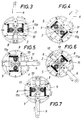
- the crank arm 6 assumes its outermost radial position at the top dead center of the crank movement, in which a lifting force acting on the crank arm occurs as a pure radial component without a tangential component.
- This radial component works over the pair of racks 8 onto the toothed segments 11, the right toothed rack 8, as shown in the drawing, engages with the one toothed section 11a of the right toothed segment 11 when the downward movement begins, while at the same time one of the toothed sections of the left toothed segment comes out of engagement with the left toothed rack (FIG. 3).
- crank arm 6 can be moved downward relative to the crank arm 5, so that the right transmission wheel 10 is rotated via the right toothed segment 11 and, due to the engagement of this transmission wheel with the fixed support wheel 9, a rolling motion and thus a clockwise rotational movement of the crank arm 5 and thus the crankshaft 3 results.
- the left toothed rack and the left toothed segment run without engagement because of the missing toothed section (FIG. 4).
- crank arm 6 reaches its innermost radial position (Fig. 5) after a quarter turn, the toothed segments 11 are rotated to such an extent that the right toothed segment, now the lower one, loses engagement with the associated toothed rack 8 and the left toothed segment, now the upper one, with its corresponding toothed section 11a comes into engagement with the upper rack 8.
- the now starting outward lifting movement of the crank arm 6 therefore leads to a rotation of the upper toothed segment again in a clockwise direction, while the lower toothed segment continues to rotate without engagement, and the upper toothed segment also acts in a rotationally driving manner on the crank arm via the associated transmission wheel 10, which runs on the support wheel 9 5 and the crankshaft 3 (Fig. 6).
- crank arm 6 At bottom dead center, ie after half a turn, the crank arm 6 returns to its outermost radial position and the intermediate gear 7 repeats its sequence of movements as in the crank movement from top dead center, except that the toothed segments 11 now bring the respective other toothed sections 11a to use.
- stroke limit stops and guides are provided, which prevent the risk of loss of engagement on both sides and thus a malfunction.
Landscapes
- Engineering & Computer Science (AREA)
- General Engineering & Computer Science (AREA)
- Mechanical Engineering (AREA)
- Chemical & Material Sciences (AREA)
- Combustion & Propulsion (AREA)
- Transportation (AREA)
- Transmission Devices (AREA)
Claims (3)
- Mécanisme à manivelle (1) avec un arbre-manivelle (3) pouvant tourner librement dans un carter ou bâti quelconque similaire et une manivelle constituée d'une flasque de manivelle (5) montée fixement sur l'arbre-manivelle (3) ainsi que d'un bras de manivelle (6) à déplacement radial logé dans la flasque de manivelle (5). Pour permettre la transformation du mouvement linéaire alternatif du bras de manivelle en un mouvement de rotation de l'arbre-manivelle, une transmission intermédiaire (7) a été prévue avec une crémaillère (8) sur le bras de manivelle (6) disposée dans le sens du mouvement et un engrenage correspondant de roues de transmission et de support (9, 10) attachées respectivement à la flasque de manivelle (5) ou au carter et des segments dentés (11) à action alternative en fonction des mouvements. Ce mécanisme est caractérisé par le fait que le bras de manivelle (6) se place dans la position radiale extrême aux environs du point mort haut du mouvement de manivelle et par la fait que la transmission intermédiaire (7) comprend une paire de crémaillères (8) courtes, fixées sur le bras de manivelle, disposées parallèlement et de façon diamétralement opposée, une roue de support (9) co-axiale avec l'arbre-manivelle fixée sur le carter ainsi qu'une paire de roues de transmission (10) tournant librement dans la flasque de manivelle et des segments dentés (11) co-axiaux attachés fixement aux roues de transmission. La roue de support (9), les roues de transmission (10) et les segments dentés (11) ont des dentures d'un même rayon primitif de référence, leurs axes se situent sur un même plan (12) en ligne normale par rapport à la paire de crémaillères (8); d'une part, la paire de roues de transmission (10) s'engrène en permanence dans la roue de support (9), d'autre part les segments dentés (11) s'engrènent alternativement dans la paire de crémaillères (8).
- Mécanisme de manivelle selon spécification 1, caractérisé par le fait que les parties avec dentures (11a) des segments dentés (11) sont adaptées chacune à un quart de tour et que les segments dentés (11) présentent chacun deux parties avec dentures (11a) diamétralement opposées.
- Mécanisme à manivelle selon spécification 1 ou 2, caractérisé par le fait que les roues de transmission (10) forment chacune une unité de construction avec les segments dentés (11) correspondants.
Applications Claiming Priority (2)
| Application Number | Priority Date | Filing Date | Title |
|---|---|---|---|
| AT113190 | 1990-05-22 | ||
| AT1131/90 | 1990-05-22 |
Publications (2)
| Publication Number | Publication Date |
|---|---|
| EP0462099A1 EP0462099A1 (fr) | 1991-12-18 |
| EP0462099B1 true EP0462099B1 (fr) | 1994-07-13 |
Family
ID=3507269
Family Applications (1)
| Application Number | Title | Priority Date | Filing Date |
|---|---|---|---|
| EP19910890105 Expired - Lifetime EP0462099B1 (fr) | 1990-05-22 | 1991-05-15 | Entraînement à manivelle |
Country Status (2)
| Country | Link |
|---|---|
| EP (1) | EP0462099B1 (fr) |
| DE (1) | DE59102157D1 (fr) |
Families Citing this family (8)
| Publication number | Priority date | Publication date | Assignee | Title |
|---|---|---|---|---|
| JPH0754829A (ja) * | 1993-06-01 | 1995-02-28 | Sokan Shu | クランク装置 |
| KR100386851B1 (ko) * | 1999-12-30 | 2003-06-09 | 강병남 | 자전거의 가변식 페달구동장치 |
| KR100382699B1 (ko) * | 2000-05-03 | 2003-05-09 | 정선국 | 페달구동장치 |
| CN102562998B (zh) * | 2012-02-17 | 2014-07-23 | 安里千 | 一种齿轮-齿块啮合的往复直线运动与旋转运动转换装置 |
| JP6022407B2 (ja) * | 2013-06-04 | 2016-11-09 | 本田技研工業株式会社 | 動力伝達装置 |
| JP6014554B2 (ja) * | 2013-06-05 | 2016-10-25 | 本田技研工業株式会社 | 動力伝達装置 |
| CN103498897B (zh) * | 2013-10-18 | 2016-08-24 | 苏州大学 | 电动双手揉搓仿生装置 |
| CN103498899B (zh) * | 2013-10-18 | 2016-08-24 | 苏州大学 | 电动双手揉搓仿生装置 |
Family Cites Families (2)
| Publication number | Priority date | Publication date | Assignee | Title |
|---|---|---|---|---|
| CH605241A5 (fr) * | 1976-06-28 | 1978-09-29 | Berclaz Rene Louis | |
| US4800768A (en) * | 1987-05-07 | 1989-01-31 | 4N Developments Ltd. | Power transmission apparatus |
-
1991
- 1991-05-15 DE DE59102157T patent/DE59102157D1/de not_active Expired - Fee Related
- 1991-05-15 EP EP19910890105 patent/EP0462099B1/fr not_active Expired - Lifetime
Also Published As
| Publication number | Publication date |
|---|---|
| EP0462099A1 (fr) | 1991-12-18 |
| DE59102157D1 (de) | 1994-08-18 |
Similar Documents
| Publication | Publication Date | Title |
|---|---|---|
| EP0462099B1 (fr) | Entraînement à manivelle | |
| DE60012618T2 (de) | Verstellvorrichtung für den Aussendurchmesser eines Falzzylinders | |
| DE69017106T2 (de) | Zahnradgetriebe mit hohem Wirkungsgrad. | |
| DE2039265A1 (de) | Federtriebwerk,insbesondere fuer Fahrspielzeuge | |
| DE2934874C2 (fr) | ||
| DE1182011B (de) | Getriebe mit mehreren Zahnraedern | |
| DE2202056C3 (de) | Vorrichtung zum Verhindern eines Meßfehlers bei einem Langenmeßgerat | |
| AT398817B (de) | Kurbeltrieb | |
| DE3508767C2 (fr) | ||
| DE520417C (de) | Zahnstangengetriebe zur Umsetzung einer geradlinig hin und her gehenden Bewegung in eine fortlaufende Drehbewegung | |
| DE10021237C2 (de) | Untersetzungsgetriebe mit einem durch Planetenräder gebildeten Wavegenerator | |
| DE10349489B3 (de) | Übertragungs-/Untersetzungsgetriebe für die Rohrbiegungseinheit einer Rohrbiegemaschine | |
| WO1994011651A1 (fr) | Engrenage epicycloïdal a rouleaux avec deux anneaux pourvus d'un profil interne et un element de roulement roulant sur la face externe des anneaux | |
| CH681248A5 (fr) | ||
| DE2619645B1 (de) | Getriebe | |
| DE2357236C2 (de) | Schaltvorrichtung für Wechselgetriebe von Kraftfahrzeugen | |
| DE102007044162A1 (de) | Hubkolbenmaschine | |
| DE2130781B2 (de) | Mehrfach-Antrieb für einen Zahnkranz, mit mehreren Trägern für die Antriebsritzel | |
| DE19923426B4 (de) | Getriebe | |
| DE2159372C3 (de) | Freilaufkupplung | |
| DE2051127A1 (de) | Sitz, insbesondere Kraftfahrzeugsitz | |
| DE20315691U1 (de) | Nabenschaltgetriebe mit Tretkurbelantrieb | |
| CH696038A5 (de) | Lineargetriebe zur Umwandlung einer Drehbewegung in eine Linearbewegung und umgekehrt. | |
| DE399578C (de) | In einem Motorschwungrad untergebrachtes Umlaufraederwechsel- und -wendegetriebe | |
| DE3801597C2 (fr) |
Legal Events
| Date | Code | Title | Description |
|---|---|---|---|
| PUAI | Public reference made under article 153(3) epc to a published international application that has entered the european phase |
Free format text: ORIGINAL CODE: 0009012 |
|
| AK | Designated contracting states |
Kind code of ref document: A1 Designated state(s): BE CH DE DK ES FR GB GR IT LI LU NL SE |
|
| 17P | Request for examination filed |
Effective date: 19920306 |
|
| 17Q | First examination report despatched |
Effective date: 19930930 |
|
| GRAA | (expected) grant |
Free format text: ORIGINAL CODE: 0009210 |
|
| AK | Designated contracting states |
Kind code of ref document: B1 Designated state(s): BE CH DE DK ES FR GB GR IT LI LU NL SE |
|
| PG25 | Lapsed in a contracting state [announced via postgrant information from national office to epo] |
Ref country code: IT Free format text: LAPSE BECAUSE OF FAILURE TO SUBMIT A TRANSLATION OF THE DESCRIPTION OR TO PAY THE FEE WITHIN THE PRE;WARNING: LAPSES OF ITALIAN PATENTS WITH EFFECTIVE DATE BEFORE 2007 MAY HAVE OCCURRED AT ANY TIME BEFORE 2007. THE CORRECT EFFECTIVE DATE MAY BE DIFFERENT FROM THE ONE RECORDED.SCRIBED TIME-LIMIT Effective date: 19940713 Ref country code: BE Effective date: 19940713 Ref country code: GR Free format text: LAPSE BECAUSE OF FAILURE TO SUBMIT A TRANSLATION OF THE DESCRIPTION OR TO PAY THE FEE WITHIN THE PRESCRIBED TIME-LIMIT Effective date: 19940713 Ref country code: NL Effective date: 19940713 Ref country code: GB Effective date: 19940713 Ref country code: FR Effective date: 19940713 Ref country code: DK Effective date: 19940713 Ref country code: ES Free format text: THE PATENT HAS BEEN ANNULLED BY A DECISION OF A NATIONAL AUTHORITY Effective date: 19940713 |
|
| REF | Corresponds to: |
Ref document number: 59102157 Country of ref document: DE Date of ref document: 19940818 |
|
| PG25 | Lapsed in a contracting state [announced via postgrant information from national office to epo] |
Ref country code: SE Effective date: 19941013 |
|
| EN | Fr: translation not filed | ||
| NLV1 | Nl: lapsed or annulled due to failure to fulfill the requirements of art. 29p and 29m of the patents act | ||
| GBV | Gb: ep patent (uk) treated as always having been void in accordance with gb section 77(7)/1977 [no translation filed] |
Effective date: 19941013 |
|
| GBV | Gb: ep patent (uk) treated as always having been void in accordance with gb section 77(7)/1977 [no translation filed] |
Effective date: 19940713 |
|
| GBV | Gb: ep patent (uk) treated as always having been void in accordance with gb section 77(7)/1977 [no translation filed] |
Free format text: DATE CORRECTED TO 940713 |
|
| PLBE | No opposition filed within time limit |
Free format text: ORIGINAL CODE: 0009261 |
|
| STAA | Information on the status of an ep patent application or granted ep patent |
Free format text: STATUS: NO OPPOSITION FILED WITHIN TIME LIMIT |
|
| PG25 | Lapsed in a contracting state [announced via postgrant information from national office to epo] |
Ref country code: LU Free format text: LAPSE BECAUSE OF NON-PAYMENT OF DUE FEES Effective date: 19950531 |
|
| 26N | No opposition filed | ||
| PGFP | Annual fee paid to national office [announced via postgrant information from national office to epo] |
Ref country code: DE Payment date: 20040610 Year of fee payment: 14 |
|
| PG25 | Lapsed in a contracting state [announced via postgrant information from national office to epo] |
Ref country code: DE Free format text: LAPSE BECAUSE OF NON-PAYMENT OF DUE FEES Effective date: 20051201 |
|
| PGFP | Annual fee paid to national office [announced via postgrant information from national office to epo] |
Ref country code: CH Payment date: 20100625 Year of fee payment: 20 |
|
| REG | Reference to a national code |
Ref country code: CH Ref legal event code: PL |