EP0462970B1 - Dispositif de prolongation de la vie d'un element accumulateur electrique - Google Patents
Dispositif de prolongation de la vie d'un element accumulateur electrique Download PDFInfo
- Publication number
- EP0462970B1 EP0462970B1 EP89911690A EP89911690A EP0462970B1 EP 0462970 B1 EP0462970 B1 EP 0462970B1 EP 89911690 A EP89911690 A EP 89911690A EP 89911690 A EP89911690 A EP 89911690A EP 0462970 B1 EP0462970 B1 EP 0462970B1
- Authority
- EP
- European Patent Office
- Prior art keywords
- positive electrode
- polarization
- cell
- electrode
- predetermined level
- Prior art date
- Legal status (The legal status is an assumption and is not a legal conclusion. Google has not performed a legal analysis and makes no representation as to the accuracy of the status listed.)
- Expired - Lifetime
Links
Images
Classifications
-
- H—ELECTRICITY
- H02—GENERATION; CONVERSION OR DISTRIBUTION OF ELECTRIC POWER
- H02J—ELECTRIC POWER NETWORKS; CIRCUIT ARRANGEMENTS OR SYSTEMS FOR SUPPLYING OR DISTRIBUTING ELECTRIC POWER; SYSTEMS FOR STORING ELECTRIC ENERGY
- H02J7/00—Circuit arrangements for charging or discharging batteries or for supplying loads from batteries
- H02J7/90—Regulation of charging or discharging current or voltage
- H02J7/971—Regulation of charging or discharging current or voltage the charge cycle being controlled or terminated in response to non-electric parameters
Definitions
- electrolytic batteries In order to maintain continuity of operation during periods of primary power source failure, many electrical systems, such as the public telephone network, utilize electrolytic batteries as interim sources of operating power. Depending upon the support voltage required, a number of battery cells are arranged in a series-connected string and the string is placed in the system circuit in parallel with the primary rectifier power source. During normal operation of the system, the rectifier source supplies operating power to the system and provides a continual "float" voltage to the cells to maintain the charge that will be needed to support the system in the event of failure of the primary power source.
- the common lead-acid battery cell (PbO2/Pb/H2SO4) widely used in support power supplies has a useful life of a number of years; however, this term is limited by the corrosion occurring, particularly at the positive cell electrode, due to the oxidizing conditions resulting from the repeated application of charging current to the cell. While this effect is exaggerated during periods of recharging after substantial support usage, even the low-level float voltage contributes to significant oxidation of the metallic lead grid at the positive electrode with resulting buildup of oxides that will ultimately cause physical damage to the cell.
- oxidization and corrosion of the plates of electrolytic battery cells is effectively minimized during float charge by the application of a minute additional current to the positive cell electrode to bias the polarization potential of those plates in the electrolyte toward a predetermined level.
- the invention also provides a means for monitoring the polarization potential and metering the appropriate current input to the positive electrode to obtain the desired polarization level.
- the monitoring is effected by means of a low-power, limited current potentiostat-type device which responds to the polarization level by metering to the positive electrode a current of up to about 50 milliamps per kiloamp hour of cell rating depending upon the extent to which the polarization is below the desired optimum.
- the polarization of the cell plates stabilizes within the desired 40-80 millivolt range over the period of a few months and remains at this steady state with little grid metal oxidation.
- the cell may remain in its passivated state for a number of years during which the polarization controller will occasionally introduce the minute adjusting current in order to account for slight polarization variations resulting from changes in cell chemistry and the like.
- reference electrodes have previously been employed in electrical storage cells for various purposes, none have been used to measure the relative state of polarization of the positive electrode in order to determine an appropriate amount of additional current to be applied to the positive electrode during a float charge in order to prevent the oxidation and corrosion of that electrode.
- a smaller negative electrode is included in the charging circuit, but is separated from the charging source by a resistance. The slower charging of the cell with respect to this smaller electrode develops a measureable voltage difference across the resistance and thus provides a means for determining the rate of the recharging process.
- French Patent 2.120.016 describes the use of a dissimilar silver positive electrode in a nickel-cadmium cell to provide a signal when the charge on the cell drops sufficiently low that the potential of the positive nickel electrode falls below that of the silver electrode, thereby causing current to flow in the circuit comprising the silver electrode and signaling the need for cell recharge.
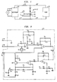
- FIG. 1 A common arrangement for providing continuous direct current power to a load 15, such as a telephone system, is generally shown in FIG. 1.
- a source 11 of alternating current provides the input to a rectifier 13 from which the direct current is furnished to load 15 by means of the circuit comprising conductors 12, 12′, 14′, and 14.
- a series string 17 of a number of electrolytic storage cells Connected between the conductors in parallel with load 15 is a series string 17 of a number of electrolytic storage cells which will ensure the continuity of operating power to the load via conductors 12′, 14′ in the event of failure of the rectifier power system.
- battery string 17 consists of twenty-four nominal 2 volt (2.06 VDC) lead-acid cells to yield a reserve power source of about 47 volts.
- rectifier 13 provides an optimum of about 52 volts which represents a "float", or trickle charge, voltage of about 2.2 volts per cell. This float voltage supports the cell charge by preventing sulfating of the electrodes and promoting oxidation at the surface of the positive electrode. Over time, however, this oxidation not only maintains the desired PbO2 composition of the positive electrode surface, but also leads to a deeper formation of destructive oxide at the metallic lead of the positive electrode grid.
- a preferred range of polarization at the positive cell electrode which provides advantageous results appears to be about 60 ⁇ 20 millivolts with respect to a reference electrode having a chemical composition substantially the same as that of the positive electrode at full charge.
- the polarization of the positive cell electrode may be adjusted to a higher level within the desirable range, thereby reducing the effect of float voltage in promoting deep plate oxidation, by applying a minute additional current of up to about 50 milliamps to this electrode. With increasing polarization this adjusting current may be gradually reduced over time to a point where none is further required when the optimum polarization level has been achieved. Thereafter, the drifting of the polarization toward undesired lower levels may be remedied by occasional application of adjusting current.
- FIG. 1 a monitoring polarization controller system, shown generally in FIG. 1, which comprises a reference electrode 26 and a controller 20, a preferred embodiment of which is more specifically depicted in FIG. 2.
- this system continually monitors the polarization potential between reference electrode 26 and positive battery electrode 22, and meters an appropriate amount of current to the positive electrode to bias the polarization toward the desired level in the noted range of about 60 millivolts.
- An effective current input range stated with reference to the kiloamp-hour rating of the involved battery cell, varies with the relative positive electrode polarization as shown in Table 1.
- each cell of a battery string 17 would have associated with it a reference electrode 26 and a polarization controller 20.
- the controller 20, in each instance, is connected in circuit between the positive cell electrode 22 and the reference electrode 26 which is immersed in the cell electrolyte along with electrode 22 and the negative cell electrode 24.
- the reference electrode 26 has the same PbO2 chemical composition as positive electrode 22, and may be of any convenient shape and size. We have found the rod-like element of a typical tubular battery electrode to be particularly useful, since it may be readily accommodated through the usual battery vent opening.
- a preferred embodiment of a controller 20 according to the present invention is shown in schematic detail in FIG. 2.
- This embodiment utilizes common resistor and capacitor circuit elements selected to exhibit functional values shown in Tables 2 and 3, and includes amplifiers A1-A4, each of which may be one element of a low power quad operational amplifier such as in the LM324 device that is available from National Semiconductor Corporation.
- the circuit further includes general purpose rectifier diodes D1-D3 marketed by Motorola, Inc. as the 1N4004 device, and a general purpose transistor 23, such the 2N2222A product also from Motorola.
- An optional light-emitting diode D4 may be utilized to visually monitor the operation of the controller.
- controller 20 monitors, by means of op-amps A1, A2, the difference in polarization at the positive cell electrode 22 and the reference electrode 26, and utilizing remaining op-amps A3, A4 controls transistor 23 to pass through from +10 VDC source, V1, the appropriate amount of current, as outlined in Table 1.
- Resistor R13 is selected so as to limit to about 250 milliamps the current flow through otherwise unprotected transistor 23. Even with this limitation, however, the polarization controller system will be effective with cells of up to about 5 kAH rating.
- the PbO2 formation at the positive electrode grid surface may be established and maintained in a fine particle state within a few months at normal float current with the result that the positive electrode is effectively passivated by its smooth surface condition to prevent the formation of disruptive oxides at the surface of the lead alloy grid metal.
- the polarization state of the various positive electrodes in the battery string may be monitored by means of the noted optional LED which is illuminated to varying intensity depending upon the level of passivating current input. Persistent illumination of the LED at a particular cell provides a useful diagnostic indication that some malfunction of the cell is preventing optimum charging.
- the reference electrode of a polarization controller system itself requires recharging at four to six month intervals in order to maintain the proper condition of its own PbO2 surface.
- Such reconditioning may readily be effected by simply shorting this reference electrode to the positive cell electrode, or otherwise charging the electrode at about 50mA/kAH, and allowing it to remain on open circuit for about 10 to 15 hours before beginning the control cycle once again.
- This periodic charging of the reference electrode may be accomplished manually, or simple additional circuitry, not shown here, may be included in the controller arrangement to effect such cycling automatically.
- the present invention provides a method and apparatus for maintaining for extended periods of time the effective operating condition of electrolytic battery cells by preventing the destructive oxidation of the structural electrode metal. It is anticipated that other embodiments of the invention will be apparent from the foregoing description to those of ordinary skill in the art, and such embodiments are likewise to be considered within the scope of the invention as set out in the appended claims.
Landscapes
- Engineering & Computer Science (AREA)
- Power Engineering (AREA)
- Secondary Cells (AREA)
- Charge And Discharge Circuits For Batteries Or The Like (AREA)
Abstract
Claims (11)
- Méthode de prolongation de la vie utile d'un élément accumulateur électrique dans un circuit comportant une source (13) de tension de charge d'entretien, dans lequel ledit élément accumulateur comprend une électrode positive (22) et une électrode négative (24) et inclut une électrode de référence (26) en contact avec l'électrolyte dudit élément,
caractérisée en ce que ladite électrode de référence (26) a effectivement la même composition chimique que celle de ladite électrode positive (22) dans l'état de pleine charge, et le potentiel de polarisation de l'électrode positive (22) de l'élément, comparé à ladite électrode de référence (26), est dévié en croissant vers un niveau prédéterminé par l'application d'un courant supplémentaire à ladite électrode positive (22) tant que le potentiel de polarisation est inférieur audit niveau prédéterminé, pour effectivement réduire ainsi au minimum l'oxydation et la corrosion de ladite électrode positive (22) pendant une charge d'entretien. - Méthode selon la revendication 1, dans laquelle ledit élément est un élément de batterie à acide de plomb et ledit niveau prédéterminé est compris environ entre 40 et 80 millivolts.
- Méthode selon la revendication 2, dans laquelle ledit courant supplémentaire appliqué égale jusqu'à 50 milliampères environ par kiloampère-heure du régime de batterie, d'une façon inversement proportionnelle aux potentiels de polarisation au-dessous de 60 millivolts environ.
- Méthode de prolongation de la vie utile d'un élément accumulateur électrique dans un circuit comportant une source (13) de tension de charge d'entretien, dans lequel ledit élément accumulateur comprend une électrode positive (22) et une électrode négative (24) et inclut une électrode de référence (26) en contact avec l'électrolyte dudit élément,
caractérisée en ce quea) ladite électrode de référence (26) a effectivement la même composition chimique superficielle que celle de ladite électrode positive (22) dans l'état de pleine charge;b) la polarisation de ladite électrode positive (22) est mesurée par rapport à ladite électrode de référence (26); etc) ladite polarisation est déviée en croissant vers un niveau prédéterminé par l'application d'un courant supplémentaire à ladite électrode positive (22) tant que ledit potentiel de polarisation est au-dessous dudit niveau prédéterminé, pour effectivement réduire ainsi au minimum l'oxydation et la corrosion de ladite électrode positive (22) pendant une charge d'entretien. - Méthode selon la revendication 4, dans laquelle ledit élément accumulateur est un élément de batterie à acide de plomb et ledit courant supplémentaire appliqué égale jusqu'à environ 50 milliampères par kiloampère-heure du régime de batterie d'une façon inversement proportionnelle aux potentiels de polarisation au-dessous de 60 millivolts environ.
- Méthode selon la revendication 5, dans laquelle ladite tension de charge d'entretien est environ égale à 2,2 volts en courant continu et ledit courant supplémentaire est appliqué à ladite électrode positive (22) effectivement selon le tableau suivant:

- Dispositif de prolongation de la vie utile d'un élément accumulateur électrique dans un circuit comportant une source (13) de tension de charge d'entretien, dans lequel ledit élément accumulateur comprend une électrode positive (22) et une électrode négative (24) et inclut une électrode de référence (26) en contact avec l'électrolyte dudit élément,
caractérisé en ce quea) ladite électrode de référence (26) a effectivement la même composition chimique superficielle que celle de ladite électrode positive (22) dans l'état de pleine charge; etb) ledit dispositif comprend un moyen contrôleur (20) pour mesurer la polarisation de ladite électrode positive (22) par rapport à ladite électrode de référence (26) et pour dévier ladite polarisation en croissant vers un niveau prédéterminé par l'application d'un courant supplémentaire à ladite électrode positive (22) tant que ledit potentiel de polarisation est au-dessous dudit niveau prédéterminé, pour effectivement réduire ainsi au minimum l'oxydation et la corrosion de ladite électrode positive (22) pendant une charge d'entretien. - Dispositif selon la revendication 7, dans lequel ledit élément est un élément de batterie à acide de plomb et ledit niveau prédéterminé est compris environ entre 40 et 80 millivolts.
- Dispositif selon la revendication 8, dans lequel ledit moyen contrôleur (20) comprend:a) un moyen (A₁,A₂) pour comparer le potentiel de polarisation de ladite électrode positive (22) à celui de ladite électrode de référence (26); etb) un moyen (A₃,A₄,V₁,23) réagissant à la différence entre lesdits potentiels pour appliquer à ladite électrode positive (22) un courant supplémentaire égal jusqu'à environ 50 milliampères par kiloampère-heure du régime de batterie d'une façon inversement proportionnelle aux polarisations au-dessous de 60 millivolts environ.
- Dispositif selon la revendication 9, dans lequel ledit moyen pour appliquer un courant supplémentaire comprend:a) une source de courant (V₁)séparée de ladite source de tension de charge d'entretien (13);b) un moyen de déclenchement (A₄,23) pour mesurer le courant provenant de ladite source séparée (V₁) qui est appliqué à ladite électrode positive (22); etc) un moyen (A₁-A₃) réagissant à la différence entre lesdits potentiels pour commander ledit moyen de déclenchement (A₄,23).
- Dispositif selon la revendication 10, dans lequel ladite tension de charge d'entretien est environ égale à 2,2 volts en courant continu et ledit moyen de déclenchement (A₄,23) est agencé pour réaliser l'application du courant à ladite électrode positive (22) effectivement selon le tableau suivant:

Applications Claiming Priority (2)
| Application Number | Priority Date | Filing Date | Title |
|---|---|---|---|
| US07/322,730 US4935688A (en) | 1989-03-13 | 1989-03-13 | Electrical storage cell life extender |
| US322730 | 1989-03-13 |
Publications (2)
| Publication Number | Publication Date |
|---|---|
| EP0462970A1 EP0462970A1 (fr) | 1992-01-02 |
| EP0462970B1 true EP0462970B1 (fr) | 1993-04-07 |
Family
ID=23256151
Family Applications (1)
| Application Number | Title | Priority Date | Filing Date |
|---|---|---|---|
| EP89911690A Expired - Lifetime EP0462970B1 (fr) | 1989-03-13 | 1989-09-26 | Dispositif de prolongation de la vie d'un element accumulateur electrique |
Country Status (5)
| Country | Link |
|---|---|
| US (1) | US4935688A (fr) |
| EP (1) | EP0462970B1 (fr) |
| JP (1) | JP2536788B2 (fr) |
| CA (1) | CA1319952C (fr) |
| WO (1) | WO1990010969A1 (fr) |
Families Citing this family (12)
| Publication number | Priority date | Publication date | Assignee | Title |
|---|---|---|---|---|
| TW226472B (fr) | 1992-06-01 | 1994-07-11 | Gen Electric | |
| US5731684A (en) * | 1993-03-17 | 1998-03-24 | Uli Rotermund | Method and apparatus for regenerating primary cells |
| US5543701A (en) * | 1993-11-09 | 1996-08-06 | Bell Communications Research, Inc. | Electrical storage cell polarization controller |
| US5463304A (en) * | 1993-11-22 | 1995-10-31 | Winters; Thomas L. | Life extending circuit for storage batteries |
| US5750288A (en) * | 1995-10-03 | 1998-05-12 | Rayovac Corporation | Modified lithium nickel oxide compounds for electrochemical cathodes and cells |
| US5864223A (en) * | 1996-11-05 | 1999-01-26 | Meyer; Dennis R. | Battery life extender apparatus |
| US5969507A (en) * | 1998-04-06 | 1999-10-19 | Meyer; Dennis R. | Battery life extender apparatus |
| US6346817B1 (en) | 2000-04-27 | 2002-02-12 | Multitel Inc. | Float current measuring probe and method |
| CN1879251B (zh) | 2003-07-02 | 2011-10-12 | 伊顿动力品质有限公司 | 电池浮充管理 |
| US9893369B2 (en) | 2013-07-30 | 2018-02-13 | Elwha Llc | Managed access electrochemical energy generation system |
| US9343783B2 (en) * | 2013-07-30 | 2016-05-17 | Elwha Llc | Electrochemical energy generation system having individually controllable cells |
| US9484601B2 (en) * | 2013-07-30 | 2016-11-01 | Elwha Llc | Load-managed electrochemical energy generation system |
Family Cites Families (14)
| Publication number | Priority date | Publication date | Assignee | Title |
|---|---|---|---|---|
| US2355351A (en) * | 1943-02-05 | 1944-08-08 | Gen Railway Signal Co | Primary battery depolarizing system |
| DE1496344B2 (de) * | 1965-12-10 | 1970-11-19 | Varta AG, 6OOO Frankfurt | Akkumulatorenzelle, die neben positiven und negativen Hauptelektroden eine Steuerelektrode enthält |
| US3505584A (en) * | 1966-05-11 | 1970-04-07 | Us Navy | Charge current controller for sealed electro-chemical cells with control electrodes |
| DE1763333A1 (de) * | 1968-05-08 | 1971-05-19 | Philips Patentverwaltung | Schaltungsanordnung zur Endpunktsanzeige des Lade- oder Entladevorganges einer Sekundaerbatterie |
| DE2100011C3 (de) * | 1971-01-02 | 1974-01-17 | Varta Batterie Ag, 3000 Hannover | Verfahren und Vorrichtung zur Messung und Anzeige des Ladezustandes von Nickel-Cadmium-Akkumulatoren |
| US4039920A (en) * | 1973-10-31 | 1977-08-02 | Westinghouse Air Brake Company | Cycling type of electronic battery charger |
| US3911349A (en) * | 1974-11-07 | 1975-10-07 | Esb Inc | Battery charger |
| US4358892A (en) * | 1977-11-10 | 1982-11-16 | The International Nickel Company, Inc. | Method of producing battery and electrolytic cell electrodes |
| US4282474A (en) * | 1979-11-19 | 1981-08-04 | Laura May Usher | Life-prolonging device for hearing-aid batteries |
| US4358895A (en) * | 1981-06-26 | 1982-11-16 | Colt Industries Operating Corp. | Continuous contact gage for strip rolling process having floating mechanism |
| SE451924B (sv) * | 1982-10-12 | 1987-11-02 | Ericsson Telefon Ab L M | Regulator for reglering av en laddningsstrom till en enskild cell i ett batteri av celler |
| US4621225A (en) * | 1984-02-06 | 1986-11-04 | Pittway Corporation | Passive transformerless battery charging circuit |
| US4728877A (en) * | 1986-06-10 | 1988-03-01 | Adaptive Instruments Corp. | Method and apparatus for improving electrochemical processes |
| US4740739A (en) * | 1987-02-10 | 1988-04-26 | Premier Engineered Products Corporation | Battery charging apparatus and method |
-
1989
- 1989-03-13 US US07/322,730 patent/US4935688A/en not_active Expired - Fee Related
- 1989-09-01 CA CA000610122A patent/CA1319952C/fr not_active Expired - Fee Related
- 1989-09-26 JP JP1510878A patent/JP2536788B2/ja not_active Expired - Lifetime
- 1989-09-26 WO PCT/US1989/004196 patent/WO1990010969A1/fr not_active Ceased
- 1989-09-26 EP EP89911690A patent/EP0462970B1/fr not_active Expired - Lifetime
Also Published As
| Publication number | Publication date |
|---|---|
| JP2536788B2 (ja) | 1996-09-18 |
| EP0462970A1 (fr) | 1992-01-02 |
| CA1319952C (fr) | 1993-07-06 |
| WO1990010969A1 (fr) | 1990-09-20 |
| US4935688A (en) | 1990-06-19 |
| JPH04507338A (ja) | 1992-12-17 |
Similar Documents
| Publication | Publication Date | Title |
|---|---|---|
| EP0462970B1 (fr) | Dispositif de prolongation de la vie d'un element accumulateur electrique | |
| US6040685A (en) | Energy transfer and equalization in rechargeable lithium batteries | |
| CA1161497A (fr) | Chargeur d'accumulateurs | |
| US4052656A (en) | Battery charging system | |
| US4736150A (en) | Method of increasing the useful life of rechargeable lithium batteries | |
| US4194146A (en) | Device for controlling the charging and discharging of a storage battery | |
| US6476583B2 (en) | Automatic battery charging system for a battery back-up DC power supply | |
| US4698578A (en) | Circuit for supplying energy from a battery to an energy-using device | |
| US4086525A (en) | Circuit for preventing overdischarge of a battery | |
| US4467265A (en) | Battery charger | |
| US20050156577A1 (en) | Method for charge control for extending Li-Ion battery life | |
| US4386308A (en) | Hysteresis type battery charger having output short circuit protection | |
| WO1998058271A1 (fr) | Appareil d'exploitation d'un accumulateur de reserve pour charger ou tester des elements individuels dans une chaine d'elements d'accumulateur | |
| US4728877A (en) | Method and apparatus for improving electrochemical processes | |
| US4342954A (en) | Battery conditioning methods and apparatus | |
| CA2174845C (fr) | Controleur de polarisation d'element d'accumulateur | |
| US4290002A (en) | Method and apparatus for controlling battery recharging | |
| US5631535A (en) | Regulator for charging a rechargeable storage device from a photovoltaic cell | |
| EP0090035A1 (fr) | Circuit regulateur de tension et limiteur de la dissipation d'une batterie | |
| US4349614A (en) | Platinum third electrode to improve float polarization of standby batteries | |
| US3538415A (en) | Fast battery charger | |
| US4039920A (en) | Cycling type of electronic battery charger | |
| JPS61206179A (ja) | リチウム二次電池の直列接続回路 | |
| US3421068A (en) | Trickle charge voltage stabilization nickel-cadmium battery | |
| US5831416A (en) | Apparatus and method for charging batteries |
Legal Events
| Date | Code | Title | Description |
|---|---|---|---|
| PUAI | Public reference made under article 153(3) epc to a published international application that has entered the european phase |
Free format text: ORIGINAL CODE: 0009012 |
|
| 17P | Request for examination filed |
Effective date: 19910829 |
|
| AK | Designated contracting states |
Kind code of ref document: A1 Designated state(s): DE GB IT SE |
|
| 17Q | First examination report despatched |
Effective date: 19920622 |
|
| GRAA | (expected) grant |
Free format text: ORIGINAL CODE: 0009210 |
|
| AK | Designated contracting states |
Kind code of ref document: B1 Designated state(s): DE GB IT SE |
|
| REF | Corresponds to: |
Ref document number: 68905927 Country of ref document: DE Date of ref document: 19930513 |
|
| ITF | It: translation for a ep patent filed | ||
| PLBE | No opposition filed within time limit |
Free format text: ORIGINAL CODE: 0009261 |
|
| STAA | Information on the status of an ep patent application or granted ep patent |
Free format text: STATUS: NO OPPOSITION FILED WITHIN TIME LIMIT |
|
| 26N | No opposition filed | ||
| EAL | Se: european patent in force in sweden |
Ref document number: 89911690.9 |
|
| PGFP | Annual fee paid to national office [announced via postgrant information from national office to epo] |
Ref country code: SE Payment date: 19980820 Year of fee payment: 10 |
|
| PGFP | Annual fee paid to national office [announced via postgrant information from national office to epo] |
Ref country code: GB Payment date: 19980826 Year of fee payment: 10 Ref country code: DE Payment date: 19980826 Year of fee payment: 10 |
|
| PG25 | Lapsed in a contracting state [announced via postgrant information from national office to epo] |
Ref country code: GB Free format text: LAPSE BECAUSE OF NON-PAYMENT OF DUE FEES Effective date: 19990926 |
|
| PG25 | Lapsed in a contracting state [announced via postgrant information from national office to epo] |
Ref country code: SE Free format text: THE PATENT HAS BEEN ANNULLED BY A DECISION OF A NATIONAL AUTHORITY Effective date: 19990929 |
|
| EUG | Se: european patent has lapsed |
Ref document number: 89911690.9 |
|
| GBPC | Gb: european patent ceased through non-payment of renewal fee |
Effective date: 19990926 |
|
| PG25 | Lapsed in a contracting state [announced via postgrant information from national office to epo] |
Ref country code: DE Free format text: LAPSE BECAUSE OF NON-PAYMENT OF DUE FEES Effective date: 20000701 |
|
| PG25 | Lapsed in a contracting state [announced via postgrant information from national office to epo] |
Ref country code: IT Free format text: LAPSE BECAUSE OF NON-PAYMENT OF DUE FEES;WARNING: LAPSES OF ITALIAN PATENTS WITH EFFECTIVE DATE BEFORE 2007 MAY HAVE OCCURRED AT ANY TIME BEFORE 2007. THE CORRECT EFFECTIVE DATE MAY BE DIFFERENT FROM THE ONE RECORDED. Effective date: 20050926 |
|
| REG | Reference to a national code |
Ref country code: GB Ref legal event code: 732E Free format text: REGISTERED BETWEEN 20090903 AND 20090909 |