EP0463759A2 - Production of thermoplastics foams - Google Patents
Production of thermoplastics foams Download PDFInfo
- Publication number
- EP0463759A2 EP0463759A2 EP91305208A EP91305208A EP0463759A2 EP 0463759 A2 EP0463759 A2 EP 0463759A2 EP 91305208 A EP91305208 A EP 91305208A EP 91305208 A EP91305208 A EP 91305208A EP 0463759 A2 EP0463759 A2 EP 0463759A2
- Authority
- EP
- European Patent Office
- Prior art keywords
- mixer
- rotor
- stator
- cavities
- nitrogen gas
- Prior art date
- Legal status (The legal status is an assumption and is not a legal conclusion. Google has not performed a legal analysis and makes no representation as to the accuracy of the status listed.)
- Withdrawn
Links
Images


Classifications
-
- B—PERFORMING OPERATIONS; TRANSPORTING
- B29—WORKING OF PLASTICS; WORKING OF SUBSTANCES IN A PLASTIC STATE IN GENERAL
- B29C—SHAPING OR JOINING OF PLASTICS; SHAPING OF MATERIAL IN A PLASTIC STATE, NOT OTHERWISE PROVIDED FOR; AFTER-TREATMENT OF THE SHAPED PRODUCTS, e.g. REPAIRING
- B29C44/00—Shaping by internal pressure generated in the material, e.g. swelling or foaming ; Producing porous or cellular expanded plastics articles
- B29C44/34—Auxiliary operations
- B29C44/3442—Mixing, kneading or conveying the foamable material
- B29C44/3446—Feeding the blowing agent
-
- B—PERFORMING OPERATIONS; TRANSPORTING
- B29—WORKING OF PLASTICS; WORKING OF SUBSTANCES IN A PLASTIC STATE IN GENERAL
- B29C—SHAPING OR JOINING OF PLASTICS; SHAPING OF MATERIAL IN A PLASTIC STATE, NOT OTHERWISE PROVIDED FOR; AFTER-TREATMENT OF THE SHAPED PRODUCTS, e.g. REPAIRING
- B29C44/00—Shaping by internal pressure generated in the material, e.g. swelling or foaming ; Producing porous or cellular expanded plastics articles
- B29C44/34—Auxiliary operations
- B29C44/3402—Details of processes or apparatus for reducing environmental damage or for working-up compositions comprising inert blowing agents or biodegradable components
-
- B—PERFORMING OPERATIONS; TRANSPORTING
- B29—WORKING OF PLASTICS; WORKING OF SUBSTANCES IN A PLASTIC STATE IN GENERAL
- B29C—SHAPING OR JOINING OF PLASTICS; SHAPING OF MATERIAL IN A PLASTIC STATE, NOT OTHERWISE PROVIDED FOR; AFTER-TREATMENT OF THE SHAPED PRODUCTS, e.g. REPAIRING
- B29C48/00—Extrusion moulding, i.e. expressing the moulding material through a die or nozzle which imparts the desired form; Apparatus therefor
- B29C48/25—Component parts, details or accessories; Auxiliary operations
- B29C48/285—Feeding the extrusion material to the extruder
- B29C48/29—Feeding the extrusion material to the extruder in liquid form
-
- B—PERFORMING OPERATIONS; TRANSPORTING
- B29—WORKING OF PLASTICS; WORKING OF SUBSTANCES IN A PLASTIC STATE IN GENERAL
- B29C—SHAPING OR JOINING OF PLASTICS; SHAPING OF MATERIAL IN A PLASTIC STATE, NOT OTHERWISE PROVIDED FOR; AFTER-TREATMENT OF THE SHAPED PRODUCTS, e.g. REPAIRING
- B29C48/00—Extrusion moulding, i.e. expressing the moulding material through a die or nozzle which imparts the desired form; Apparatus therefor
- B29C48/25—Component parts, details or accessories; Auxiliary operations
- B29C48/285—Feeding the extrusion material to the extruder
- B29C48/295—Feeding the extrusion material to the extruder in gaseous form
-
- B—PERFORMING OPERATIONS; TRANSPORTING
- B29—WORKING OF PLASTICS; WORKING OF SUBSTANCES IN A PLASTIC STATE IN GENERAL
- B29C—SHAPING OR JOINING OF PLASTICS; SHAPING OF MATERIAL IN A PLASTIC STATE, NOT OTHERWISE PROVIDED FOR; AFTER-TREATMENT OF THE SHAPED PRODUCTS, e.g. REPAIRING
- B29C48/00—Extrusion moulding, i.e. expressing the moulding material through a die or nozzle which imparts the desired form; Apparatus therefor
- B29C48/25—Component parts, details or accessories; Auxiliary operations
- B29C48/36—Means for plasticising or homogenising the moulding material or forcing it through the nozzle or die
- B29C48/365—Means for plasticising or homogenising the moulding material or forcing it through the nozzle or die using pumps, e.g. piston pumps
- B29C48/37—Gear pumps
-
- B—PERFORMING OPERATIONS; TRANSPORTING
- B29—WORKING OF PLASTICS; WORKING OF SUBSTANCES IN A PLASTIC STATE IN GENERAL
- B29C—SHAPING OR JOINING OF PLASTICS; SHAPING OF MATERIAL IN A PLASTIC STATE, NOT OTHERWISE PROVIDED FOR; AFTER-TREATMENT OF THE SHAPED PRODUCTS, e.g. REPAIRING
- B29C48/00—Extrusion moulding, i.e. expressing the moulding material through a die or nozzle which imparts the desired form; Apparatus therefor
- B29C48/25—Component parts, details or accessories; Auxiliary operations
- B29C48/36—Means for plasticising or homogenising the moulding material or forcing it through the nozzle or die
- B29C48/375—Plasticisers, homogenisers or feeders comprising two or more stages
- B29C48/385—Plasticisers, homogenisers or feeders comprising two or more stages using two or more serially arranged screws in separate barrels
-
- B—PERFORMING OPERATIONS; TRANSPORTING
- B29—WORKING OF PLASTICS; WORKING OF SUBSTANCES IN A PLASTIC STATE IN GENERAL
- B29C—SHAPING OR JOINING OF PLASTICS; SHAPING OF MATERIAL IN A PLASTIC STATE, NOT OTHERWISE PROVIDED FOR; AFTER-TREATMENT OF THE SHAPED PRODUCTS, e.g. REPAIRING
- B29C48/00—Extrusion moulding, i.e. expressing the moulding material through a die or nozzle which imparts the desired form; Apparatus therefor
- B29C48/25—Component parts, details or accessories; Auxiliary operations
- B29C48/36—Means for plasticising or homogenising the moulding material or forcing it through the nozzle or die
- B29C48/395—Means for plasticising or homogenising the moulding material or forcing it through the nozzle or die using screws surrounded by a cooperating barrel, e.g. single screw extruders
- B29C48/40—Means for plasticising or homogenising the moulding material or forcing it through the nozzle or die using screws surrounded by a cooperating barrel, e.g. single screw extruders using two or more parallel screws or at least two parallel non-intermeshing screws, e.g. twin screw extruders
-
- B—PERFORMING OPERATIONS; TRANSPORTING
- B29—WORKING OF PLASTICS; WORKING OF SUBSTANCES IN A PLASTIC STATE IN GENERAL
- B29C—SHAPING OR JOINING OF PLASTICS; SHAPING OF MATERIAL IN A PLASTIC STATE, NOT OTHERWISE PROVIDED FOR; AFTER-TREATMENT OF THE SHAPED PRODUCTS, e.g. REPAIRING
- B29C48/00—Extrusion moulding, i.e. expressing the moulding material through a die or nozzle which imparts the desired form; Apparatus therefor
- B29C48/25—Component parts, details or accessories; Auxiliary operations
- B29C48/36—Means for plasticising or homogenising the moulding material or forcing it through the nozzle or die
- B29C48/465—Means for plasticising or homogenising the moulding material or forcing it through the nozzle or die using rollers
- B29C48/467—Means for plasticising or homogenising the moulding material or forcing it through the nozzle or die using rollers using single rollers, e.g. provided with protrusions, closely surrounded by a housing with movement of the material in the axial direction
- B29C48/468—Cavity transfer mixing devices, i.e. a roller and surrounding barrel both provided with cavities; Barrels and rollers therefor
-
- B—PERFORMING OPERATIONS; TRANSPORTING
- B29—WORKING OF PLASTICS; WORKING OF SUBSTANCES IN A PLASTIC STATE IN GENERAL
- B29C—SHAPING OR JOINING OF PLASTICS; SHAPING OF MATERIAL IN A PLASTIC STATE, NOT OTHERWISE PROVIDED FOR; AFTER-TREATMENT OF THE SHAPED PRODUCTS, e.g. REPAIRING
- B29C48/00—Extrusion moulding, i.e. expressing the moulding material through a die or nozzle which imparts the desired form; Apparatus therefor
- B29C48/25—Component parts, details or accessories; Auxiliary operations
- B29C48/36—Means for plasticising or homogenising the moulding material or forcing it through the nozzle or die
- B29C48/47—Means for plasticising or homogenising the moulding material or forcing it through the nozzle or die using discs, e.g. plasticising the moulding material by passing it between a fixed and a rotating disc that are coaxially arranged
-
- B—PERFORMING OPERATIONS; TRANSPORTING
- B29—WORKING OF PLASTICS; WORKING OF SUBSTANCES IN A PLASTIC STATE IN GENERAL
- B29C—SHAPING OR JOINING OF PLASTICS; SHAPING OF MATERIAL IN A PLASTIC STATE, NOT OTHERWISE PROVIDED FOR; AFTER-TREATMENT OF THE SHAPED PRODUCTS, e.g. REPAIRING
- B29C48/00—Extrusion moulding, i.e. expressing the moulding material through a die or nozzle which imparts the desired form; Apparatus therefor
- B29C48/03—Extrusion moulding, i.e. expressing the moulding material through a die or nozzle which imparts the desired form; Apparatus therefor characterised by the shape of the extruded material at extrusion
- B29C48/07—Flat, e.g. panels
-
- B—PERFORMING OPERATIONS; TRANSPORTING
- B29—WORKING OF PLASTICS; WORKING OF SUBSTANCES IN A PLASTIC STATE IN GENERAL
- B29K—INDEXING SCHEME ASSOCIATED WITH SUBCLASSES B29B, B29C OR B29D, RELATING TO MOULDING MATERIALS OR TO MATERIALS FOR MOULDS, REINFORCEMENTS, FILLERS OR PREFORMED PARTS, e.g. INSERTS
- B29K2105/00—Condition, form or state of moulded material or of the material to be shaped
- B29K2105/0005—Condition, form or state of moulded material or of the material to be shaped containing compounding ingredients
Definitions
- the present invention is concerned with the commercial production of thermoplastics foams, such as polyethylene and polystyrene.
- thermoplastics foams The conventional techniques for the production of thermoplastics foams involves the use of liquid physical foaming agents or solid powder chemical foaming agents which are readily mixed into the polymer by conventional extruder screws.
- a gas such as nitrogen
- Conventional extruder screws do not provide sufficient mixing for this purpose.
- a known alternative is to incorporate nitrogen gas by diffusion into crosslinked polyolefines using very high pressure autoclaves, but this has the disadvantage of being limited to the manufacture of foam blocks by a batch process from which products have to be cut.
- An object of the present invention is to overcome the abovedescribed problems of using nitrogen inherent in the production of thermoplastics foams.
- a method for the production of foamed thermoplastics using nitrogen gas as the foaming agent wherein the nitrogen gas is mixed with a polymer melt in a mixing apparatus of the type comprising a hollow cylindrical stator, (not necessarily static), and a cylindrical rotor journalled for rotation within the stator, the facing cylindrical surfaces of the rotor and stator carrying respective pluralities of circumferentially extending rows of cavities, between which material to be mixed is passed in travelling through the mixer.
- the mixer is a cavity transfer mixer of the type described and claimed in our prior European Patent No. 48590, i.e. one in which the cavities are disposed with (a) the cavities in adjacent rows on the stator circumferentially offset, (b) the cavities in adjacent rows on the rotor circumferentially offset, and (c) the rows of cavities on the stator and rotor axially offset.
- the invention also provides an apparatus for the production of foamed thermoplastics using nitrogen gas as the foaming agent, the apparatus comprising a mixer of the abovedescribed type (preferably a Cavity Transfer Mixer of the type claimed in our prior European Patent No. 48590), an extruder for supplying polymer melt to the input end of the mixer, and a gas inlet disposed at or adjacent the inlet end of the mixer for enabling nitrogen gas to be introduced thereto.
- a mixer of the abovedescribed type preferably a Cavity Transfer Mixer of the type claimed in our prior European Patent No. 48590
- an extruder for supplying polymer melt to the input end of the mixer
- a gas inlet disposed at or adjacent the inlet end of the mixer for enabling nitrogen gas to be introduced thereto.
- a cooling means at the outlet end of the mixer for cooling the polymer/nitrogen mixture prior to this being passed through a die.
- the extruder may have a screw which is attached directly to the rotor of the mixer so that the rotor and screw rotate together.
- the rotor of the mixer can be driven by a separate drive means so as to enable it to be driven at a faster or lower speed than the extruder screw.
- the use of nitrogen as a blowing agent for extruded foamed thermoplastics is made available, thereby eliminating the current use of CFCs and also providing a superior replacement than pentanes and their like.
- the basic process to be performed involves melting a suitable polymer, introducing nitrogen gas into the polymer melt, and allowing expansion to foam the polymer.
- the nitrogen which is obtained from the air by distillation returns to the air during foaming to complete the cycle.
- the problem is how to obtain sufficient, uniform mixing of the nitrogen with the polymer melt.
- a mixer of the type comprising a hollow cylindrical (not necessarily static) stator, a cylindrical rotor journalled for rotation within the stator, the facing cylindrical surfaces of the rotor and stator carrying respective pluralities of circumferentially extending rows of cavities between which material to be mixed is passed in travelling through the mixer.
- the mixer is a so-called Cavity Transfer Mixer, of the type disclosed and claimed in our earlier European Patent No. 48590, to which reference is hereby directed for full technical details.
- Such a cavity transfer mixer comprises a hollow cylindrical stator, a cylindrical rotor journalled for rotation within the stator, the facing cylindrical surfaces of the rotor and stator carrying respective pluralities of parallel, circumferentially extending rows of cavities, and the cavities being disposed with:
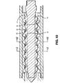
- the mixer illustrated in Figs. 10 to 13 includes a rotor 10 which is rotatably mounted within a basically cylindrical bore 12 in a stator 14.
- the right-hand end of the rotor 10, as viewed in Fig. 10, is adapted to be keyed to the output end of a screw conveyor (not shown) and the left-hand end of the stator 14 is adapted to be attached to an extrusion die (not shown) whereby material being processed, e.g. polymer is forced between the rotor and stator in passing from the screw conveyor to the extrusion die.
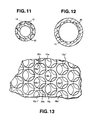
- the facing surfaces 16 and 12 on the rotor and stator are formed with respective pluralities of hemispherical cavities 18, 20.
- the cavities 18 on the rotor are disposed in a plurality of circumferentially extending rows.
- 12 snd 13 adjacent rows on the rotor are circumferentially displaced such that the centre of each cavity in a given row lies midway; between the centres of the two nearest cavities in the or each adjacent row. This can best be seen from the developed view of Fig.
- the circles 18a, 18b, 18c represent the cavities in one row on the rotor and the circles 18a′, 18b′, 18c′ and 18a′′, 18b′′, 18c′′ represent the cavities in the adjacent rotor rows.
- the circle identified as 18b is offset in the circumferential direction from the adjacent circles 18a′, 18b′, 18a′′ and 18b′′ by half the distance between the centres of any two adjacent cavities in a row, e.g. between the centres of the cavities 18a and 18b.
- the cavities 20 on the stator are disposed in a plurality of circumferentially extending rows, adjacent rows on the stator again being circumferentially displaced such that the cavities in a given row are offset by half the distance between the centres of any two adjacent cavities in a row.
- the relative axial positions of the rows on the rotor and stator are also offset as best seen in Fig. 13, such that the circumferential line joining the centre of any given row of cavities on the stator lies in the same axial position as a circumferential line positioned midway between the two circumferential lines joining the centres of the cavities in the two adjacent rotor rows.
- Fig. 13 the circumferential line joining the centre of any given row of cavities on the stator lies in the same axial position as a circumferential line positioned midway between the two circumferential lines joining the centres of the cavities in the two adjacent rotor rows.
- the centres of the stator cavities 20a, 20b lie on a circumferential line positioned midway between the circumferential line joining the centres of rotor cavities 18a′′, 18b′′, 18c′′ and the circumferential line joining the centres of the rotor cavities 18a, 18b, 18c.
- a cavity transfer mixer of the above described type performs a mixing process in which two or more components are mixed by transfer between rows of the cavities within both the hollow cylindrical stator 14 and the cylindrical rotor 10 the mixing process being obtained by repeated cutting and turning operations on the mixture at the transfers between cavities on the opposed faces of the stator and rotor and by dividing the mixture flow between pairs of adjacent cavities on the same rotor or stator face by means of a respective overlapping cavity on the opposite stator or rotor face.
- the polymer melt is passed through such a cavity transfer mixer, together with nitrogen gas, or a mixture of nitrogen and one or more other inert gases.
- a cavity transfer mixer 30 of the type defined hereinbefore is connected to the output end of a plastics extruder 32, to which the polymer is introduced by a hopper feeder 34.
- the extruder is driven by a motor 36, usually an electric motor.
- the rotor of the cavity transfer mixer 30 is attached to the screw of the extruder and the stator to the extruder barrel such that the rotor rotates with the extruder screw.
- molten thermoplastic is introduced to the input (right-hand as viewed in Fig.2) end of the cavity transfer mixer 30.
- Nitrogen gas can also be introduced into or adjacent the input end of the cavity transfer mixer 30, by way of an inlet gas pipe 38.
- the cavity transfer mixer 30 In being subjected to the special mixing action obtained by the cavity transfer mixer 30 it is found that uniform mixing of the nitrogen with the polymer occurs.
- the resulting polymer/nitrogen mix is cooled by a cooling jacket arrangement 40 and extruded via a die 42 to produce a mass of extruded foam 44, shaped into a product which may be a sheet, film, tube or other profile.
- a cooling jacket arrangement 40 and extruded via a die 42 to produce a mass of extruded foam 44, shaped into a product which may be a sheet, film, tube or other profile.
- the extruder 32 may be a general purpose helical screw-type extruder or one designed for high output rates, e.g. by using grooved feeds or special mixing screws.
- This first embodiment is suitable for forms of medium density down to about 100 kg/m3.
- the addition of cooling e.g. by using a cooled static mixer or a cooled screw extension to the cavity transfer mixer rotor, increases the viscosity of the polymer melt so that on expansion gas is less likely to diffuse out and bubbles are less inclined to coalesce or burst, so that low density foams can be achieved.
- the dissolved nitrogen plasticises the melt so that a processable viscosity exists. As the nitrogen comes out of solution at a comparatively low temperature, the viscosity will rise rapidly as the melt leaves the die, thereby giving an improved foam.
- the higher rotor speed enables higher nitrogen levels to be uniformly mixed, whilst the gear pump generates the higher pressures necessary for the solution of higher nitrogen levels. As a result, lower density foams can be produced.
- cooling water for the mixer 30 and/or cooler 40 may be introduced to internal cooling cavities in the mixer 30 and/or cooler 40 by way of a rotary union 49 (Fig. 3).
- Fig. 4 illustrates one possible system for the supply of nitrogen gas to the mixer 30.
- Nitrogen gas is stored in a gas cylinder 50, the gas pressure being boosted in an air-driven gas boost compressor 52 of the types currently available which are capable of pressures up to 700 bar.
- the pressurised gas is stored in a reservoir 54 and can be supplied, via a suitable valve 56 and meter 58 to a gas injector 60.
- the gas injector can comprise a simple non-return or check valve, such as a poppet valve 62 (Fig. 7a) or ball check valve 64 (Fig. 7b).
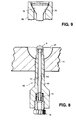
- a typical poppet valve arrangement 80 is shown in Figs. 8 and 9.
- This comprises an elongate injector body 66 having a longitudinal through-bore 68. Longitudinally displaceable within the bore 68, against the biassing effect of a coil spring 70, is an elongate valve stem 72 having a frusto-conical valve body 74 at one end which cooperates with a correspondingly frusto-conical valve seat 76 (see Fig. 9). Gas is supplied to the injector via a standard connector 78.
- Fig. 8 shows the outlet end of the gas injector 80 emerging within one of the hemi-spherical cavities 20 in the stator 14 of a cavity transfer mixer of the type shown in Figs. 10 to 13 (see also Fig. 5).
- This arrangement is found to be suitable for larger machines, for example 90m.m. and above.
- a rotor cavity 18a which, as illustrated diagrammatically in Figure 6, can be of the type which is extended in a direction along the axis of the mixer.
- the provision of extended rotor cavities at the upstream end of the mixer is often made to improve initial introduction of the mix into the mixer.
Landscapes
- Engineering & Computer Science (AREA)
- Mechanical Engineering (AREA)
- Health & Medical Sciences (AREA)
- Life Sciences & Earth Sciences (AREA)
- Biodiversity & Conservation Biology (AREA)
- Environmental & Geological Engineering (AREA)
- Environmental Sciences (AREA)
- Toxicology (AREA)
- Extrusion Moulding Of Plastics Or The Like (AREA)
- Manufacture Of Porous Articles, And Recovery And Treatment Of Waste Products (AREA)
- Molding Of Porous Articles (AREA)
- Processing And Handling Of Plastics And Other Materials For Molding In General (AREA)
Abstract
A method and apparatus for the production of foamed thermoplastics using nitrogen gas as the foaming agent, wherein the nitrogen gas is mixed with a polymer melt in a mixing apparatus of the type comprising a hollow cylindrical stator (14), (not necessarily static), and a cylindrical rotor (10) journalled for rotation within the stator (14), the facing cylindrical-surfaces of the rotor and stator carrying respective pluralities of circumferentially extending rows of cavities (18, 20); between which material to be mixed is passed in travelling through the mixer. Nitrogen gas is introduced into the polymer melt via a gas injector disposed at the upstream end of the mixer.
Description
- The present invention is concerned with the commercial production of thermoplastics foams, such as polyethylene and polystyrene.
- Large volumes of extruded foamed plastics sheet, board and sleeves (used mainly for packaging and insulation) are foamed by the incorporation of either CFCs or aliphatic hydrocarbons. It is acknowledged that there is a need to use an alternative to CFCs in order to protect the environment. There is also a need to use a substitute which is non-flammable and creates no hazards in manufacture, storage and application. Pentane and similar hydrocarbons currently used as substitutes for CFCs create severe fire hazards and environmental pollution whilst chemical foaming agents, such as azodicarbonamide can spontaneously ignite during storage and liberate toxic byproducts during the foaming process.
- It has previously been proposed to try to use nitrogen as the blowing agent in the production of thermoplastics foams but this has so far been insufficiently successful for commercial use due to the problems of uniformly mixing the nitrogen into the polymer melt.
- The conventional techniques for the production of thermoplastics foams involves the use of liquid physical foaming agents or solid powder chemical foaming agents which are readily mixed into the polymer by conventional extruder screws. When a gas, such as nitrogen is to be used for foaming, very thorough mixing is necessary under pressure to achieve a uniform low density foam. Conventional extruder screws do not provide sufficient mixing for this purpose. A known alternative is to incorporate nitrogen gas by diffusion into crosslinked polyolefines using very high pressure autoclaves, but this has the disadvantage of being limited to the manufacture of foam blocks by a batch process from which products have to be cut.
- An object of the present invention is to overcome the abovedescribed problems of using nitrogen inherent in the production of thermoplastics foams.
- In accordance with the present invention, there is provided a method for the production of foamed thermoplastics using nitrogen gas as the foaming agent, wherein the nitrogen gas is mixed with a polymer melt in a mixing apparatus of the type comprising a hollow cylindrical stator, (not necessarily static), and a cylindrical rotor journalled for rotation within the stator, the facing cylindrical surfaces of the rotor and stator carrying respective pluralities of circumferentially extending rows of cavities, between which material to be mixed is passed in travelling through the mixer.
- Preferably, the mixer is a cavity transfer mixer of the type described and claimed in our prior European Patent No. 48590, i.e. one in which the cavities are disposed with (a) the cavities in adjacent rows on the stator circumferentially offset, (b) the cavities in adjacent rows on the rotor circumferentially offset, and (c) the rows of cavities on the stator and rotor axially offset.
- It has been found that the mixing process performed by such mixers is sufficient to achieve the necessary uniform mixing of the nitrogen and polymer melt.
- The invention also provides an apparatus for the production of foamed thermoplastics using nitrogen gas as the foaming agent, the apparatus comprising a mixer of the abovedescribed type (preferably a Cavity Transfer Mixer of the type claimed in our prior European Patent No. 48590), an extruder for supplying polymer melt to the input end of the mixer, and a gas inlet disposed at or adjacent the inlet end of the mixer for enabling nitrogen gas to be introduced thereto.
- Preferably, there is provided a cooling means at the outlet end of the mixer for cooling the polymer/nitrogen mixture prior to this being passed through a die.
- In one embodiment, the extruder may have a screw which is attached directly to the rotor of the mixer so that the rotor and screw rotate together.
- In another embodiment, the rotor of the mixer can be driven by a separate drive means so as to enable it to be driven at a faster or lower speed than the extruder screw.
- By virtue of the present invention, the use of nitrogen as a blowing agent for extruded foamed thermoplastics is made available, thereby eliminating the current use of CFCs and also providing a superior replacement than pentanes and their like.
- The invention is described further hereinafter, by way of example only, with reference to the accompanying drawings, in which:-
- Fig. 1 is a diagrammatic illustration of the general principle of the use of nitrogen for the production of thermoplastics foam;
- Fig. 2 is a diagrammatic sectional view of one embodiment of an apparatus in accordance with the present invention;
- Fig. 3 is a diagrammatic sectional view of a second embodiment of an apparatus in accordance with the present invention;
- Fig. 4 is a diagrammatic illustration of the generation of a nitrogen gas stream for injection to the mixer;
- Figs. 5 and 6 illustrates two possible positions for the outlet of the gas injection in a cavity transfer mixer;
- Figs. 7a and 7b illustrate two possible types of gas injector which can be used;
- Fig. 8 is a longitudinal section giving more detail of an example of the type of injector shown in Fig. 7a;
- Fig. 9 is an enlargement of the circled part A of Fig. 8;
- Fig. 10 is a longitudinal section through one embodiment of a cavity transfer mixer for use in the technique of the present invention;
- Fig. 11 is a transverse section through the rotor alone, taken along the line II-II in Fig. 10;
- Fig. 12 is a transverse section through the stator alone, taken along the line 111-111 in Fig. 10; and
- Fig. 13 is a developed view of part of the rotor and stator of the mixer of Fig. 10, illustrating the axial offset of the rows of hemispherical depressions in the rotor and stator.
- As indicated diagrammatically in Fig. 1, the basic process to be performed involves melting a suitable polymer, introducing nitrogen gas into the polymer melt, and allowing expansion to foam the polymer. The nitrogen, which is obtained from the air by distillation returns to the air during foaming to complete the cycle. The problem is how to obtain sufficient, uniform mixing of the nitrogen with the polymer melt.
- It has now been discovered that this can be achieved by using a mixer of the type comprising a hollow cylindrical (not necessarily static) stator, a cylindrical rotor journalled for rotation within the stator, the facing cylindrical surfaces of the rotor and stator carrying respective pluralities of circumferentially extending rows of cavities between which material to be mixed is passed in travelling through the mixer. Preferably, the mixer is a so-called Cavity Transfer Mixer, of the type disclosed and claimed in our earlier European Patent No. 48590, to which reference is hereby directed for full technical details. Such a cavity transfer mixer comprises a hollow cylindrical stator, a cylindrical rotor journalled for rotation within the stator, the facing cylindrical surfaces of the rotor and stator carrying respective pluralities of parallel, circumferentially extending rows of cavities, and the cavities being disposed with:
- (a) the cavities in adjacent rows on the stator circumferentially offset;
- (b) the cavities in adjacent rows on the rotor circumferentially offset; and
- (c) the rows of cavities on the stator and rotor axially offset.
- One possible example of such a Cavity Transfer Mixer which is suitable for use in the technique of the present invention is now described with reference to Figures 10 to 13 of the accompanying drawings.
- The mixer illustrated in Figs. 10 to 13 includes a
rotor 10 which is rotatably mounted within a basicallycylindrical bore 12 in astator 14. The right-hand end of therotor 10, as viewed in Fig. 10, is adapted to be keyed to the output end of a screw conveyor (not shown) and the left-hand end of thestator 14 is adapted to be attached to an extrusion die (not shown) whereby material being processed, e.g. polymer is forced between the rotor and stator in passing from the screw conveyor to the extrusion die. - As shown in the drawings, the facing
surfaces hemispherical cavities cavities 18 on the rotor are disposed in a plurality of circumferentially extending rows. As indicated in Figs. 11, 12 snd 13 adjacent rows on the rotor are circumferentially displaced such that the centre of each cavity in a given row lies midway; between the centres of the two nearest cavities in the or each adjacent row. This can best be seen from the developed view of Fig. 13 where, for example, thecircles circles 18a′, 18b′, 18c′ and 18a′′, 18b′′, 18c′′ represent the cavities in the adjacent rotor rows. It will be noted that the circle identified as 18b is offset in the circumferential direction from theadjacent circles 18a′, 18b′, 18a′′ and 18b′′ by half the distance between the centres of any two adjacent cavities in a row, e.g. between the centres of thecavities - In a similar manner, the
cavities 20 on the stator are disposed in a plurality of circumferentially extending rows, adjacent rows on the stator again being circumferentially displaced such that the cavities in a given row are offset by half the distance between the centres of any two adjacent cavities in a row. - In addition to the above-described offset nature of the adjacent rows of cavities on the rotor and stator, the relative axial positions of the rows on the rotor and stator are also offset as best seen in Fig. 13, such that the circumferential line joining the centre of any given row of cavities on the stator lies in the same axial position as a circumferential line positioned midway between the two circumferential lines joining the centres of the cavities in the two adjacent rotor rows. Thus, for example, in Fig. 13 the centres of the
stator cavities rotor cavities 18a′′, 18b′′, 18c′′ and the circumferential line joining the centres of therotor cavities - This arrangement results in several practical advantages compared with other known arrangements, including the facts that (a) the mixing capacity for the same surface area is considerably increased, (b) the configuration of the hemispherical cavities can be arranged so that overlaps occur between three cavities at any given time so that extra mixing or blending is obtained by repeated division of the melt streams, and (c) that the hemispherical shape gives excellent streamlining so that, for example, polymer stagnation will not occur and purging is efficient when polymer changes are made.
- In use, a cavity transfer mixer of the above described type performs a mixing process in which two or more components are mixed by transfer between rows of the cavities within both the hollow
cylindrical stator 14 and thecylindrical rotor 10 the mixing process being obtained by repeated cutting and turning operations on the mixture at the transfers between cavities on the opposed faces of the stator and rotor and by dividing the mixture flow between pairs of adjacent cavities on the same rotor or stator face by means of a respective overlapping cavity on the opposite stator or rotor face. - In accordance with one embodiment of the present technique, the polymer melt is passed through such a cavity transfer mixer, together with nitrogen gas, or a mixture of nitrogen and one or more other inert gases.
- Referring now to Fig.2, there is illustrated diagrammatically a first embodiment wherein a
cavity transfer mixer 30 of the type defined hereinbefore is connected to the output end of aplastics extruder 32, to which the polymer is introduced by ahopper feeder 34. The extruder is driven by amotor 36, usually an electric motor. The rotor of thecavity transfer mixer 30 is attached to the screw of the extruder and the stator to the extruder barrel such that the rotor rotates with the extruder screw. By this means, molten thermoplastic is introduced to the input (right-hand as viewed in Fig.2) end of thecavity transfer mixer 30. Nitrogen gas can also be introduced into or adjacent the input end of thecavity transfer mixer 30, by way of aninlet gas pipe 38. In being subjected to the special mixing action obtained by thecavity transfer mixer 30 it is found that uniform mixing of the nitrogen with the polymer occurs. The resulting polymer/nitrogen mix is cooled by acooling jacket arrangement 40 and extruded via adie 42 to produce a mass ofextruded foam 44, shaped into a product which may be a sheet, film, tube or other profile. As the melt passes out of the die, decompression occurs and the dissolved nitrogen comes out of solution as bubbles which expand to produce thefoam 44. - The
extruder 32 may be a general purpose helical screw-type extruder or one designed for high output rates, e.g. by using grooved feeds or special mixing screws. - This first embodiment is suitable for forms of medium density down to about 100 kg/m³.
- The addition of cooling, e.g. by using a cooled static mixer or a cooled screw extension to the cavity transfer mixer rotor, increases the viscosity of the polymer melt so that on expansion gas is less likely to diffuse out and bubbles are less inclined to coalesce or burst, so that low density foams can be achieved. The dissolved nitrogen plasticises the melt so that a processable viscosity exists. As the nitrogen comes out of solution at a comparatively low temperature, the viscosity will rise rapidly as the melt leaves the die, thereby giving an improved foam.
- In the second embodiment shown in Fig.3, an extruder
cavity transfer mixer 30, coolingzone 40 and die 42 are again used but with the addition of aseparate drive 46 to provide higher speeds than achieved with the rotor attached directly to the rotor screw and with the addition of agear pump 48. - The higher rotor speed enables higher nitrogen levels to be uniformly mixed, whilst the gear pump generates the higher pressures necessary for the solution of higher nitrogen levels. As a result, lower density foams can be produced.
- As an alternative to the nitrogen input shown at 47 in Fig. 3, there is advantage in the latter embodiment in introducing the nitrogen gas upstream of the
gear pump 48 as shown in Fig. 3 at 51, since this reduces the injection pressures needed. - It is also advantageous in some cases for the mixer itself to be cooled so as to perform the cooler of the mix itself, or as part of a cooling system. For example, cooling water for the
mixer 30 and/or cooler 40 may be introduced to internal cooling cavities in themixer 30 and/or cooler 40 by way of a rotary union 49 (Fig. 3). - Fig. 4 illustrates one possible system for the supply of nitrogen gas to the
mixer 30. Nitrogen gas is stored in agas cylinder 50, the gas pressure being boosted in an air-drivengas boost compressor 52 of the types currently available which are capable of pressures up to 700 bar. the pressurised gas is stored in areservoir 54 and can be supplied, via asuitable valve 56 andmeter 58 to agas injector 60. - The gas injector can comprise a simple non-return or check valve, such as a poppet valve 62 (Fig. 7a) or ball check valve 64 (Fig. 7b). A more detailed view of a typical
poppet valve arrangement 80 is shown in Figs. 8 and 9. This comprises anelongate injector body 66 having a longitudinal through-bore 68. Longitudinally displaceable within thebore 68, against the biassing effect of acoil spring 70, is anelongate valve stem 72 having a frusto-conical valve body 74 at one end which cooperates with a correspondingly frusto-conical valve seat 76 (see Fig. 9). Gas is supplied to the injector via astandard connector 78. - Fig. 8 shows the outlet end of the
gas injector 80 emerging within one of the hemi-spherical cavities 20 in thestator 14 of a cavity transfer mixer of the type shown in Figs. 10 to 13 (see also Fig. 5). This arrangement is found to be suitable for larger machines, for example 90m.m. and above. For smaller machines it is usually found to be more suitable for the injector outlet to face arotor cavity 18a which, as illustrated diagrammatically in Figure 6, can be of the type which is extended in a direction along the axis of the mixer. The provision of extended rotor cavities at the upstream end of the mixer is often made to improve initial introduction of the mix into the mixer. - It has been found that the mixing process performed by the aforegoing techniques is sufficient to achieve the necessary uniform mixing of the nitrogen and polymer melt.
Claims (12)
- A method for the production of foamed thermoplastics using nitrogen gas as the foaming agent, wherein the nitrogen gas is mixed with a polymer melt in a mixing apparatus of the type comprising a hollow cylindrical stator, (not necessarily static), and a cylindrical rotor journalled for rotation within the stator, the facing cylindrical surfaces of the rotor and stator carrying respective pluralities of circumferentially extending rows of cavities, between which material to be mixed is passed in travelling through the mixer.
- A method as claimed in claim 1, wherein the nitrogen gas is introduced to the mixer within one of the stator cavities adjacent the upstream end of the mixer, considered in the direction of material passage therethrough.
- A method as claimed in claim 1, wherein the nitrogen gas is introduced to the mixer at a location opposite a rotor cavity and adjacent the upstream end of the mixer, considered in the direction of material passage therethrough.
- An apparatus for the production of foamed thermoplastics using nitrogen gas as the foaming agent, the apparatus characterised by a mixer (30) of the type comprising a hollow cylindrical stator (14) (not necessarily static), a cylindrical rotor (10) journalled for rotation within the stator (14), the facing cylindrical surfaces of the rotor and stator carrying respective pluralities of circumferentially extending rows of cavities (18, 20), between which material to be mixed is passed in travelling through the mixer, an extruder (32) for supplying polymer melt to the input end of the mixer (30), and a gas inlet (38) disposed adjacent or upstream of the inlet end of the mixer (30) for enabling nitrogen gas to be introduced thereto.
- Apparatus as claimed in claim 4, wherein the miner (30) is a cavity transfer mixer in which the cavities are disposed with (a) the cavities (20) in adjacent rows on the stator circumferentially offset, (b) the cavities (18) in adjacent rows on the rotor circumferentially offset, and (c) the rows of cavities (20, 18) on the stator and rotor axially offset.
- Apparatus as claimed in claim 4 or 5, wherein there is provided a cooling means (40) at the outlet end of the mixer (30) for cooling the polymer/nitrogen mixture prior to this being passed through a die (42).
- Apparatus as claimed in claim 4, 5 or 6, wherein the extruder (32) has a screw which is attached directly to the rotor (10) of the mixer (30) so that the rotor and screw rotate together.
- Apparatus as claimed in claim 4, 5 or 6, wherein the rotor (10) of the mixer (30) is driven by a separate drive means (46) so as to enable it to be driven at a faster or lower speed than the screw of the extruder (32).
- Apparatus as claimed in any of claims 4 to 8 wherein the gas inlet comprises a gas injector (80) disposed within one of the stator cavities (18) adjacent the upstream end of the mixer, considered in the direction of material passage therethrough.
- Apparatus as claimed in any of claims 4 to 8 wherein the gas inlet comprises a gas injector disposed at a location opposite a rotor cavity (18) and adjacent the upstream end of the mixer, considered in the direction of material passage therethrough.
- Apparatus as claimed in claim 8, including a gear pump (48) for transferring the polymer melt from the extruder (32) to the mixer (30).
- Apparatus as claimed in claim 11, wherein the nitroen inlet is disposed upstream of the gear pump (48).
Applications Claiming Priority (2)
| Application Number | Priority Date | Filing Date | Title |
|---|---|---|---|
| GB909013747A GB9013747D0 (en) | 1990-06-20 | 1990-06-20 | Production of thermoplastics foams |
| GB9013747 | 1990-06-20 |
Publications (2)
| Publication Number | Publication Date |
|---|---|
| EP0463759A2 true EP0463759A2 (en) | 1992-01-02 |
| EP0463759A3 EP0463759A3 (en) | 1992-07-22 |
Family
ID=10677916
Family Applications (1)
| Application Number | Title | Priority Date | Filing Date |
|---|---|---|---|
| EP19910305208 Withdrawn EP0463759A3 (en) | 1990-06-20 | 1991-06-10 | Production of thermoplastics foams |
Country Status (3)
| Country | Link |
|---|---|
| EP (1) | EP0463759A3 (en) |
| JP (1) | JPH05116204A (en) |
| GB (1) | GB9013747D0 (en) |
Cited By (21)
| Publication number | Priority date | Publication date | Assignee | Title |
|---|---|---|---|---|
| EP0553522A1 (en) * | 1990-09-05 | 1993-08-04 | The Dow Chemical Company | Coextruded foam composite |
| EP0666161A3 (en) * | 1994-01-29 | 1995-11-15 | Roehm Gmbh | Method for short-term treatment of thermoplastic molten material with a fluid treating agent and obtained thermoplastic material. |
| WO1998043798A1 (en) * | 1997-04-02 | 1998-10-08 | Coraltech Limited | Gas introduction |
| US5889069A (en) * | 1997-07-15 | 1999-03-30 | The Dow Chemical Company | High temperature syndiotactic styrene polymer foam |
| WO1999038604A1 (en) * | 1998-01-29 | 1999-08-05 | Sartorius Ag | Expanded porous thermoplastic polymer membranes and method and device for the production thereof |
| WO2001041995A1 (en) * | 1999-12-09 | 2001-06-14 | Rapra Technology Limited | Foamed plastics material processing |
| EP0974391A4 (en) * | 1997-04-01 | 2002-08-28 | Sunstar Engineering Inc | PROCESS FOR INCORPORATING GAS INTO A MATERIAL WITH HIGH VISCOSITY AND RELATED DEVICE |
| US6538040B1 (en) | 1995-12-01 | 2003-03-25 | Sunstar Giken Kabushiki Kaisha | Method and apparatus for mixing a high-viscosity material into a gas |
| WO2004072480A3 (en) * | 2003-02-14 | 2004-11-04 | Microcell Polymer Technology G | Reciprocating pump for liquid and pasty media |
| US6884823B1 (en) | 1997-01-16 | 2005-04-26 | Trexel, Inc. | Injection molding of polymeric material |
| DE102005020794A1 (en) * | 2005-05-04 | 2006-11-09 | Coperion Werner & Pfleiderer Gmbh & Co. Kg | Plant for producing a foamed plastic film |
| US7338980B2 (en) | 1995-12-01 | 2008-03-04 | Sunstar Giken Kabushiki Kaisha | Method and apparatus for mixing a high-viscosity material into a gas |
| US7364677B2 (en) | 2000-09-29 | 2008-04-29 | Trexel, Inc. | In-mold decorated articles and methods |
| WO2008049561A1 (en) * | 2006-10-24 | 2008-05-02 | Gneuss Kunststofftechnik Gmbh | Method for influencing melt characteristics |
| EP2138294A1 (en) | 2008-06-25 | 2009-12-30 | Sulzer Chemtech AG | Method and device for introducing a propellant |
| EP2737988A1 (en) | 2012-11-30 | 2014-06-04 | Promix Solutions AG | Method for foam extrusion |
| WO2014195337A1 (en) * | 2013-06-04 | 2014-12-11 | W. Müller GmbH | Extrusion parison head for discontinuous foaming |
| US8915643B2 (en) | 2011-12-15 | 2014-12-23 | Styron Europe Gmbh | Dynamic mixing pump |
| EP3412423A1 (en) * | 2017-06-05 | 2018-12-12 | Otrajet Inc. | Mechanism for mixing supercritical fluid and polymer raw material melt |
| CN113878783A (en) * | 2020-07-02 | 2022-01-04 | 东莞市开来电子有限公司 | TPE plastic foaming device and foaming process |
| US11806908B2 (en) | 2017-06-05 | 2023-11-07 | Otrajet Inc. | Extruding system and method of extruding |
Families Citing this family (1)
| Publication number | Priority date | Publication date | Assignee | Title |
|---|---|---|---|---|
| EP3616876A1 (en) * | 2018-08-30 | 2020-03-04 | Sulzer Management AG | 3d printing system for preparing a three-dimensional object |
Family Cites Families (4)
| Publication number | Priority date | Publication date | Assignee | Title |
|---|---|---|---|---|
| US4436679A (en) * | 1981-11-09 | 1984-03-13 | Maryland Cup Corporation | Method and apparatus for generating foamed thermoplastic materials |
| US4746478A (en) * | 1985-07-24 | 1988-05-24 | Sekisui Kaseihin Kogyo Kabushiki Kaisha | Method and apparatus for production of foamed thermoplastic material |
| US4750842A (en) * | 1986-04-29 | 1988-06-14 | The Kendall Company | Mixing apparatus employing a cavity transfer mixer |
| NL8801156A (en) * | 1988-05-03 | 1989-12-01 | Univ Twente | MIXER WITH DISTRIBUTION MIXER, FOR AN EXTRUDER, AN INJECTION MOLDING MACHINE AND THE LIKE. |
-
1990
- 1990-06-20 GB GB909013747A patent/GB9013747D0/en active Pending
-
1991
- 1991-06-10 EP EP19910305208 patent/EP0463759A3/en not_active Withdrawn
- 1991-06-20 JP JP3174739A patent/JPH05116204A/en active Pending
Cited By (30)
| Publication number | Priority date | Publication date | Assignee | Title |
|---|---|---|---|---|
| EP0553522A1 (en) * | 1990-09-05 | 1993-08-04 | The Dow Chemical Company | Coextruded foam composite |
| EP0666161A3 (en) * | 1994-01-29 | 1995-11-15 | Roehm Gmbh | Method for short-term treatment of thermoplastic molten material with a fluid treating agent and obtained thermoplastic material. |
| US5548033A (en) * | 1994-01-29 | 1996-08-20 | Roehm Gmbh Chemische Fabrik | Process for the short-time treatment of a plastic melt with a liquid treatment agent and the plastic thus produced |
| US7338980B2 (en) | 1995-12-01 | 2008-03-04 | Sunstar Giken Kabushiki Kaisha | Method and apparatus for mixing a high-viscosity material into a gas |
| US6538040B1 (en) | 1995-12-01 | 2003-03-25 | Sunstar Giken Kabushiki Kaisha | Method and apparatus for mixing a high-viscosity material into a gas |
| US7361294B2 (en) | 1997-01-16 | 2008-04-22 | Trexel, Inc. | Injection molding of polymeric material |
| US6884823B1 (en) | 1997-01-16 | 2005-04-26 | Trexel, Inc. | Injection molding of polymeric material |
| EP0974391A4 (en) * | 1997-04-01 | 2002-08-28 | Sunstar Engineering Inc | PROCESS FOR INCORPORATING GAS INTO A MATERIAL WITH HIGH VISCOSITY AND RELATED DEVICE |
| AU719224B2 (en) * | 1997-04-02 | 2000-05-04 | Coraltech Limited | Gas introduction |
| GB2338925B (en) * | 1997-04-02 | 2002-02-20 | Coraltech Ltd | Gas introduction |
| GB2338925A (en) * | 1997-04-02 | 2000-01-12 | Coraltech Ltd | Gas introduction |
| WO1998043798A1 (en) * | 1997-04-02 | 1998-10-08 | Coraltech Limited | Gas introduction |
| US5889069A (en) * | 1997-07-15 | 1999-03-30 | The Dow Chemical Company | High temperature syndiotactic styrene polymer foam |
| RU2203127C2 (en) * | 1998-01-29 | 2003-04-27 | Сарториус Аг | Foamed porous diaphragms made of thermoplastic polymers and method and device for making such diaphragms |
| WO1999038604A1 (en) * | 1998-01-29 | 1999-08-05 | Sartorius Ag | Expanded porous thermoplastic polymer membranes and method and device for the production thereof |
| WO2001041995A1 (en) * | 1999-12-09 | 2001-06-14 | Rapra Technology Limited | Foamed plastics material processing |
| US7364677B2 (en) | 2000-09-29 | 2008-04-29 | Trexel, Inc. | In-mold decorated articles and methods |
| WO2004072480A3 (en) * | 2003-02-14 | 2004-11-04 | Microcell Polymer Technology G | Reciprocating pump for liquid and pasty media |
| DE102005020794A1 (en) * | 2005-05-04 | 2006-11-09 | Coperion Werner & Pfleiderer Gmbh & Co. Kg | Plant for producing a foamed plastic film |
| WO2008049561A1 (en) * | 2006-10-24 | 2008-05-02 | Gneuss Kunststofftechnik Gmbh | Method for influencing melt characteristics |
| EP2138294A1 (en) | 2008-06-25 | 2009-12-30 | Sulzer Chemtech AG | Method and device for introducing a propellant |
| US8246237B2 (en) | 2008-06-25 | 2012-08-21 | Sulzer Chemtech Ag | Apparatus and method for the introduction of a foaming agent into a polymer melt |
| US8915643B2 (en) | 2011-12-15 | 2014-12-23 | Styron Europe Gmbh | Dynamic mixing pump |
| EP2737988A1 (en) | 2012-11-30 | 2014-06-04 | Promix Solutions AG | Method for foam extrusion |
| WO2014195337A1 (en) * | 2013-06-04 | 2014-12-11 | W. Müller GmbH | Extrusion parison head for discontinuous foaming |
| US10766182B2 (en) | 2013-06-04 | 2020-09-08 | W. Müller GmbH | Extrusion parison head for discontinuous foaming |
| EP3412423A1 (en) * | 2017-06-05 | 2018-12-12 | Otrajet Inc. | Mechanism for mixing supercritical fluid and polymer raw material melt |
| US10913189B2 (en) | 2017-06-05 | 2021-02-09 | Otrajet Inc. | Mechanism for mixing supercritical fluid and polymer raw material melt |
| US11806908B2 (en) | 2017-06-05 | 2023-11-07 | Otrajet Inc. | Extruding system and method of extruding |
| CN113878783A (en) * | 2020-07-02 | 2022-01-04 | 东莞市开来电子有限公司 | TPE plastic foaming device and foaming process |
Also Published As
| Publication number | Publication date |
|---|---|
| JPH05116204A (en) | 1993-05-14 |
| GB9013747D0 (en) | 1990-08-08 |
| EP0463759A3 (en) | 1992-07-22 |
Similar Documents
| Publication | Publication Date | Title |
|---|---|---|
| EP0463759A2 (en) | Production of thermoplastics foams | |
| EP3815870B1 (en) | Extruding system and method of extruding | |
| EP0286015B1 (en) | Method and apparatus for foaming high viscosity polymer materials | |
| US4302409A (en) | Method for the extrusion of thermoplastic material composites | |
| KR102041244B1 (en) | Mixing mechanism for melts of supercritical fluids and polymeric materials | |
| US6602064B1 (en) | Polymer processing system and apparatus | |
| US5902529A (en) | Process for producing thermoplastic resin foams | |
| US5567370A (en) | Process for the production of TPE foam profiles for the building and automotive industries | |
| US7303706B2 (en) | Device for producing expanded plastic moulded parts in an injection moulding process, using compressed physical expansion fluids | |
| AU650268B2 (en) | A dynamic mixing system and method for producing thermoplastic materials | |
| CN216152877U (en) | System for extruding a mixture of polymeric material and blowing agent | |
| KR101363535B1 (en) | A metering device | |
| DK1719600T3 (en) | Process for making a foam plastic film | |
| US4214862A (en) | Screw extruder for the continuous extrusion of thermoplastic materials | |
| US3316335A (en) | Method and apparatus for continuously extruding and foaming plastics | |
| US11806908B2 (en) | Extruding system and method of extruding | |
| KR20000071114A (en) | Method and Mixing Head for Producing a Reaction Mixture from an Isocyanate and a Higher-Viscous Polyol Formulation | |
| WO2001041995A1 (en) | Foamed plastics material processing | |
| JP4342685B2 (en) | Resin molded product manufacturing equipment | |
| JPS6127171B2 (en) | ||
| JP2001341186A (en) | Extrusion molding method and extrusion molding apparatus for foam | |
| GB1328362A (en) | Dispersion of materials in thermoplastics | |
| GB1410979A (en) | Process for the dispersion of blowing agents in thermoplastics | |
| EP4263172A1 (en) | Apparatus and method for the production of foamed polymeric material | |
| JP2001191385A (en) | Foam resin extruder |
Legal Events
| Date | Code | Title | Description |
|---|---|---|---|
| PUAI | Public reference made under article 153(3) epc to a published international application that has entered the european phase |
Free format text: ORIGINAL CODE: 0009012 |
|
| AK | Designated contracting states |
Kind code of ref document: A2 Designated state(s): AT BE CH DE FR GB IT LI NL SE |
|
| PUAL | Search report despatched |
Free format text: ORIGINAL CODE: 0009013 |
|
| AK | Designated contracting states |
Kind code of ref document: A3 Designated state(s): AT BE CH DE FR GB IT LI NL SE |
|
| STAA | Information on the status of an ep patent application or granted ep patent |
Free format text: STATUS: THE APPLICATION IS DEEMED TO BE WITHDRAWN |
|
| 18D | Application deemed to be withdrawn |
Effective date: 19930123 |