EP0464981A1 - Low profile steerable power drive unit - Google Patents
Low profile steerable power drive unit Download PDFInfo
- Publication number
- EP0464981A1 EP0464981A1 EP91302140A EP91302140A EP0464981A1 EP 0464981 A1 EP0464981 A1 EP 0464981A1 EP 91302140 A EP91302140 A EP 91302140A EP 91302140 A EP91302140 A EP 91302140A EP 0464981 A1 EP0464981 A1 EP 0464981A1
- Authority
- EP
- European Patent Office
- Prior art keywords
- support bracket
- frame member
- assembly
- set forth
- further characterized
- Prior art date
- Legal status (The legal status is an assumption and is not a legal conclusion. Google has not performed a legal analysis and makes no representation as to the accuracy of the status listed.)
- Granted
Links
- 239000003381 stabilizer Substances 0.000 claims description 7
- 238000005096 rolling process Methods 0.000 claims description 3
- 230000009467 reduction Effects 0.000 claims description 2
- 230000000087 stabilizing effect Effects 0.000 claims description 2
- 230000000712 assembly Effects 0.000 description 2
- 238000000429 assembly Methods 0.000 description 2
- 230000002950 deficient Effects 0.000 description 2
- 208000032544 Cicatrix Diseases 0.000 description 1
- 230000004308 accommodation Effects 0.000 description 1
- 230000009471 action Effects 0.000 description 1
- 239000000969 carrier Substances 0.000 description 1
- 230000002860 competitive effect Effects 0.000 description 1
- 230000007423 decrease Effects 0.000 description 1
- 230000007812 deficiency Effects 0.000 description 1
- 230000001419 dependent effect Effects 0.000 description 1
- 238000000034 method Methods 0.000 description 1
- 230000004048 modification Effects 0.000 description 1
- 238000012986 modification Methods 0.000 description 1
- 230000002093 peripheral effect Effects 0.000 description 1
- 230000000452 restraining effect Effects 0.000 description 1
- 231100000241 scar Toxicity 0.000 description 1
- 230000037387 scars Effects 0.000 description 1
Images


Classifications
-
- B—PERFORMING OPERATIONS; TRANSPORTING
- B64—AIRCRAFT; AVIATION; COSMONAUTICS
- B64D—EQUIPMENT FOR FITTING IN OR TO AIRCRAFT; FLIGHT SUITS; PARACHUTES; ARRANGEMENT OR MOUNTING OF POWER PLANTS OR PROPULSION TRANSMISSIONS IN AIRCRAFT
- B64D9/00—Equipment for handling freight; Equipment for facilitating passenger embarkation or the like
-
- B—PERFORMING OPERATIONS; TRANSPORTING
- B64—AIRCRAFT; AVIATION; COSMONAUTICS
- B64C—AEROPLANES; HELICOPTERS
- B64C1/00—Fuselages; Constructional features common to fuselages, wings, stabilising surfaces or the like
- B64C1/18—Floors
- B64C1/20—Floors specially adapted for freight
-
- B—PERFORMING OPERATIONS; TRANSPORTING
- B65—CONVEYING; PACKING; STORING; HANDLING THIN OR FILAMENTARY MATERIAL
- B65G—TRANSPORT OR STORAGE DEVICES, e.g. CONVEYORS FOR LOADING OR TIPPING, SHOP CONVEYOR SYSTEMS OR PNEUMATIC TUBE CONVEYORS
- B65G13/00—Roller-ways
- B65G13/02—Roller-ways having driven rollers
- B65G13/06—Roller driving means
-
- B—PERFORMING OPERATIONS; TRANSPORTING
- B64—AIRCRAFT; AVIATION; COSMONAUTICS
- B64D—EQUIPMENT FOR FITTING IN OR TO AIRCRAFT; FLIGHT SUITS; PARACHUTES; ARRANGEMENT OR MOUNTING OF POWER PLANTS OR PROPULSION TRANSMISSIONS IN AIRCRAFT
- B64D9/00—Equipment for handling freight; Equipment for facilitating passenger embarkation or the like
- B64D2009/006—Rollers or drives for pallets of freight containers, e.g. PDU
Definitions
- the subject invention generally relates to a power driven conveyor section having a live roll with means to adjust the position of the roll relative to the load. More specifically, the subject invention comprises a low profile steerable power drive unit operated in connection with a rollerway to accommodate freight on a freight carrier.
- Such power driven conveyors must be capable of moving the freight both laterally and longitudinally within the aircraft for several reasons.
- One such reason is that the freight may span only a portion of the width of the aircraft.
- the power driven conveyor section is made steerable in order to shift the cargo laterally in the cargo area before transferring it longitudinally down the cargo area.
- Another reason for providing a steerable conveyor section is that most aircraft cargo areas are accessed through a door in the side of the fuselage. Freight must therefore be conveyed into the cargo area in a lateral direction, turned at a right angle and then conveyed longitudinally into the cargo area in a perpendicular longitudinal direction.
- the shipping of cargo is a highly competitive industry. Profits are in large part dependent on the amount of cargo which can be moved in a given period of time. Accordingly, the more cargo which can be loaded on an aircraft, the greater the profit. And likewise, the faster the cargo can be loaded and unloaded, the greater the profit. As the size and weight of the conveyor system has a direct impact on the total weight of freight which can be loaded in an aircraft, as well as the speed with which the loading/unloading operation takes place, the shipping industry is highly receptive to technical improvements in the conveyor art.
- the subject invention provides a steerable low profile power drive assembly of the type for conveying articles along a conveyor path.
- the assembly comprises a frame member, a support bracket rotatably connected to the frame member for rotation about a substantially vertical axis, roller means supported by the support bracket for independent rotation about a substantially horizontal axis for rollably engaging the underside of an article to be conveyed, and drive means operatively connected to the roller means for rotating the roller means about the horizontal axis.
- the invention is characterized by the frame member including a subjacent mounting surface disposed below the roller means for attachment to the floor structure for supporting the roller means entirely above the floor structure.
- the subject invention overcomes the deficiencies in the prior art by providing a frame member having a subjacent mounting surface which allows the entire assembly to be mounted above the floor structure.
- the subject invention does not require the cutting of holes through the floor of the aircraft, and therefore does not weaken the aircraft as does the prior art.
- the subject invention provides a low profile which substantially decreases the weight of the unit in comparison to the prior art, and hence allows more freight to be loaded onto the aircraft thereby increasing the profitability of the carrier.
- a steerable low profile power drive assembly according to the subject invention is generally shown at 10.
- the power drive assembly 10 is mounted to the floor 12 of an aircraft 14.
- the power drive assembly 10 is operated in association with a rollerway conveyor system, generally indicated at 16.
- An article of freight or cargo 18 is shown in Figures 1, 2 and 4 supported on the rollerway 16.
- the cargo 18 may be supported on a flat skid 20. Therefore, the rollerway 16 and power drive assembly 10 form a conveyor path longitudinally within the cargo area of the aircraft 14 and along the floor 12 so as to allow the cargo 18 to be easily and automatically conveyed along the conveyor path.
- a plurality of non- steerable power drive units 21 are disposed in strategic locations along the floor 12 of the aircraft 14 and in the midst of the rollerway 16 so that as the skid 20 and cargo 18 are conveyed along the rollerway 16, at least one power drive assembly 10, 21 is in engagement with the underside of the skid 20 at all times.
- a portion of the rollerway 16 comprises an omnidirectional area 16' lying directly inside the door area or nose area of the aircraft, and in some instances one additional station forwardly of the door area.
- the omnidirectional area 16' may comprise either a ball mat or omni-caster system as is well known.
- a plurality of the subject steerable power drive assemblies 10 are located in the midst of the omnidirectional area 16'.
- the power drive assembly 10 includes a frame member 22. As shown in the Figures, the frame member 22 is annular and comprises a generally truncated cylinder. A support bracket 24 is rotatably connected to the frame member 22 for rotation about a substantially vertical axis A. The support bracket 24 is supported within the annulus of the frame member 22 and is rotatable relative to the frame member 22 about the vertical axis A.
- a roller means is supported on the support bracket 24 for independent rotation about a substantially horizontal axis for rollably engaging the underside of the skid 20 to be conveyed along the rollerway 16.
- a drive means is operatively connected to the roller means 26 for rotating the roller means 26 about its horizontal axis. More particularly, the roller means 26 and drive means 28 are mounted as a removable modular unit such that, as a power drive unit, the roller means 26 and drive means 28 together may be installed and removed from the support bracket 24. That is, the roller means 26 and the drive means 28 comprise a detachable unit having the specific purpose of engaging the underside of the articles and forceably driving them along a conveyor path.
- the modular roller means 26 and drive means 28 comprise one cylindrical roller powered by two separate electric motors. That is, two separate electric motors are operatively engaged with one single roller for providing twice the tractive force available when only one motor is used to power one roller.
- a cover 29 is shown attached to the uppermost edge of the frame member 22 for protecting the assembly 10 while providing an opening for the roller means 26.
- the subject invention is characterized by the frame member 22 including a subjacent mounting surface 30 disposed below the roller means 26 for attachment to the floor structure 12 of the aircraft 14 for supporting the roller means 26 entirely above the floor 12.
- the subjacent mounting surface 30 supports the entire assembly 10 above the floor 12 of the aircraft 14 such that the entire frame member 22, the entire support bracket 24, the entire roller means 26 and the entire drive means 28 are disposed above the surface of the floor 12.
- the subjacent mounting surface 30 is situated directly below, or directly beneath, or underlies, the frame member 22. The subjacent mounting surface 30 allows the assembly 10 to be installed into the aircraft 14 without the necessity of cutting holes in the floor 12, and thereby does not impair the structural integrity of the floor 12.
- the diameter of the frame member 22 is preferably between twelve and fourteen inches, and the structural cross-members in freighter aircraft are typically twenty inches apart, extensions may be provided radially outwardly of the frame member 22 to support the assembly 10 directly on the structural cross members of the aircraft.
- many aircrafts converted from passenger service include structural seat tracks along the floor 12 of the cargo area. The subjacent mounting surface 30 may be easily modified to mount and attach directly to these seat tracks without requiring that a hole be cut in the floor 12.
- a stabilizer means is provided for rotatably stabilizing the support bracket 24 to the frame member 22 to prevent movement of the support bracket 24 relative to the frame member 22 in directions axially and laterally of the vertical axis A. That is, the stabilizer means 32 only allows the support bracket 24 to rotate relative to the frame member 22 about the vertical axis A, while restraining movement of the support bracket 24 relative to the frame member 22 in any other direction. More specifically, the stabilizer means 32 includes a plurality of upper wheels 34 and lower wheels 36 supported for independent rotation about respective axes extending radially from the vertical axis A. As perhaps best shown in Figure 3, each of the wheels 34, 36 extend radially outwardly from the support bracket 24. The wheels 34, 36 include a shank portion 38 disposed through an opening in the support bracket 24 and secured to the support bracket 24 from behind by a threaded fastener 40.
- the stabilizer means 32 further includes a ledge 42 extending radially inwardly from the frame member 22 and spaced vertically above the subjacent mounting surface 30 for engaging the wheels 34, 36. As illustrated in Figure 4, the ledge 42 is mounted to the frame member 22 midway between the subjacent mounting surface 30 and the upper surface of the frame member 22. A fastener, such as rivet 44, may be employed to secure the ledge 42 to the frame member 22.
- the ledge 42 has an upper race 46 which is disposed in a plane perpendicular to the vertical axis for engaging the upper wheels 34.
- the upper race 46 is a substantially flat annulus which provides a smooth rolling surface for the upper wheels 34.
- the ledge 42 further includes a frustoconical lower race 48 which is concentrically disposed with respect to the vertical axis A for engaging the lower wheels 36. Therefore, as best shown in Figure 4, the upper 34 and lower 36 wheels are effectively clamped on opposite sides of the ledge 42.
- the upper wheels 34 and upper race 46 prevent downward axial movement of the support bracket 24, whereas the lower wheels 36 and lower race 48 prevent upward axial movement of the support bracket 24 and lateral movement of the support bracket 24.
- a motor means is provided for rotating the support bracket 24 relative to the frame member 22 about the vertical axis A.
- the motor means 50 includes an electric motor 52 supported on the support bracket 24 adjacent its outer edge.
- the electric motor 52 is fixed to the support bracket 24, as illustrated by the fasteners 54 shown in Figure 5.
- the electric motor 52 includes an output shaft 56 supported in a bushing in the upper edge portion of the support bracket 24.
- a drive pinion 58 is fixed on the output shaft 56 and operatively engaged with a first gear 60.
- the first gear 60 is mounted on a shaft 62, which in turn is supported on opposite ends in bushings in the support bracket 24.
- a first pinion is fixed to the first shaft 62, and therefore rotates with the first gear 60.
- the first pinion 64 operatively engages a second gear 66 supported for rotation between opposite ends on a second shaft 68.
- a second pinion 70 is supported on the second shaft 68 and rotates with the second gear 66.
- the second pinion 70 operatively engages a third gear 72 supported for rotation on a third shaft 74.
- a third pinion 76 is fixed on the third shaft 74 for rotation with the third gear 72.
- the third pinion 76 operatively engages an output gear 78 supported for rotation on the shaft 80. Therefore, the electric motor 52, first shaft 62, second shaft 68, third shaft 74 and output gear shaft 80 are supported for rotation about parallel vertical axes on the support bracket 24.
- the drive pinion 58 is operatively connected to the output gear 78 through a reduction gear train which effectively reduces the output RPM of the electric motor 52 while increasing the output torque by a proportional degree.
- a ring gear 82 is formed on the radially inward surface of the ledge 42 between the upper race 46 and the lower race 48.
- the ring gear 82 includes a plurality of parallel, vertically extending gear teeth operatively engaged with the output gear 78. Therefore, operation of the electric motor 52 causes the output gear 78 to rotate while engaged with the ring gear 82, thereby rotating the support bracket 24 relative to the frame member 22 about the vertical axis A.
- the subject power drive assembly 10 is controlled from a remote control station, where a signal is sent to the electric motor 52.
- the signal sent to the electric motor 52 commands the electric motor 52 to rotate in a certain direction and for a certain period of time thereby rotating the support bracket 24 relative to the frame member 22 by a given angle.
- the support bracket 24 is shown including a first receptacle 84 for receiving a modular first roller means 26 and first drive means 28.
- the first receptacle 84 includes four peripheral bores 86 for receiving fasteners with which to secure the first modular roller means 26 and drive means 28 to the support frame 24.
- the support bracket 24 includes a second receptacle 84' for receiving a modular second roller means 26' and second drive means 28'.
- four bores 86' are disposed about the periphery of the second receptacle 84' for securing the second modular unit to the support bracket 24.
- the support bracket 24 comprises a skeletal structure whose only function is to support the roller means 26, 26', drive means 28, 28' and upper 34 and lower 36 wheels, along with the motor means 50.
- the first 84 and second 84' receptacles are disposed in the support bracket 24 to receive the first 26 and second 26' roller means for independent rotation about substantially parallel horizontal axes.
- the first receptacle 84 is disposed to receive the modular first roller means 26 and first drive means 28 in an orientation opposite that of the modular second roller means 26' and second drive means 28'. That is, the modular first roller means 26 and first drive means 28 are disposed 180° rotated from the modular second roller means and second drive means 28 to better nest the assemblies within the limited space.
- the first 26 and second 26' roller means are of the type which move upwardly from a retracted position to engage the under surface of the article 18 or skid 20 to be conveyed. In this manner, in the event of a power failure, the cargo 18 may be easily moved along the rollerway 16 without overcoming the dynamic braking action of the drive means 28, 28'.
- the subject invention is particularly advantageous in that the steerable power drive assembly 10 may be floor mounted, whereas the prior art required a recessed mounting underneath the floor of the aircraft.
- the aircraft 14 is not permanently scarred or weakened.
- the structure is much more compact that has heretofore been known, and lighter in weight so that the aircraft may carry larger quantities of freight.
- the subject invention 10 is much more easily installed in the aircraft as it may be easily bolted to the existing floor 12, whereas the prior art requires a time consuming mounting procedure including the cutting of holes in the aircraft floor.
Landscapes
- Engineering & Computer Science (AREA)
- Aviation & Aerospace Engineering (AREA)
- Mechanical Engineering (AREA)
- Rollers For Roller Conveyors For Transfer (AREA)
- Relays Between Conveyors (AREA)
- Specific Conveyance Elements (AREA)
- Platform Screen Doors And Railroad Systems (AREA)
Abstract
Description
- The subject invention generally relates to a power driven conveyor section having a live roll with means to adjust the position of the roll relative to the load. More specifically, the subject invention comprises a low profile steerable power drive unit operated in connection with a rollerway to accommodate freight on a freight carrier.
- The accommodation of freight on freight carriers, such as aircraft, requires a reliable power driven conveyor system for moving the freight between stored and unstored conditions. Such power driven conveyors must be capable of moving the freight both laterally and longitudinally within the aircraft for several reasons. One such reason is that the freight may span only a portion of the width of the aircraft. For example, on the main deck of a wide body aircraft, such as the
DC 10 or the 747, several freight containers may be placed side-by-side across the width in the aircraft cargo area. The power driven conveyor section is made steerable in order to shift the cargo laterally in the cargo area before transferring it longitudinally down the cargo area. Another reason for providing a steerable conveyor section is that most aircraft cargo areas are accessed through a door in the side of the fuselage. Freight must therefore be conveyed into the cargo area in a lateral direction, turned at a right angle and then conveyed longitudinally into the cargo area in a perpendicular longitudinal direction. - The shipping of cargo is a highly competitive industry. Profits are in large part dependent on the amount of cargo which can be moved in a given period of time. Accordingly, the more cargo which can be loaded on an aircraft, the greater the profit. And likewise, the faster the cargo can be loaded and unloaded, the greater the profit. As the size and weight of the conveyor system has a direct impact on the total weight of freight which can be loaded in an aircraft, as well as the speed with which the loading/unloading operation takes place, the shipping industry is highly receptive to technical improvements in the conveyor art.
- Examples of prior art steerable cargo power drive units may be found in the United States Patent Number 3,978,975 to Herbes et al, issued September 7, 1976, and United States Patent Number 4,589,542 to Steadman, issued May 20, 1986. These references disclose steerable power drive units mounted in association with rollerways in the aircraft cargo area and capable of driving the freight either longitudinally or laterally in the aircraft, as required. The prior art, however, it particularly deficient in that the steerable power drive units comprise large and heavy units which must be partially mounted below the floor surface. That is, a large hole is cut through the floor of the aircraft in order to allow a recessed mounting of the steerable drive unit. It will be appreciated that such a cutting of the floor of the aircraft structurally weakens the aircraft and permanently scars the floor. Furthermore, such units are large, bulky and subsequently very heavy. As weight plays a critical factor in the amount of cargo that can be loaded into an aircraft, the heavy prior art steerable power drive units are deficient.
- The subject invention provides a steerable low profile power drive assembly of the type for conveying articles along a conveyor path. The assembly comprises a frame member, a support bracket rotatably connected to the frame member for rotation about a substantially vertical axis, roller means supported by the support bracket for independent rotation about a substantially horizontal axis for rollably engaging the underside of an article to be conveyed, and drive means operatively connected to the roller means for rotating the roller means about the horizontal axis. The invention is characterized by the frame member including a subjacent mounting surface disposed below the roller means for attachment to the floor structure for supporting the roller means entirely above the floor structure.
- The subject invention overcomes the deficiencies in the prior art by providing a frame member having a subjacent mounting surface which allows the entire assembly to be mounted above the floor structure. In contradistinction to the prior art, the subject invention does not require the cutting of holes through the floor of the aircraft, and therefore does not weaken the aircraft as does the prior art. The subject invention provides a low profile which substantially decreases the weight of the unit in comparison to the prior art, and hence allows more freight to be loaded onto the aircraft thereby increasing the profitability of the carrier.
- Other advantages of the present invention will be readily appreciated as the same becomes better understood by reference to the following detailed description when considered in connection with the accompanying drawings wherein:
- Figure 1 is a perspective view of the interior cargo area of an aircraft including a conveyor system mounted on the floor thereof;
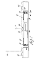
- Figure 2 is a cross-sectional view of the subject invention disposed between two omnidirectional rollerways for conveying an article;
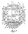
- Figure 3 is a top view of the subject invention;
- Figure 4 is a cross-sectional view taken along lines 4-4 of Figure 3;
- Figure 5 is a cross section of the subject invention taken along lines 5-5 of Figure 3; and
- Figure 6 is a top view of the frame member and support bracket of the subject invention.
- Referring to the Figures, wherein like numerals indicate like or corresponding parts throughout the several views, a steerable low profile power drive assembly according to the subject invention is generally shown at 10. The
power drive assembly 10 is mounted to thefloor 12 of anaircraft 14. Thepower drive assembly 10 is operated in association with a rollerway conveyor system, generally indicated at 16. An article of freight orcargo 18 is shown in Figures 1, 2 and 4 supported on therollerway 16. As in Figures 2 and 4, thecargo 18 may be supported on aflat skid 20. Therefore, therollerway 16 andpower drive assembly 10 form a conveyor path longitudinally within the cargo area of theaircraft 14 and along thefloor 12 so as to allow thecargo 18 to be easily and automatically conveyed along the conveyor path. - As best shown in Figure 1, a plurality of non- steerable
power drive units 21 are disposed in strategic locations along thefloor 12 of theaircraft 14 and in the midst of therollerway 16 so that as theskid 20 andcargo 18 are conveyed along therollerway 16, at least onepower drive assembly skid 20 at all times. A portion of therollerway 16 comprises an omnidirectional area 16' lying directly inside the door area or nose area of the aircraft, and in some instances one additional station forwardly of the door area. The omnidirectional area 16' may comprise either a ball mat or omni-caster system as is well known. A plurality of the subject steerablepower drive assemblies 10 are located in the midst of the omnidirectional area 16'. - The
power drive assembly 10 includes aframe member 22. As shown in the Figures, theframe member 22 is annular and comprises a generally truncated cylinder. Asupport bracket 24 is rotatably connected to theframe member 22 for rotation about a substantially vertical axis A. Thesupport bracket 24 is supported within the annulus of theframe member 22 and is rotatable relative to theframe member 22 about the vertical axis A. - A roller means, generally indicated at 26 in Figures 2, 3 and 4, is supported on the
support bracket 24 for independent rotation about a substantially horizontal axis for rollably engaging the underside of theskid 20 to be conveyed along therollerway 16. A drive means, generally indicated at 28, is operatively connected to the roller means 26 for rotating the roller means 26 about its horizontal axis. More particularly, the roller means 26 and drive means 28 are mounted as a removable modular unit such that, as a power drive unit, the roller means 26 and drive means 28 together may be installed and removed from thesupport bracket 24. That is, the roller means 26 and the drive means 28 comprise a detachable unit having the specific purpose of engaging the underside of the articles and forceably driving them along a conveyor path. Preferably, the modular roller means 26 and drive means 28 comprise one cylindrical roller powered by two separate electric motors. That is, two separate electric motors are operatively engaged with one single roller for providing twice the tractive force available when only one motor is used to power one roller. In Figures 2 and 4, acover 29 is shown attached to the uppermost edge of theframe member 22 for protecting theassembly 10 while providing an opening for the roller means 26. - As shown in Figures 2, 4 and 5, the subject invention is characterized by the
frame member 22 including asubjacent mounting surface 30 disposed below the roller means 26 for attachment to thefloor structure 12 of theaircraft 14 for supporting the roller means 26 entirely above thefloor 12. In other words, thesubjacent mounting surface 30 supports theentire assembly 10 above thefloor 12 of theaircraft 14 such that theentire frame member 22, theentire support bracket 24, the entire roller means 26 and the entire drive means 28 are disposed above the surface of thefloor 12. Thesubjacent mounting surface 30 is situated directly below, or directly beneath, or underlies, theframe member 22. Thesubjacent mounting surface 30 allows theassembly 10 to be installed into theaircraft 14 without the necessity of cutting holes in thefloor 12, and thereby does not impair the structural integrity of thefloor 12. - As the diameter of the
frame member 22 is preferably between twelve and fourteen inches, and the structural cross-members in freighter aircraft are typically twenty inches apart, extensions may be provided radially outwardly of theframe member 22 to support theassembly 10 directly on the structural cross members of the aircraft. Alternatively, many aircrafts converted from passenger service include structural seat tracks along thefloor 12 of the cargo area. The subjacent mountingsurface 30 may be easily modified to mount and attach directly to these seat tracks without requiring that a hole be cut in thefloor 12. - Referring now to Figures 3 and 4, a stabilizer means, generally indicated at 32, is provided for rotatably stabilizing the
support bracket 24 to theframe member 22 to prevent movement of thesupport bracket 24 relative to theframe member 22 in directions axially and laterally of the vertical axis A. That is, the stabilizer means 32 only allows thesupport bracket 24 to rotate relative to theframe member 22 about the vertical axis A, while restraining movement of thesupport bracket 24 relative to theframe member 22 in any other direction. More specifically, the stabilizer means 32 includes a plurality ofupper wheels 34 andlower wheels 36 supported for independent rotation about respective axes extending radially from the vertical axis A. As perhaps best shown in Figure 3, each of thewheels support bracket 24. Thewheels shank portion 38 disposed through an opening in thesupport bracket 24 and secured to thesupport bracket 24 from behind by a threadedfastener 40. - The stabilizer means 32 further includes a
ledge 42 extending radially inwardly from theframe member 22 and spaced vertically above the subjacent mountingsurface 30 for engaging thewheels ledge 42 is mounted to theframe member 22 midway between the subjacent mountingsurface 30 and the upper surface of theframe member 22. A fastener, such as rivet 44, may be employed to secure theledge 42 to theframe member 22. Theledge 42 has anupper race 46 which is disposed in a plane perpendicular to the vertical axis for engaging theupper wheels 34. Theupper race 46 is a substantially flat annulus which provides a smooth rolling surface for theupper wheels 34. Theledge 42 further includes a frustoconicallower race 48 which is concentrically disposed with respect to the vertical axis A for engaging thelower wheels 36. Therefore, as best shown in Figure 4, the upper 34 and lower 36 wheels are effectively clamped on opposite sides of theledge 42. Theupper wheels 34 andupper race 46 prevent downward axial movement of thesupport bracket 24, whereas thelower wheels 36 andlower race 48 prevent upward axial movement of thesupport bracket 24 and lateral movement of thesupport bracket 24. - A motor means, generally indicated at 50 in Figures 3 and 5, is provided for rotating the
support bracket 24 relative to theframe member 22 about the vertical axis A. The motor means 50 includes anelectric motor 52 supported on thesupport bracket 24 adjacent its outer edge. In other words, theelectric motor 52 is fixed to thesupport bracket 24, as illustrated by thefasteners 54 shown in Figure 5. Theelectric motor 52 includes anoutput shaft 56 supported in a bushing in the upper edge portion of thesupport bracket 24. Adrive pinion 58 is fixed on theoutput shaft 56 and operatively engaged with afirst gear 60. Thefirst gear 60 is mounted on ashaft 62, which in turn is supported on opposite ends in bushings in thesupport bracket 24. A first pinion is fixed to thefirst shaft 62, and therefore rotates with thefirst gear 60. Thefirst pinion 64 operatively engages asecond gear 66 supported for rotation between opposite ends on asecond shaft 68. Asecond pinion 70 is supported on thesecond shaft 68 and rotates with thesecond gear 66. Thesecond pinion 70 operatively engages athird gear 72 supported for rotation on athird shaft 74. Athird pinion 76 is fixed on thethird shaft 74 for rotation with thethird gear 72. Thethird pinion 76 operatively engages anoutput gear 78 supported for rotation on theshaft 80. Therefore, theelectric motor 52,first shaft 62,second shaft 68,third shaft 74 andoutput gear shaft 80 are supported for rotation about parallel vertical axes on thesupport bracket 24. Thedrive pinion 58 is operatively connected to theoutput gear 78 through a reduction gear train which effectively reduces the output RPM of theelectric motor 52 while increasing the output torque by a proportional degree. - As shown best in Figure 3, a
ring gear 82 is formed on the radially inward surface of theledge 42 between theupper race 46 and thelower race 48. Thering gear 82 includes a plurality of parallel, vertically extending gear teeth operatively engaged with theoutput gear 78. Therefore, operation of theelectric motor 52 causes theoutput gear 78 to rotate while engaged with thering gear 82, thereby rotating thesupport bracket 24 relative to theframe member 22 about the vertical axis A. Typically, the subjectpower drive assembly 10 is controlled from a remote control station, where a signal is sent to theelectric motor 52. The signal sent to theelectric motor 52 commands theelectric motor 52 to rotate in a certain direction and for a certain period of time thereby rotating thesupport bracket 24 relative to theframe member 22 by a given angle. - Referring to Figures 3 and 6, the
support bracket 24 is shown including afirst receptacle 84 for receiving a modular first roller means 26 and first drive means 28. Thefirst receptacle 84 includes fourperipheral bores 86 for receiving fasteners with which to secure the first modular roller means 26 and drive means 28 to thesupport frame 24. Similarly, thesupport bracket 24 includes a second receptacle 84' for receiving a modular second roller means 26' and second drive means 28'. Likewise, four bores 86' are disposed about the periphery of the second receptacle 84' for securing the second modular unit to thesupport bracket 24. - As perhaps best shown in Figure 6, the
support bracket 24 comprises a skeletal structure whose only function is to support the roller means 26, 26', drive means 28, 28' and upper 34 and lower 36 wheels, along with the motor means 50. The first 84 and second 84' receptacles are disposed in thesupport bracket 24 to receive the first 26 and second 26' roller means for independent rotation about substantially parallel horizontal axes. Thefirst receptacle 84 is disposed to receive the modular first roller means 26 and first drive means 28 in an orientation opposite that of the modular second roller means 26' and second drive means 28'. That is, the modular first roller means 26 and first drive means 28 are disposed 180° rotated from the modular second roller means and second drive means 28 to better nest the assemblies within the limited space. - In known fashion, and as suggested in phantom in Figure 2, the first 26 and second 26' roller means are of the type which move upwardly from a retracted position to engage the under surface of the
article 18 orskid 20 to be conveyed. In this manner, in the event of a power failure, thecargo 18 may be easily moved along therollerway 16 without overcoming the dynamic braking action of the drive means 28, 28'. - The subject invention is particularly advantageous in that the steerable
power drive assembly 10 may be floor mounted, whereas the prior art required a recessed mounting underneath the floor of the aircraft. By floor mounting thesubject assembly 10, theaircraft 14 is not permanently scarred or weakened. Also, the structure is much more compact that has heretofore been known, and lighter in weight so that the aircraft may carry larger quantities of freight. Further, thesubject invention 10 is much more easily installed in the aircraft as it may be easily bolted to the existingfloor 12, whereas the prior art requires a time consuming mounting procedure including the cutting of holes in the aircraft floor. - The invention has been described in an illustrative manner, and it is to be understood that the terminology which has been used is intended to be in the nature of words of description rather than of limitation.
- Obviously, many modifications and variations of the present invention are possible in light of the above teachings. It is, therefore, to be understood that within the scope of the appended claims wherein reference numerals are merely for convenience and are not to be in any way limiting, the invention may be practiced otherwise than as specifically described.
Claims (15)
Applications Claiming Priority (2)
| Application Number | Priority Date | Filing Date | Title |
|---|---|---|---|
| US54298190A | 1990-06-25 | 1990-06-25 | |
| US542981 | 1990-06-25 |
Publications (2)
| Publication Number | Publication Date |
|---|---|
| EP0464981A1 true EP0464981A1 (en) | 1992-01-08 |
| EP0464981B1 EP0464981B1 (en) | 1994-08-17 |
Family
ID=24166108
Family Applications (1)
| Application Number | Title | Priority Date | Filing Date |
|---|---|---|---|
| EP19910302140 Expired - Lifetime EP0464981B1 (en) | 1990-06-25 | 1991-03-13 | Low profile steerable power drive unit |
Country Status (4)
| Country | Link |
|---|---|
| EP (1) | EP0464981B1 (en) |
| JP (1) | JPH0749332B2 (en) |
| CA (1) | CA2038821C (en) |
| DE (1) | DE69103485T2 (en) |
Cited By (3)
| Publication number | Priority date | Publication date | Assignee | Title |
|---|---|---|---|---|
| EP1473222A1 (en) * | 2003-04-30 | 2004-11-03 | Telair International GmbH | Cargo deck for aircraft |
| CN108001992A (en) * | 2017-12-26 | 2018-05-08 | 清远欧派集成家居有限公司 | Workpiece transfer platform |
| EP4163205A1 (en) * | 2021-10-05 | 2023-04-12 | Airbus Operations GmbH | Movable cargo transport platform for being received in an aircraft cargo hold or cabin having separately steerable wheel assemblies and cargo transport system |
Citations (3)
| Publication number | Priority date | Publication date | Assignee | Title |
|---|---|---|---|---|
| US3978975A (en) * | 1975-06-30 | 1976-09-07 | The Boeing Company | Cargo power drive unit |
| US4589542A (en) * | 1983-12-19 | 1986-05-20 | The Boeing Company | Cargo drive unit |
| EP0355251A1 (en) * | 1988-08-19 | 1990-02-28 | Bavaria Cargo Technologie Gmbh | Drive roller unit |
Family Cites Families (1)
| Publication number | Priority date | Publication date | Assignee | Title |
|---|---|---|---|---|
| JPS555050A (en) * | 1978-06-27 | 1980-01-14 | Toshiba Corp | Method of winding coil of motor |
-
1991
- 1991-03-13 DE DE1991603485 patent/DE69103485T2/en not_active Expired - Fee Related
- 1991-03-13 EP EP19910302140 patent/EP0464981B1/en not_active Expired - Lifetime
- 1991-03-21 CA CA 2038821 patent/CA2038821C/en not_active Expired - Fee Related
- 1991-06-24 JP JP3151303A patent/JPH0749332B2/en not_active Expired - Lifetime
Patent Citations (3)
| Publication number | Priority date | Publication date | Assignee | Title |
|---|---|---|---|---|
| US3978975A (en) * | 1975-06-30 | 1976-09-07 | The Boeing Company | Cargo power drive unit |
| US4589542A (en) * | 1983-12-19 | 1986-05-20 | The Boeing Company | Cargo drive unit |
| EP0355251A1 (en) * | 1988-08-19 | 1990-02-28 | Bavaria Cargo Technologie Gmbh | Drive roller unit |
Cited By (5)
| Publication number | Priority date | Publication date | Assignee | Title |
|---|---|---|---|---|
| EP1473222A1 (en) * | 2003-04-30 | 2004-11-03 | Telair International GmbH | Cargo deck for aircraft |
| US7073994B2 (en) | 2003-04-30 | 2006-07-11 | Telair International Gmbh | Cargo deck for an aircraft |
| CN108001992A (en) * | 2017-12-26 | 2018-05-08 | 清远欧派集成家居有限公司 | Workpiece transfer platform |
| CN108001992B (en) * | 2017-12-26 | 2024-04-16 | 清远欧派集成家居有限公司 | Workpiece transfer platform |
| EP4163205A1 (en) * | 2021-10-05 | 2023-04-12 | Airbus Operations GmbH | Movable cargo transport platform for being received in an aircraft cargo hold or cabin having separately steerable wheel assemblies and cargo transport system |
Also Published As
| Publication number | Publication date |
|---|---|
| JPH0749332B2 (en) | 1995-05-31 |
| JPH04226205A (en) | 1992-08-14 |
| CA2038821C (en) | 1993-08-17 |
| EP0464981B1 (en) | 1994-08-17 |
| DE69103485D1 (en) | 1994-09-22 |
| DE69103485T2 (en) | 1994-12-08 |
| CA2038821A1 (en) | 1991-12-26 |
Similar Documents
| Publication | Publication Date | Title |
|---|---|---|
| US5101962A (en) | Low profile steerable power drive unit | |
| US5314143A (en) | Aircraft cabin construction | |
| EP0481587B1 (en) | Dual motor cargo drive unit | |
| EP1415908B1 (en) | Cargo loading system | |
| US5383630A (en) | Main deck quick change cargo system | |
| EP0338020B1 (en) | Method and apparatus to enhance intermodal containers for cargo transport | |
| US6454208B1 (en) | Automated galley-cart storage system | |
| US6776263B2 (en) | Elevator system for the vertical transport of loads in an aircraft | |
| US6315109B1 (en) | Split roller wheel and method of assembly | |
| AU760344B2 (en) | Material handling unit with multidirectional helical roller assemblies | |
| EP1279592B1 (en) | Aircraft overhead galley/crew rest facility | |
| US7090068B2 (en) | Palette conveyance mechanism and assembling line using it | |
| US4544319A (en) | Cargo transfer system | |
| US4746258A (en) | Floating table for article transport vehicle | |
| US12049327B2 (en) | Latches for cargo hold loading and storage system and associated methods | |
| US12589894B1 (en) | Highly adaptable platform | |
| CA2056331A1 (en) | Modular cargo drive unit for a conveyor | |
| HK1005710B (en) | Device for loading packages into a storage hold of an aircraft | |
| HK1005710A1 (en) | Device for loading packages into a storage hold of an aircraft | |
| US7717252B2 (en) | Cargo power drive unit with uniform bi-directional drive traction | |
| EP0464981B1 (en) | Low profile steerable power drive unit | |
| EP3156329B1 (en) | System for moving loads and cargo hold | |
| JPS58177760A (en) | Controllable distribution type conveyor | |
| US4650066A (en) | Retractable drive assembly for conveyor | |
| US11365005B2 (en) | Caster assembly for cargo handling system |
Legal Events
| Date | Code | Title | Description |
|---|---|---|---|
| PUAI | Public reference made under article 153(3) epc to a published international application that has entered the european phase |
Free format text: ORIGINAL CODE: 0009012 |
|
| AK | Designated contracting states |
Kind code of ref document: A1 Designated state(s): BE CH DE FR GB IT LI |
|
| 17P | Request for examination filed |
Effective date: 19920312 |
|
| 17Q | First examination report despatched |
Effective date: 19930420 |
|
| ITF | It: translation for a ep patent filed | ||
| GRAA | (expected) grant |
Free format text: ORIGINAL CODE: 0009210 |
|
| AK | Designated contracting states |
Kind code of ref document: B1 Designated state(s): BE CH DE FR GB IT LI |
|
| REF | Corresponds to: |
Ref document number: 69103485 Country of ref document: DE Date of ref document: 19940922 |
|
| ET | Fr: translation filed | ||
| PLBE | No opposition filed within time limit |
Free format text: ORIGINAL CODE: 0009261 |
|
| STAA | Information on the status of an ep patent application or granted ep patent |
Free format text: STATUS: NO OPPOSITION FILED WITHIN TIME LIMIT |
|
| 26N | No opposition filed | ||
| PGFP | Annual fee paid to national office [announced via postgrant information from national office to epo] |
Ref country code: FR Payment date: 19960126 Year of fee payment: 6 |
|
| PGFP | Annual fee paid to national office [announced via postgrant information from national office to epo] |
Ref country code: CH Payment date: 19960325 Year of fee payment: 6 |
|
| PGFP | Annual fee paid to national office [announced via postgrant information from national office to epo] |
Ref country code: BE Payment date: 19960502 Year of fee payment: 6 |
|
| PG25 | Lapsed in a contracting state [announced via postgrant information from national office to epo] |
Ref country code: CH Effective date: 19970331 Ref country code: BE Effective date: 19970331 Ref country code: LI Effective date: 19970331 |
|
| BERE | Be: lapsed |
Owner name: TELEFLEX INC. Effective date: 19970331 |
|
| REG | Reference to a national code |
Ref country code: CH Ref legal event code: PL |
|
| PG25 | Lapsed in a contracting state [announced via postgrant information from national office to epo] |
Ref country code: FR Free format text: LAPSE BECAUSE OF NON-PAYMENT OF DUE FEES Effective date: 19971128 |
|
| REG | Reference to a national code |
Ref country code: FR Ref legal event code: ST |
|
| REG | Reference to a national code |
Ref country code: GB Ref legal event code: IF02 |
|
| PG25 | Lapsed in a contracting state [announced via postgrant information from national office to epo] |
Ref country code: IT Free format text: LAPSE BECAUSE OF NON-PAYMENT OF DUE FEES;WARNING: LAPSES OF ITALIAN PATENTS WITH EFFECTIVE DATE BEFORE 2007 MAY HAVE OCCURRED AT ANY TIME BEFORE 2007. THE CORRECT EFFECTIVE DATE MAY BE DIFFERENT FROM THE ONE RECORDED. Effective date: 20050313 |
|
| PGFP | Annual fee paid to national office [announced via postgrant information from national office to epo] |
Ref country code: DE Payment date: 20090327 Year of fee payment: 19 |
|
| PGFP | Annual fee paid to national office [announced via postgrant information from national office to epo] |
Ref country code: GB Payment date: 20090403 Year of fee payment: 19 |
|
| GBPC | Gb: european patent ceased through non-payment of renewal fee |
Effective date: 20100313 |
|
| PG25 | Lapsed in a contracting state [announced via postgrant information from national office to epo] |
Ref country code: DE Free format text: LAPSE BECAUSE OF NON-PAYMENT OF DUE FEES Effective date: 20101001 |
|
| PG25 | Lapsed in a contracting state [announced via postgrant information from national office to epo] |
Ref country code: GB Free format text: LAPSE BECAUSE OF NON-PAYMENT OF DUE FEES Effective date: 20100313 |