EP0468426B1 - Classifier for powdery material - Google Patents
Classifier for powdery material Download PDFInfo
- Publication number
- EP0468426B1 EP0468426B1 EP91112283A EP91112283A EP0468426B1 EP 0468426 B1 EP0468426 B1 EP 0468426B1 EP 91112283 A EP91112283 A EP 91112283A EP 91112283 A EP91112283 A EP 91112283A EP 0468426 B1 EP0468426 B1 EP 0468426B1
- Authority
- EP
- European Patent Office
- Prior art keywords
- casing
- vane wheel
- classifier
- outlet pipe
- inlet port
- Prior art date
- Legal status (The legal status is an assumption and is not a legal conclusion. Google has not performed a legal analysis and makes no representation as to the accuracy of the status listed.)
- Expired - Lifetime
Links
- 239000000463 material Substances 0.000 title claims description 12
- 239000011362 coarse particle Substances 0.000 claims description 21
- 238000007599 discharging Methods 0.000 claims description 3
- 239000000203 mixture Substances 0.000 description 22
- 239000010419 fine particle Substances 0.000 description 13
- 230000000694 effects Effects 0.000 description 10
- 239000002245 particle Substances 0.000 description 3
- 238000009987 spinning Methods 0.000 description 2
- 230000015572 biosynthetic process Effects 0.000 description 1
- 230000007423 decrease Effects 0.000 description 1
- 230000003247 decreasing effect Effects 0.000 description 1
- 230000005484 gravity Effects 0.000 description 1
- 239000007788 liquid Substances 0.000 description 1
- XLYOFNOQVPJJNP-UHFFFAOYSA-N water Substances O XLYOFNOQVPJJNP-UHFFFAOYSA-N 0.000 description 1
Images


Classifications
-
- B—PERFORMING OPERATIONS; TRANSPORTING
- B04—CENTRIFUGAL APPARATUS OR MACHINES FOR CARRYING-OUT PHYSICAL OR CHEMICAL PROCESSES
- B04C—APPARATUS USING FREE VORTEX FLOW, e.g. CYCLONES
- B04C5/00—Apparatus in which the axial direction of the vortex is reversed
- B04C5/12—Construction of the overflow ducting, e.g. diffusing or spiral exits
- B04C5/13—Construction of the overflow ducting, e.g. diffusing or spiral exits formed as a vortex finder and extending into the vortex chamber; Discharge from vortex finder otherwise than at the top of the cyclone; Devices for controlling the overflow
-
- B—PERFORMING OPERATIONS; TRANSPORTING
- B04—CENTRIFUGAL APPARATUS OR MACHINES FOR CARRYING-OUT PHYSICAL OR CHEMICAL PROCESSES
- B04C—APPARATUS USING FREE VORTEX FLOW, e.g. CYCLONES
- B04C5/00—Apparatus in which the axial direction of the vortex is reversed
- B04C5/08—Vortex chamber constructions
- B04C5/103—Bodies or members, e.g. bulkheads, guides, in the vortex chamber
-
- B—PERFORMING OPERATIONS; TRANSPORTING
- B04—CENTRIFUGAL APPARATUS OR MACHINES FOR CARRYING-OUT PHYSICAL OR CHEMICAL PROCESSES
- B04C—APPARATUS USING FREE VORTEX FLOW, e.g. CYCLONES
- B04C9/00—Combinations with other devices, e.g. fans, expansion chambers, diffusors, water locks
-
- B—PERFORMING OPERATIONS; TRANSPORTING
- B07—SEPARATING SOLIDS FROM SOLIDS; SORTING
- B07B—SEPARATING SOLIDS FROM SOLIDS BY SIEVING, SCREENING, SIFTING OR BY USING GAS CURRENTS; SEPARATING BY OTHER DRY METHODS APPLICABLE TO BULK MATERIAL, e.g. LOOSE ARTICLES FIT TO BE HANDLED LIKE BULK MATERIAL
- B07B7/00—Selective separation of solid materials carried by, or dispersed in, gas currents
- B07B7/08—Selective separation of solid materials carried by, or dispersed in, gas currents using centrifugal force
- B07B7/083—Selective separation of solid materials carried by, or dispersed in, gas currents using centrifugal force generated by rotating vanes, discs, drums, or brushes
-
- B—PERFORMING OPERATIONS; TRANSPORTING
- B04—CENTRIFUGAL APPARATUS OR MACHINES FOR CARRYING-OUT PHYSICAL OR CHEMICAL PROCESSES
- B04C—APPARATUS USING FREE VORTEX FLOW, e.g. CYCLONES
- B04C9/00—Combinations with other devices, e.g. fans, expansion chambers, diffusors, water locks
- B04C2009/002—Combinations with other devices, e.g. fans, expansion chambers, diffusors, water locks with external filters
Definitions
- This invention relates to a classifier for classifying powdery material in gas according to their particle size and specific gravity.
- the preamble of claim 1 is delimited to the state of the art disclosed in US-A-4 260 478.
- Fig. 3 shows such a prior art classifier of this type. It has a cylindrical casing 1 provided at the upper part thereof with an inlet port 2 for the material to be classified which extends in a tangential direction with respect to the inner wall of the casing. Material-air mixture a is fed into the casing 1 through the inlet port 2 in the tangential direction, forming a vortex in the casing. Coarse particles are classified by the cyclone effect due to the vortex.
- An externally driven vane wheel 3 is mounted in the upper part of the casing 1. It serves to blow off any unclassified coarse particles going toward an outlet port 7 outwards by imparting centrifugal force thereto, thereby separating any fine particles. Thus it serves to improve the classifying effect.
- the material-air mixture thus classified flows out of the casing through the outlet port 7 and is collected in a collector (not shown) such as a bag filter.
- a gas (air) inlet port 4 is formed in the lower part of the casing 1. Air b fed into the casing 1 through the inlet port 4 forms an upward vortex by spinning vanes 5 (see Fig. 2d). The upward air current b separates any fine particles from the coarse particles and flows out through the outlet port 7 together with the separated fine particles.
- the coarse particles c thus classified are discharged through a discharge port 6 formed in the bottom of the casing 1.
- the vane wheel 3 comprises an inverted conical member 3a at its bottom, a disc 3b formed with a through hole and a plurality of vanes 3c provided between the conical member 3a and the disc 3b and arranged at equal angular intervals from one another.
- the material-air mixture a tends to reach the vane wheel 3 without sufficiently undergoing the cyclone effect.
- the density of the material-air mixture a is high, i.e. the air contains large amounts of coarse particles when it reaches the vane wheel 3.
- the vane wheel 3 suffers from a large load and gets worn rather severely.
- the higher the density of the mixture the lower the accuracy of classification and the more easily the coarse particles flow out through the outlet port 7.
- An object of this invention is to provide a classifier in which the classification by the vane wheel can be carried out in a low-density condition.
- an outlet pipe is provided so as to protrude into the casing through its top and an externally-driven vane wheel is provided under the outlet pipe in a concentric relationship with respect to the casing.
- An inlet port for introducing the material to be classified and air mixture (hereinafter referred to as the material-air mixture) in a tangential direction is provided at a higher level than the bottom end of the outlet pipe.
- An inlet for air is provided at a lower level than said vane wheel to introduce air into the casing in the same tangential direction as the tangential direction in which the material to be classified is introduced.
- a conical member is provided adjacent to the inlet for introducing air.
- a cylindrical body is provided between the inner wall of the casing and the vane wheel at predetermined distances from the casing and the vane wheel. It has at its top a small-diameter portion. The abovesaid distances and the diameter of the small-diameter portion are decided to suitable values, taking the classification efficiency into consideration.
- the vertical position of the cylindrical body is adjustable.
- the material-air mixture is introduced into the casing through the inlet port with the vane wheel in rotation.
- the mixture flows in a tangential direction with respect to the inner wall of the casing and goes down in a vortex around the outlet pipe.
- Coarse particles in the material are classified by the cyclone effect on the downward vortex and flow down along the inner wall of the casing and are discharged through the discharge pipe.
- the inlet port for the material is located higher than the bottom opening of the outlet pipe, the mixture flows down whirling round for the length of the outlet pipe till it reaches the vane wheel and thus can be classified sufficiently by the cyclone effect. Namely, the vane wheel is turned in a lower density condition than is the prior art vane wheel.
- the cylindrical body may be mounted around the vane wheel with its top end reduced in diameter so as to be sufficiently close to the outer periphery of the vane wheel. It serves to divide the vane wheel into upper and lower parts and the space between the vane wheel and the inner wall of the casing into two parts.
- the current carrying fine particles scarcely mixes with the downward flow of coarse particles, because though the coarse particles classified by the cyclone effect tend to go toward the center of the casing as they fall, they are blocked by the cylindrical body.
- the current carrying fine particles formed by the cyclone effect enters in the form of a laminar flow into the top part of the vane wheel and classified. Then it flows out through the outlet pipe.
- the area ratio between the two passages leading to the outlet pipe, i.e. the passage formed at the portion of the vane wheel not surrounded by the cylindrical body and the passage formed at its surrounded portion is adjustable.
- the particle size of classification is adjustable.
- the vane wheel can be turned in a low-density condition by providing the outlet pipe in the casing.
- the material can be classified with high accuracy and the vanes are protected against wear.
- a cylindrical casing 10 has its top closed by a top plate 10a.
- An outlet pipe 11 for discharging air containing fine particles extends through the center of the top plate 10a and protrudes into the casing 10.
- An inlet port 12 for air mixed with the material to be classified is provided at the top end of the casing 10.
- a vane wheel 13 is provided under the outlet pipe 11 and is rotatably supported by a bearing 14 provided on top of the outlet pipe 11 and a bearing 14' provided on top of a conical tube 18 (described later). It is driven by an external motor. Its turning speed is suitably determined taking into account the classifying efficiency.
- the vane wheel 13 has a plurality of vanes 13a arranged at angularly equal intervals and each extending obliquely inwards with respect to the direction of rotation. When the vane wheel 13 rotates, the particles will touch the vanes 13a and be driven obliquely outward by the skewed surfaces of the vanes. Namely, they are classified by centrifugal force.
- a cylindrical body 15 is provided to partially surround the vane wheel 13 and is fixed in position to the casing 10 by three threaded shafts 16 arranged at equal angular intervals. By turning their nuts 17, the threaded shafts 16 can be moved up and down together with the cylindrical body 15.
- Conical tubes 18 and 23 are provided under the vane wheel 13 and supported by arms 19 and vanes 21 (described later), respectively.
- the casing 10 has two air inlet ports 20 at lower part thereof. As shown in Fig. 2d, they are provided at diametrically opposite positions and extend in a tangential direction with respect to the inner wall of the casing 10. Since air b is fed tangentially into the casing 10 through the inlet ports 20, a vortex is formed in the casing. As shown in Fig. 2d, spinning vanes 21 are provided in the casing 10 to face the inlet ports 20. The vanes 21 and the conical tube 23 contribute to a smooth formation of vortex.
- the casing 10 has an inverted conical bottom portion and is formed in the bottom end thereof with a discharge port 22 for discharging the coarse particles.
- a discharge pipe (not shown) is connected to the discharge port 22.
- the material-air mixture a While the material-air mixture a flows down along the outlet pipe 11, it undergoes a sufficient cyclone effect until it reaches the vane wheel 13, whereupon any remaining coarse particles c are scattered outwardly by the centrifugal force due to the rotation of the vane wheel 13. At the same time, fine particles adhering to the coarse particles are disengaged therefrom.
- the material-air mixture a thus reclassified and containing only fine particles flows up into the outlet pipe 11 through its bottom opening and is sent to the next step such as a bag filter.
- the classified coarse particles c flow down guided by the cylindrical body 15 and the conical tube 23. On their way down, fine particles adhering thereto are disengaged by the cyclone effect due to the vortex of air flowing into the casing 10 through the inlet ports 20. The vortex carrying the fine particles reaches the vane wheel 13 and is classified thereby. Then it flows out of the casing 10 through the outlet pipe 11.
- the degree of classification is adjusted by changing the height of the cylindrical body 15 and thus the area of the vane wheel 13 surrounded by the body 15. Namely, when the body 15 is raised, the area of the vane wheel 13 not surrounded by the cylindrical body 15 decreases, thus narrowing the sectional area of the passage through which the material-air mixture a can flow into the outlet pipe 11. This will speed up the flow of the mixture a . Thus the coarse particles tend to be carried by the mixture a . When the body 15 is lowered, the area of the passage for the mixture expands, thus decreasing the flow speed. This will reduce the tendency to carry the coarse particles, reducing the size of classification.
- the flow rate of air through the air inlet ports 20 has to be changed according to the area of the vane wheel 13 surrounded by the cylindrical body 15, i.e. the area of passage leading to the outlet pipe 11. Namely, the flow rate of air has to be adjusted so that the classification size at the lower part of the vane wheel 13 surrounded by the body 15 is equal to the classification size at its upper part not covered by the body 15.
- the classification size can be changed by adjusting the height of the cylindrical body 15, the flow rate of air through the air inlet ports 20 and the revolving speed of the vane wheel 13.
- classification is carried out by use of air. But any other gas or a liquid such as water may be used instead.
Landscapes
- Cyclones (AREA)
- Combined Means For Separation Of Solids (AREA)
- Separation Of Solids By Using Liquids Or Pneumatic Power (AREA)
Description
- This invention relates to a classifier for classifying powdery material in gas according to their particle size and specific gravity. The preamble of claim 1 is delimited to the state of the art disclosed in US-A-4 260 478.
- Fig. 3 shows such a prior art classifier of this type. It has a cylindrical casing 1 provided at the upper part thereof with an
inlet port 2 for the material to be classified which extends in a tangential direction with respect to the inner wall of the casing. Material-air mixture a is fed into the casing 1 through theinlet port 2 in the tangential direction, forming a vortex in the casing. Coarse particles are classified by the cyclone effect due to the vortex. - An externally driven
vane wheel 3 is mounted in the upper part of the casing 1. It serves to blow off any unclassified coarse particles going toward anoutlet port 7 outwards by imparting centrifugal force thereto, thereby separating any fine particles. Thus it serves to improve the classifying effect. The material-air mixture thus classified flows out of the casing through theoutlet port 7 and is collected in a collector (not shown) such as a bag filter. - A gas (air) inlet port 4 is formed in the lower part of the casing 1. Air b fed into the casing 1 through the inlet port 4 forms an upward vortex by spinning vanes 5 (see Fig. 2d). The upward air current b separates any fine particles from the coarse particles and flows out through the
outlet port 7 together with the separated fine particles. - The coarse particles c thus classified are discharged through a
discharge port 6 formed in the bottom of the casing 1. - The
vane wheel 3 comprises an invertedconical member 3a at its bottom, adisc 3b formed with a through hole and a plurality ofvanes 3c provided between theconical member 3a and thedisc 3b and arranged at equal angular intervals from one another. - In this type of apparatus, since the
inlet port 2 and thevane wheel 3 are located on the same level as is apparent from Fig. 3, the material-air mixture a tends to reach thevane wheel 3 without sufficiently undergoing the cyclone effect. Thus, the density of the material-air mixture a is high, i.e. the air contains large amounts of coarse particles when it reaches thevane wheel 3. As a result, thevane wheel 3 suffers from a large load and gets worn rather severely. Also, the higher the density of the mixture, the lower the accuracy of classification and the more easily the coarse particles flow out through theoutlet port 7. - An object of this invention is to provide a classifier in which the classification by the vane wheel can be carried out in a low-density condition.
- In accordance with the present invention, an outlet pipe is provided so as to protrude into the casing through its top and an externally-driven vane wheel is provided under the outlet pipe in a concentric relationship with respect to the casing. An inlet port for introducing the material to be classified and air mixture (hereinafter referred to as the material-air mixture) in a tangential direction is provided at a higher level than the bottom end of the outlet pipe.
- An inlet for air is provided at a lower level than said vane wheel to introduce air into the casing in the same tangential direction as the tangential direction in which the material to be classified is introduced. A conical member is provided adjacent to the inlet for introducing air.
- A cylindrical body is provided between the inner wall of the casing and the vane wheel at predetermined distances from the casing and the vane wheel. It has at its top a small-diameter portion. The abovesaid distances and the diameter of the small-diameter portion are decided to suitable values, taking the classification efficiency into consideration. The vertical position of the cylindrical body is adjustable.
- According to this invention, the material-air mixture is introduced into the casing through the inlet port with the vane wheel in rotation. The mixture flows in a tangential direction with respect to the inner wall of the casing and goes down in a vortex around the outlet pipe. Coarse particles in the material are classified by the cyclone effect on the downward vortex and flow down along the inner wall of the casing and are discharged through the discharge pipe.
- When the mixture reaches the vane wheel, any remaining coarse particles are scattered outwardly by the centrifugal force applied by the rotation of the vane wheel. At the same time, fine particles adhering to the coarse particles are disengaged. The mixture thus reclassified which contains only fine particles are fed into the outlet pipe through its bottom opening and sent to the next step.
- Since the inlet port for the material is located higher than the bottom opening of the outlet pipe, the mixture flows down whirling round for the length of the outlet pipe till it reaches the vane wheel and thus can be classified sufficiently by the cyclone effect. Namely, the vane wheel is turned in a lower density condition than is the prior art vane wheel.
- By providing the inlet ports for gas in the lower part of the casing, falling coarse particles can be reclassified in the same manner as with the prior art. Further, by the provision of the conical member, the gas introduced through the inlet port can be smoothly put into whirling motion. This improves the classification efficiency.
- The cylindrical body may be mounted around the vane wheel with its top end reduced in diameter so as to be sufficiently close to the outer periphery of the vane wheel. It serves to divide the vane wheel into upper and lower parts and the space between the vane wheel and the inner wall of the casing into two parts. Thus, the current carrying fine particles scarcely mixes with the downward flow of coarse particles, because though the coarse particles classified by the cyclone effect tend to go toward the center of the casing as they fall, they are blocked by the cylindrical body.
- The current carrying fine particles formed by the cyclone effect enters in the form of a laminar flow into the top part of the vane wheel and classified. Then it flows out through the outlet pipe.
- Since inward flow of the coarse particles is blocked by the cylindrical body, they are guided along the cylindrical body toward the inner wall of the casing, where they are classified by contact with the whirling current from the inlet ports. The current carrying fine particles reaches the vane wheel and classified. Then it flows out through the outlet pipe.
- By moving the cylindrical body up and down, the area ratio between the two passages leading to the outlet pipe, i.e. the passage formed at the portion of the vane wheel not surrounded by the cylindrical body and the passage formed at its surrounded portion is adjustable. Thus, the particle size of classification is adjustable.
- According to this invention, even if a high-density mixture is used, the vane wheel can be turned in a low-density condition by providing the outlet pipe in the casing. Thus, the material can be classified with high accuracy and the vanes are protected against wear.
- Also, by the addition of the inlet ports at the lower part of the casing, and of the conical member and the cylindrical body, more accurate classification becomes possible. Further, by moving the cylindrical body up and down, the classification size can be changed.
- Other features and objects of the present invention will become apparent from the following description taken with reference to the accompanying drawings, in which:
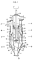
- Fig. 1 is a schematic sectional view of one embodiment of the classifier according to this invention;
- Figs. 2a - 2d are sectional views taken along lines A-A, B-B, C-C and D-D in Fig. 1, respectively; and
- Fig. 3 is a schematic sectional view of a prior art classifier.
- As shown in Fig. 1, a
cylindrical casing 10 has its top closed by a top plate 10a. Anoutlet pipe 11 for discharging air containing fine particles extends through the center of the top plate 10a and protrudes into thecasing 10. Aninlet port 12 for air mixed with the material to be classified is provided at the top end of thecasing 10. - A
vane wheel 13 is provided under theoutlet pipe 11 and is rotatably supported by abearing 14 provided on top of theoutlet pipe 11 and a bearing 14' provided on top of a conical tube 18 (described later). It is driven by an external motor. Its turning speed is suitably determined taking into account the classifying efficiency. As shown in Figs. 2b and 2c, thevane wheel 13 has a plurality ofvanes 13a arranged at angularly equal intervals and each extending obliquely inwards with respect to the direction of rotation. When thevane wheel 13 rotates, the particles will touch thevanes 13a and be driven obliquely outward by the skewed surfaces of the vanes. Namely, they are classified by centrifugal force. - A
cylindrical body 15 is provided to partially surround thevane wheel 13 and is fixed in position to thecasing 10 by three threadedshafts 16 arranged at equal angular intervals. By turning theirnuts 17, the threadedshafts 16 can be moved up and down together with thecylindrical body 15. -
Conical tubes vane wheel 13 and supported byarms 19 and vanes 21 (described later), respectively. Thecasing 10 has twoair inlet ports 20 at lower part thereof. As shown in Fig. 2d, they are provided at diametrically opposite positions and extend in a tangential direction with respect to the inner wall of thecasing 10. Since air b is fed tangentially into thecasing 10 through theinlet ports 20, a vortex is formed in the casing. As shown in Fig. 2d, spinningvanes 21 are provided in thecasing 10 to face theinlet ports 20. Thevanes 21 and theconical tube 23 contribute to a smooth formation of vortex. - The
casing 10 has an inverted conical bottom portion and is formed in the bottom end thereof with adischarge port 22 for discharging the coarse particles. A discharge pipe (not shown) is connected to thedischarge port 22. - In operation, when the material-air mixture a is introduced into the
casing 10 through theinlet port 12 with thevane wheel 13 in rotation, the mixture flows in a tangential direction with respect to the inner wall of thecasing 10 and moves down around theoutlet pipe 11 in a downward vortex. Coarse particles c in the material-air mixture a are classified by the cyclone effect due to the downward vortex and sink down along the inner wall of casing 10 guided by thecylindrical body 15. - While the material-air mixture a flows down along the
outlet pipe 11, it undergoes a sufficient cyclone effect until it reaches thevane wheel 13, whereupon any remaining coarse particles c are scattered outwardly by the centrifugal force due to the rotation of thevane wheel 13. At the same time, fine particles adhering to the coarse particles are disengaged therefrom. The material-air mixture a thus reclassified and containing only fine particles flows up into theoutlet pipe 11 through its bottom opening and is sent to the next step such as a bag filter. - On the other hand, the classified coarse particles c flow down guided by the
cylindrical body 15 and theconical tube 23. On their way down, fine particles adhering thereto are disengaged by the cyclone effect due to the vortex of air flowing into thecasing 10 through theinlet ports 20. The vortex carrying the fine particles reaches thevane wheel 13 and is classified thereby. Then it flows out of thecasing 10 through theoutlet pipe 11. - The degree of classification is adjusted by changing the height of the
cylindrical body 15 and thus the area of thevane wheel 13 surrounded by thebody 15. Namely, when thebody 15 is raised, the area of thevane wheel 13 not surrounded by thecylindrical body 15 decreases, thus narrowing the sectional area of the passage through which the material-air mixture a can flow into theoutlet pipe 11. This will speed up the flow of the mixture a. Thus the coarse particles tend to be carried by the mixture a. When thebody 15 is lowered, the area of the passage for the mixture expands, thus decreasing the flow speed. This will reduce the tendency to carry the coarse particles, reducing the size of classification. - The flow rate of air through the
air inlet ports 20 has to be changed according to the area of thevane wheel 13 surrounded by thecylindrical body 15, i.e. the area of passage leading to theoutlet pipe 11. Namely, the flow rate of air has to be adjusted so that the classification size at the lower part of thevane wheel 13 surrounded by thebody 15 is equal to the classification size at its upper part not covered by thebody 15. - Thus, the classification size can be changed by adjusting the height of the
cylindrical body 15, the flow rate of air through theair inlet ports 20 and the revolving speed of thevane wheel 13. - In the embodiment, classification is carried out by use of air. But any other gas or a liquid such as water may be used instead.
Claims (5)
- A classifier for powdery material, comprising a cylindrical casing (10) formed at an upper portion thereof with an inlet port (12) for introducing the material to be classified into said casing (10) in a tangential direction with respect to an inner wall thereof, said casing having a lower conical portion (23) formed in its bottom end with an opening connected to a discharge pipe (22) for discharging coarse particles and an externally-driven vane wheel (13) provided under an outlet pipe (11) in a concentric relationship with respect to said casing (10), characterised in that the outlet pipe (11) protruds into said casing through its top and said inlet port (12) is located higher than the bottom end of said outlet pipe (11).
- A classifier as claimed in claim 1, wherein said casing (10) is further formed at a location lower than said vane wheel (13) with an air inlet port (20) for introducing air into said casing (10) in substantially the same tangential direction as said tangential direction in which said material to be classified is introduced.
- A classifier as claimed in claim 2, further comprising a conical member provided adjacent to said air inlet port (20).
- A classifier as claimed in any of claims 1 - 3, further comprising a cylindrical body (15) provided between said vane wheel (13) and the inner wall of said casing (10) at a predetermined distance from both said casing (10) and said vane wheel (13), said cylindrical body (15) having a top small-diameter portion located closer to the outer periphery of said vane wheel (13) than the other portion thereof.
- A classifier as claimed in claim 4, wherein said cylindrical (15) body is vertically movable.
Applications Claiming Priority (2)
| Application Number | Priority Date | Filing Date | Title |
|---|---|---|---|
| JP2196701A JP2509374B2 (en) | 1990-07-23 | 1990-07-23 | Granule classifier |
| JP196701/90 | 1990-07-23 |
Publications (3)
| Publication Number | Publication Date |
|---|---|
| EP0468426A2 EP0468426A2 (en) | 1992-01-29 |
| EP0468426A3 EP0468426A3 (en) | 1992-03-04 |
| EP0468426B1 true EP0468426B1 (en) | 1993-12-29 |
Family
ID=16362151
Family Applications (1)
| Application Number | Title | Priority Date | Filing Date |
|---|---|---|---|
| EP91112283A Expired - Lifetime EP0468426B1 (en) | 1990-07-23 | 1991-07-22 | Classifier for powdery material |
Country Status (6)
| Country | Link |
|---|---|
| US (1) | US5201422A (en) |
| EP (1) | EP0468426B1 (en) |
| JP (1) | JP2509374B2 (en) |
| AU (1) | AU625591B2 (en) |
| CA (1) | CA2047494A1 (en) |
| DE (1) | DE69100883T2 (en) |
Cited By (1)
| Publication number | Priority date | Publication date | Assignee | Title |
|---|---|---|---|---|
| DE10352525B4 (en) * | 2003-11-05 | 2009-03-05 | Neuman & Esser Gmbh Mahl- Und Sichtsysteme | cyclone separator |
Families Citing this family (20)
| Publication number | Priority date | Publication date | Assignee | Title |
|---|---|---|---|---|
| DE4416757C2 (en) * | 1994-05-13 | 1997-04-10 | Zeppelin Schuettguttech Gmbh | Deflection-counterflow classifier |
| US5713972A (en) * | 1994-07-18 | 1998-02-03 | Snyder, Sr.; Ronald Robert | Particulate matter filtration system |
| NO180258C (en) * | 1994-08-31 | 1997-03-19 | Kvaerner Process Systems As | Device by separator |
| DE4434038A1 (en) * | 1994-09-23 | 1996-03-28 | Voest Alpine Krems Finaltech | Device for separating at least one substance from a medium |
| DE4434541C2 (en) * | 1994-09-27 | 1997-01-23 | Hermann Josef Vatter | Mechanical separator |
| DE19608142B4 (en) * | 1996-03-04 | 2013-10-10 | Hosokawa Alpine Ag | cyclone separator |
| JP4740440B2 (en) * | 2000-01-28 | 2011-08-03 | 雪印乳業株式会社 | Cyclone type dust collector |
| DE10030705A1 (en) | 2000-06-23 | 2002-01-03 | Hosokawa Micron Gmbh | Cyclone sifter with central installation |
| RU2228798C1 (en) * | 2002-11-04 | 2004-05-20 | Общество с ограниченной ответственностью "Авиагаз-Союз+" | Gas scrubbing unit |
| DE20218590U1 (en) | 2002-11-29 | 2003-03-13 | Filterwerk Mann + Hummel GmbH, 71638 Ludwigsburg | cyclone |
| JP4495519B2 (en) * | 2003-05-22 | 2010-07-07 | 株式会社日清製粉グループ本社 | Hydrocyclone classifier |
| DE102004020379A1 (en) * | 2004-04-23 | 2005-11-10 | Coperion Waeschle Gmbh & Co. Kg | Sifters bulk materials |
| DE102008009289A1 (en) * | 2008-02-15 | 2009-08-20 | Manroland Ag | Device for powdering or dusting of substrates |
| CN102335655B (en) * | 2011-09-21 | 2014-06-11 | 林钧浩 | Material-separation absorbing and discharging machine |
| CN104646194A (en) * | 2013-11-19 | 2015-05-27 | 上海日泰医药设备工程有限公司 | Cyclone separator |
| CN104057552A (en) * | 2014-05-30 | 2014-09-24 | 昆山恩源塑料科技有限公司 | Device for mixing plastic particles |
| CN104741254A (en) * | 2015-04-11 | 2015-07-01 | 吉林炭素有限公司 | Dust-containing scorched particle winnowing and separating device and method thereof |
| RU179675U1 (en) * | 2017-12-19 | 2018-05-22 | Российская Федерация, от имени которой выступает Министерство промышленности и торговли Российской Федерации (Минпромторг России) | Self-cleaning filter for wastewater treatment |
| CN110038355B (en) * | 2019-05-10 | 2023-09-08 | 潍坊智滤环保科技有限公司 | Air purifying device, system and application |
| RU195743U1 (en) * | 2019-09-06 | 2020-02-04 | Общество с ограниченной ответственностью "Камилла" | Pressureless separator for fish farming systems |
Family Cites Families (11)
| Publication number | Priority date | Publication date | Assignee | Title |
|---|---|---|---|---|
| FI49113C (en) * | 1973-10-16 | 1975-04-10 | Viljo Juhana Jaervenpaeae | Cyclone separator. |
| DE2623067C3 (en) * | 1976-05-22 | 1980-03-27 | Krauss-Maffei Ag, 8000 Muenchen | Method for sorting a mixture composed of flat components of different tear-resistant materials and device for carrying out the method |
| DE2748336A1 (en) * | 1977-10-28 | 1979-05-03 | Heinz Jaeger | CIRCULATION SEVER |
| FI62872C (en) * | 1978-06-06 | 1983-03-10 | Ahlstroem Oy | ANORDNING FOER SILNING AV FIBERSUSPENSIONER |
| GB2041251B (en) * | 1978-11-24 | 1982-10-20 | Hosolawa Funtai Kogaku Kenkyus | Pneumatic classifier |
| CH633454A5 (en) * | 1978-12-01 | 1982-12-15 | Bbc Brown Boveri & Cie | DUST COLLECTOR FOR SEPARATING DUST FROM FLOWING GASES. |
| JPS5594615A (en) * | 1979-01-12 | 1980-07-18 | Taisei Corp | Separating and removing device for foreign matter in fluid |
| FR2476505A1 (en) * | 1980-02-21 | 1981-08-28 | Ermap | Dust removal appts. for cleaning gases - comprising rotating filter basket inside chimney with cyclone action |
| FR2580195B1 (en) * | 1985-04-10 | 1987-07-10 | Hippert Pierre | PNEUMATIC SELECTOR |
| JPH0525717Y2 (en) * | 1987-04-06 | 1993-06-29 | ||
| SE463904B (en) * | 1989-04-05 | 1991-02-11 | Sunds Defibrator Ind Ab | DEVICE FOR SEPARATION OF FIBERS AND GAS |
-
1990
- 1990-07-23 JP JP2196701A patent/JP2509374B2/en not_active Expired - Lifetime
-
1991
- 1991-07-16 AU AU80497/91A patent/AU625591B2/en not_active Ceased
- 1991-07-22 CA CA002047494A patent/CA2047494A1/en not_active Abandoned
- 1991-07-22 US US07/733,302 patent/US5201422A/en not_active Expired - Fee Related
- 1991-07-22 DE DE91112283T patent/DE69100883T2/en not_active Expired - Fee Related
- 1991-07-22 EP EP91112283A patent/EP0468426B1/en not_active Expired - Lifetime
Cited By (2)
| Publication number | Priority date | Publication date | Assignee | Title |
|---|---|---|---|---|
| DE10352525B4 (en) * | 2003-11-05 | 2009-03-05 | Neuman & Esser Gmbh Mahl- Und Sichtsysteme | cyclone separator |
| DE10352525B9 (en) * | 2003-11-05 | 2009-07-23 | Neuman & Esser Gmbh Mahl- Und Sichtsysteme | cyclone separator |
Also Published As
| Publication number | Publication date |
|---|---|
| EP0468426A3 (en) | 1992-03-04 |
| DE69100883T2 (en) | 1994-05-11 |
| AU625591B2 (en) | 1992-07-16 |
| JP2509374B2 (en) | 1996-06-19 |
| EP0468426A2 (en) | 1992-01-29 |
| CA2047494A1 (en) | 1992-01-24 |
| JPH0483545A (en) | 1992-03-17 |
| AU8049791A (en) | 1992-01-30 |
| US5201422A (en) | 1993-04-13 |
| DE69100883D1 (en) | 1994-02-10 |
Similar Documents
| Publication | Publication Date | Title |
|---|---|---|
| EP0468426A2 (en) | Classifier for powdery material | |
| US3720314A (en) | Classifier for fine solids | |
| US4756729A (en) | Apparatus for separating dust from gases | |
| US5180257A (en) | Straightening instrument and cyclone | |
| US3590558A (en) | Particle-from-fluid separator | |
| US20030221996A1 (en) | Apparatus and methods for separating particles | |
| US6276534B1 (en) | Classifier apparatus for particulate matter/powder classifier | |
| JPH0525717Y2 (en) | ||
| JPH0691974B2 (en) | Cyclone type dust collector | |
| WO1996031294A1 (en) | Apparatus for classification of particulate material | |
| JPH11290785A (en) | Airflow classifier | |
| JP2946231B2 (en) | Ultra fine powder classifier | |
| JP2609168B2 (en) | Rectifying member and cyclone | |
| KR100235291B1 (en) | Air separator and method | |
| SU1674973A1 (en) | Cyclone | |
| JP2807841B2 (en) | Ultra fine powder classifier | |
| JP3336440B2 (en) | Low pressure drop cyclone | |
| JPH07328545A (en) | Classifier for granule | |
| JP3180420B2 (en) | Powder classifier | |
| JP2946230B2 (en) | Ultra fine powder classifier | |
| JPH0335993B2 (en) | ||
| FI81739B (en) | Arrangement for classification of separation of solids | |
| JPH0244859Y2 (en) | ||
| JPS60161762A (en) | particle separation device | |
| JPS5839820Y2 (en) | Wind classifier |
Legal Events
| Date | Code | Title | Description |
|---|---|---|---|
| PUAI | Public reference made under article 153(3) epc to a published international application that has entered the european phase |
Free format text: ORIGINAL CODE: 0009012 |
|
| PUAL | Search report despatched |
Free format text: ORIGINAL CODE: 0009013 |
|
| 17P | Request for examination filed |
Effective date: 19910827 |
|
| AK | Designated contracting states |
Kind code of ref document: A2 Designated state(s): DE FR GB IT SE |
|
| AK | Designated contracting states |
Kind code of ref document: A3 Designated state(s): DE FR GB IT SE |
|
| 17Q | First examination report despatched |
Effective date: 19930504 |
|
| GRAA | (expected) grant |
Free format text: ORIGINAL CODE: 0009210 |
|
| AK | Designated contracting states |
Kind code of ref document: B1 Designated state(s): DE FR GB IT SE |
|
| REF | Corresponds to: |
Ref document number: 69100883 Country of ref document: DE Date of ref document: 19940210 |
|
| ITF | It: translation for a ep patent filed | ||
| ET | Fr: translation filed | ||
| PLBE | No opposition filed within time limit |
Free format text: ORIGINAL CODE: 0009261 |
|
| STAA | Information on the status of an ep patent application or granted ep patent |
Free format text: STATUS: NO OPPOSITION FILED WITHIN TIME LIMIT |
|
| 26N | No opposition filed | ||
| EAL | Se: european patent in force in sweden |
Ref document number: 91112283.6 |
|
| PGFP | Annual fee paid to national office [announced via postgrant information from national office to epo] |
Ref country code: FR Payment date: 19970616 Year of fee payment: 7 |
|
| PGFP | Annual fee paid to national office [announced via postgrant information from national office to epo] |
Ref country code: GB Payment date: 19970623 Year of fee payment: 7 |
|
| PGFP | Annual fee paid to national office [announced via postgrant information from national office to epo] |
Ref country code: SE Payment date: 19970722 Year of fee payment: 7 |
|
| PGFP | Annual fee paid to national office [announced via postgrant information from national office to epo] |
Ref country code: DE Payment date: 19970922 Year of fee payment: 7 |
|
| PG25 | Lapsed in a contracting state [announced via postgrant information from national office to epo] |
Ref country code: GB Free format text: LAPSE BECAUSE OF NON-PAYMENT OF DUE FEES Effective date: 19980722 |
|
| PG25 | Lapsed in a contracting state [announced via postgrant information from national office to epo] |
Ref country code: SE Free format text: LAPSE BECAUSE OF NON-PAYMENT OF DUE FEES Effective date: 19980723 |
|
| GBPC | Gb: european patent ceased through non-payment of renewal fee |
Effective date: 19980722 |
|
| EUG | Se: european patent has lapsed |
Ref document number: 91112283.6 |
|
| PG25 | Lapsed in a contracting state [announced via postgrant information from national office to epo] |
Ref country code: FR Free format text: LAPSE BECAUSE OF NON-PAYMENT OF DUE FEES Effective date: 19990331 |
|
| PG25 | Lapsed in a contracting state [announced via postgrant information from national office to epo] |
Ref country code: DE Free format text: LAPSE BECAUSE OF NON-PAYMENT OF DUE FEES Effective date: 19990501 |
|
| REG | Reference to a national code |
Ref country code: FR Ref legal event code: ST |
|
| PG25 | Lapsed in a contracting state [announced via postgrant information from national office to epo] |
Ref country code: IT Free format text: LAPSE BECAUSE OF NON-PAYMENT OF DUE FEES;WARNING: LAPSES OF ITALIAN PATENTS WITH EFFECTIVE DATE BEFORE 2007 MAY HAVE OCCURRED AT ANY TIME BEFORE 2007. THE CORRECT EFFECTIVE DATE MAY BE DIFFERENT FROM THE ONE RECORDED. Effective date: 20050722 |