EP0468615A1 - Schnurlose Antenne - Google Patents
Schnurlose Antenne Download PDFInfo
- Publication number
- EP0468615A1 EP0468615A1 EP91302914A EP91302914A EP0468615A1 EP 0468615 A1 EP0468615 A1 EP 0468615A1 EP 91302914 A EP91302914 A EP 91302914A EP 91302914 A EP91302914 A EP 91302914A EP 0468615 A1 EP0468615 A1 EP 0468615A1
- Authority
- EP
- European Patent Office
- Prior art keywords
- antenna
- transfer member
- window
- electrically conductive
- side window
- Prior art date
- Legal status (The legal status is an assumption and is not a legal conclusion. Google has not performed a legal analysis and makes no representation as to the accuracy of the status listed.)
- Withdrawn
Links
- 230000006835 compression Effects 0.000 claims 2
- 238000007906 compression Methods 0.000 claims 2
- 230000001413 cellular effect Effects 0.000 description 8
- 239000002390 adhesive tape Substances 0.000 description 3
- 239000000463 material Substances 0.000 description 3
- 239000000853 adhesive Substances 0.000 description 2
- 230000001070 adhesive effect Effects 0.000 description 2
- 238000010276 construction Methods 0.000 description 2
- 229910000639 Spring steel Inorganic materials 0.000 description 1
- 239000004020 conductor Substances 0.000 description 1
- 230000008878 coupling Effects 0.000 description 1
- 238000010168 coupling process Methods 0.000 description 1
- 238000005859 coupling reaction Methods 0.000 description 1
- 239000011521 glass Substances 0.000 description 1
- 238000004519 manufacturing process Methods 0.000 description 1
- 238000012986 modification Methods 0.000 description 1
- 230000004048 modification Effects 0.000 description 1
- 238000006467 substitution reaction Methods 0.000 description 1
Images


Classifications
-
- H—ELECTRICITY
- H01—ELECTRIC ELEMENTS
- H01Q—ANTENNAS, i.e. RADIO AERIALS
- H01Q1/00—Details of, or arrangements associated with, antennas
- H01Q1/12—Supports; Mounting means
- H01Q1/1271—Supports; Mounting means for mounting on windscreens
- H01Q1/1285—Supports; Mounting means for mounting on windscreens with capacitive feeding through the windscreen
-
- H—ELECTRICITY
- H01—ELECTRIC ELEMENTS
- H01Q—ANTENNAS, i.e. RADIO AERIALS
- H01Q1/00—Details of, or arrangements associated with, antennas
- H01Q1/27—Adaptation for use in or on movable bodies
- H01Q1/32—Adaptation for use in or on road or rail vehicles
- H01Q1/325—Adaptation for use in or on road or rail vehicles characterised by the location of the antenna on the vehicle
- H01Q1/3258—Adaptation for use in or on road or rail vehicles characterised by the location of the antenna on the vehicle using the gutter of the vehicle; Means for clamping a whip aerial on the edge of a part of the vehicle
Definitions
- the present invention concerns a novel antenna, and more particularly, a cordless antenna for mounting on the window of a motor vehicle.
- a portable antenna which can be easily and rapidly mounted and removed from a motor vehicle's side window.
- the portable antenna disclosed therein utilizes a coaxial cable that couples the portable antenna to the transmitter/receiver of an installed cellular telephone within the vehicle or a hand-held portable cellular telephone used by a person within the vehicle.
- a cordless antenna for mounting on a motor vehicle's window.
- the antenna includes an outer RF transfer member having a first electrically conductive member on its underside for engagement with the outside of the side window.
- An outside radiator adapted for location on the outside of the window, is connected to the first electrically conductive member.
- An inner RF transfer member is provided, having a second electrically conductive member on its underside for engagement with the inside of the window.
- An inside radiator adapted to be located on the inside of the window, is connected to the second electrically conductive member.
- Means are provided to connect the inside radiator to the inner RF transfer member whereby the inside radiator may be positioned to extend in the general direction of an antenna on a portable telephone used by a person within the vehicle.
- the connecting means comprise means pivotally connecting the inside radiator to the inner RF transfer member to permit pivotal movement of the inside radiator about an axis that is substantially parallel to the window.
- means are provided which pivotally bridge the outer transfer member and the inner transfer member, so as to overlie the side window of the vehicle when the antenna is mounted thereon, thereby providing a portable antenna.
- the inside radiator is located to extend downwardly when the antenna is mounted on the side window. In this manner, the vehicle's door carrying the side window may be opened while the antenna is mounted on the side window and the inside radiator will avoid contact between the inside radiator and the door frame.
- the pivotal connection means comprise a movable clutch having tension control means.
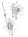
- Fig. 1 shows a portable cordless antenna 10 adapted for mounting on the side window 12 of a motor vehicle.
- Antenna 10 comprises an outer RF transfer member 14 which includes a weather-resistant carrier formed of suitable plastic material having an electrically conductive plate 17 on its underside. In this manner, when outer RF transfer member 14 is positioned on the window 12 as illustrated in Figures 1 and 2, electrically conductive plate 17 will be engagement with the outside of window 12.
- Antenna 10 includes a radiator 16 having a loading coil 18 with its proximal end 19 connected by suitable electrically conductive connection means to conductive plate 17.
- suitable electrically conductive connection means to conductive plate 17.
- Outside radiator 16 is intended to be located on the outside of the side window of the vehicle, and to extend substantially vertically upward for optimum reception from cellular sites which generally radiate in a manner that a vertically upward antenna provides optimum reception.
- Antenna 10 also comprises an inner RF transfer member 20 which includes a base 22 formed of a suitable plastic material and which carries a second electrically conductive plate (not shown) on its underside. When the inner transfer member 20 engages the inside of window 12, the second electrically conductive plate will be engagement with the inside of window 12.
- An inside radiator 24 is pivotally connected to inner RF transfer member 20 by means of a movable clutch 26.
- Movable clutch 26 is constructed so as to electrically connect radiator 24 to the second electrically conductive plate which is on the underside of RF transfer member 20 and which engages the inside of window 12. In this manner, inside radiator 24 will pick up the signal from a hand held cellular phone and will act as a repeater to aid in transferring the energy from the hand held cellular phone located within the car, through window 12 to outside antenna 16.
- outside antenna 16 be mounted substantially vertically which enables it to obtain the best match to the cell site.
- the inside antenna 24 should be pivoted so as to be parallel with the hand held cellular phone inside the car in order to obtain the maximum transfer of energy.
- the inside radiator 24 should be angled approximately as illustrated in Figure 1 and in full lines in Figure 6, extending downwardly and forwardly in the vehicle so as to be parallel to the antenna of the hand held cellular phone which is being used by the passenger.
- the cordless antenna 10 on the left front window, on the driver's side.
- Inside radiator 24 will then be pivoted to extend downwardly and forwardly with respect to the left window, as illustrated in dashed lines in Figure 6, approximately 90° from the angle shown in Figure 1. It has been found that extending inside antenna 24 at an angle of approximately 45° with respect to a vertical or horizontal plane, is satisfactory.
- Transfer members 14 and 20 each include a pair of opposed journal members 30,32, each of which defines a hole 33 for receiving a wire member.
- a pair of wire members 34,36 are provided with an end of each of the wire members extending into one of the holes 33, for enabling outer transfer member 14 and inner transfer member 20 to pivot about the axis of its holes 33, which holes have a common axis.
- outer transfer member 14 and inner transfer member 20 can be porta- bly connected to window 12 by placing the outer transfer member 14 and the inner transfer member 20 on opposite sides of the side window 12 and enabling wire members 34 and 36 to bridge the transfer members.
- Wire members 34 and 36 are formed of spring steel and have a resistency so as to urge outer transfer member 14 and inner transfer member 20 toward each other, to be clamped against window 12, thereby providing contact of the electrically conductive members carried by the underside of the transfer members to the opposite sides of the window 12. Since outer radiator 16 is electrically connected to electrically conductive member 17 and since inner radiator 24 is electrically connected to the electrical conductive member on the underside of inner transfer member 20, RF energy is transferred through the window 12. The invention enables a rapid and effective connection of the portable cordless antenna 10 to the side window of the vehicle.
- Movable clutch 26 is an adjustable clutch which includes a movable clutch housing 40 (Fig. 3) and a clutch stud 42 defining a threaded bore 44 into which a screw 46 extends to connect electrically conductive member 48 to the clutch housing.
- Clutch housing 40 and clutch stud 42 are formed of electrically conductive material with clutch housing 40 defining threaded recess 50 for receiving inside radiator 24. Inside radiator 24 is coated with a suitable plastic material.
- Movable clutch housing 40 defines a central opening 52 for receiving a spring 54 and a bolt 56.
- Bolt 56 extends through the spring into bore 44 and as bolt 56 is turned to compress spring 54, the tension of the movable clutch will increase.
- FIG 4 another embodiment is shown in which a more permanent antenna 10' is mounted to the window by a suitable adhesive, such as adhesive tape.
- a suitable adhesive such as adhesive tape.
- Outer RF transfer member 14' with electrically conductive member 17 on its underside, is affixed to window 12 by means of adhesive tape 60.
- Inner RF transfer 20' with electrically conductive member 48 on its underside, is affixed to the inside of the vehicle's window 12 by means of adhesive tape 62.
- the various structural components of antenna 10' are similar to the structural components of antenna 10, except that antenna 10' is affixed to window 12 by means of adhesive instead of being clamped onto the window as illustrated with respect to Figures 1 and 2.
Landscapes
- Engineering & Computer Science (AREA)
- Remote Sensing (AREA)
- Support Of Aerials (AREA)
- Details Of Aerials (AREA)
Applications Claiming Priority (2)
| Application Number | Priority Date | Filing Date | Title |
|---|---|---|---|
| US550324 | 1983-11-09 | ||
| US07/550,324 US5059971A (en) | 1990-07-09 | 1990-07-09 | Cordless antenna |
Publications (1)
| Publication Number | Publication Date |
|---|---|
| EP0468615A1 true EP0468615A1 (de) | 1992-01-29 |
Family
ID=24196696
Family Applications (1)
| Application Number | Title | Priority Date | Filing Date |
|---|---|---|---|
| EP91302914A Withdrawn EP0468615A1 (de) | 1990-07-09 | 1991-04-03 | Schnurlose Antenne |
Country Status (3)
| Country | Link |
|---|---|
| US (1) | US5059971A (de) |
| EP (1) | EP0468615A1 (de) |
| JP (1) | JPH04233803A (de) |
Families Citing this family (14)
| Publication number | Priority date | Publication date | Assignee | Title |
|---|---|---|---|---|
| ES2037607B1 (es) * | 1991-11-29 | 1996-08-01 | Dik Plasticos Sa | Base para antenas. |
| US5742255A (en) * | 1994-07-12 | 1998-04-21 | Maxrad, Inc. | Aperture fed antenna assembly for coupling RF energy to a vertical radiator |
| US5451966A (en) * | 1994-09-23 | 1995-09-19 | The Antenna Company | Ultra-high frequency, slot coupled, low-cost antenna system |
| US5600333A (en) * | 1995-01-26 | 1997-02-04 | Larsen Electronics, Inc. | Active repeater antenna assembly |
| US5596316A (en) * | 1995-03-29 | 1997-01-21 | Prince Corporation | Passive visor antenna |
| US6172651B1 (en) | 1995-10-25 | 2001-01-09 | Larsen Electronics, Inc. | Dual-band window mounted antenna system for mobile communications |
| US5898408A (en) * | 1995-10-25 | 1999-04-27 | Larsen Electronics, Inc. | Window mounted mobile antenna system using annular ring aperture coupling |
| US5990840A (en) * | 1997-03-11 | 1999-11-23 | Auden Technology Mfg. Co., Ltd. | Signal receiving gain device for car mobile-phones |
| US20040002792A1 (en) * | 2002-06-28 | 2004-01-01 | Encelium Technologies Inc. | Lighting energy management system and method |
| US8462062B2 (en) * | 2006-05-12 | 2013-06-11 | Solstice Medical, Llc | RF passive repeater for a metal container |
| US8264347B2 (en) * | 2008-06-24 | 2012-09-11 | Trelleborg Sealing Solutions Us, Inc. | Seal system in situ lifetime measurement |
| US8289217B2 (en) * | 2010-06-04 | 2012-10-16 | GM Global Technology Operations LLC | In-vehicle antenna system and method |
| US8525746B2 (en) * | 2010-06-04 | 2013-09-03 | Gm Global Technology Operations, Llc | In-vehicle antenna system and method |
| WO2015133276A1 (ja) * | 2014-03-04 | 2015-09-11 | 旭硝子株式会社 | ガラスアンテナ及びアンテナを備える窓ガラス |
Citations (2)
| Publication number | Priority date | Publication date | Assignee | Title |
|---|---|---|---|---|
| EP0330780A2 (de) * | 1988-03-04 | 1989-09-06 | Herbert Rudolph Blaese | Tragbare Antenne |
| EP0431640A2 (de) * | 1989-12-08 | 1991-06-12 | Larsen Electronics, Inc. | Antennensystem für zellulares Mobilfunksystem |
Family Cites Families (3)
| Publication number | Priority date | Publication date | Assignee | Title |
|---|---|---|---|---|
| DE3205750C2 (de) * | 1982-02-18 | 1990-03-29 | Hans Kolbe & Co, 3202 Bad Salzdetfurth | Biegestück für einen Antennenstab einer Kfz-Antenne |
| DE3537107A1 (de) * | 1985-10-18 | 1987-04-23 | Licentia Gmbh | Funkuebertragungsanordnung an empfaenger in fahrzeuginnenraeume |
| JPS6436128A (en) * | 1987-07-30 | 1989-02-07 | Miharu Communication | Method for receiving fm broadcast in mobile body |
-
1990
- 1990-07-09 US US07/550,324 patent/US5059971A/en not_active Expired - Fee Related
-
1991
- 1991-04-03 EP EP91302914A patent/EP0468615A1/de not_active Withdrawn
- 1991-05-31 JP JP3157594A patent/JPH04233803A/ja active Pending
Patent Citations (2)
| Publication number | Priority date | Publication date | Assignee | Title |
|---|---|---|---|---|
| EP0330780A2 (de) * | 1988-03-04 | 1989-09-06 | Herbert Rudolph Blaese | Tragbare Antenne |
| EP0431640A2 (de) * | 1989-12-08 | 1991-06-12 | Larsen Electronics, Inc. | Antennensystem für zellulares Mobilfunksystem |
Also Published As
| Publication number | Publication date |
|---|---|
| JPH04233803A (ja) | 1992-08-21 |
| US5059971A (en) | 1991-10-22 |
Similar Documents
| Publication | Publication Date | Title |
|---|---|---|
| US5059971A (en) | Cordless antenna | |
| CA1262562A (en) | Portable radio | |
| US6112106A (en) | Antenna transmission coupling arrangement | |
| US4661992A (en) | Switchless external antenna connector for portable radios | |
| US5642402A (en) | Hands free equipment | |
| US5828341A (en) | Laptop computer having internal radio with interchangeable antenna features | |
| GB2266997A (en) | Radio antenna. | |
| US5493702A (en) | Antenna transmission coupling arrangement | |
| US5440315A (en) | Antenna apparatus for capacitively coupling an antenna ground plane to a moveable antenna | |
| EP0550122B1 (de) | Hilfsantenne | |
| US20060176225A1 (en) | Antenna arrangement for connecting an external device to a radio device | |
| EP0862239A1 (de) | Mehrfrequenz-antenne | |
| US6295033B1 (en) | Vehicle antenna assembly for receiving satellite broadcast signals | |
| JPS61269403A (ja) | アンテナ | |
| MXPA97009334A (es) | Acoplador de antena para un radiotelefono portatil | |
| JPS6485431A (en) | Radio telephone system | |
| JPH08265024A (ja) | アンテナアセンブリ、アクティブ中継器アセンブリ及び信号伝送方法 | |
| US5181043A (en) | Passive repeater for cellular phones | |
| JPH01229501A (ja) | 携帯用アンテナ | |
| US5438338A (en) | Glass mounted antenna | |
| EP1091445A3 (de) | Antennenanordnung und Kommunikationssystem | |
| EP1056220A3 (de) | Mobiles Kommunikationsendgerät | |
| US5298907A (en) | Balanced polarization diversified cellular antenna | |
| US5999801A (en) | Wireless rechargeable CB microphone | |
| US5023622A (en) | On-glass antenna with center-fed dipole operation |
Legal Events
| Date | Code | Title | Description |
|---|---|---|---|
| PUAI | Public reference made under article 153(3) epc to a published international application that has entered the european phase |
Free format text: ORIGINAL CODE: 0009012 |
|
| AK | Designated contracting states |
Kind code of ref document: A1 Designated state(s): AT BE CH DE DK ES FR GB GR IT LI NL SE |
|
| 17P | Request for examination filed |
Effective date: 19920619 |
|
| 17Q | First examination report despatched |
Effective date: 19940103 |
|
| STAA | Information on the status of an ep patent application or granted ep patent |
Free format text: STATUS: THE APPLICATION IS DEEMED TO BE WITHDRAWN |
|
| 18D | Application deemed to be withdrawn |
Effective date: 19940625 |