EP0473385A1 - One-main-pipe type centralized lubrication apparatus - Google Patents
One-main-pipe type centralized lubrication apparatus Download PDFInfo
- Publication number
- EP0473385A1 EP0473385A1 EP91307811A EP91307811A EP0473385A1 EP 0473385 A1 EP0473385 A1 EP 0473385A1 EP 91307811 A EP91307811 A EP 91307811A EP 91307811 A EP91307811 A EP 91307811A EP 0473385 A1 EP0473385 A1 EP 0473385A1
- Authority
- EP
- European Patent Office
- Prior art keywords
- passage
- valve
- communicating
- oil
- cylinder bore
- Prior art date
- Legal status (The legal status is an assumption and is not a legal conclusion. Google has not performed a legal analysis and makes no representation as to the accuracy of the status listed.)
- Granted
Links
- 238000005461 lubrication Methods 0.000 title claims abstract description 30
- 238000003780 insertion Methods 0.000 claims description 28
- 230000037431 insertion Effects 0.000 claims description 28
- 238000010276 construction Methods 0.000 claims description 17
- 238000012856 packing Methods 0.000 claims description 17
- 238000001514 detection method Methods 0.000 claims description 15
- 230000007246 mechanism Effects 0.000 claims description 8
- 238000005520 cutting process Methods 0.000 claims description 3
- 238000005192 partition Methods 0.000 claims description 3
- 230000001105 regulatory effect Effects 0.000 claims description 3
- 230000004044 response Effects 0.000 claims description 3
- 230000000717 retained effect Effects 0.000 claims 1
- 239000003921 oil Substances 0.000 description 159
- 239000010687 lubricating oil Substances 0.000 description 50
- 238000004891 communication Methods 0.000 description 7
- 238000003754 machining Methods 0.000 description 7
- 230000001050 lubricating effect Effects 0.000 description 6
- 238000007789 sealing Methods 0.000 description 5
- 230000005284 excitation Effects 0.000 description 4
- 230000007935 neutral effect Effects 0.000 description 3
- 229920003002 synthetic resin Polymers 0.000 description 3
- 239000000057 synthetic resin Substances 0.000 description 3
- 230000005856 abnormality Effects 0.000 description 2
- 230000010354 integration Effects 0.000 description 2
- 101710129170 Extensin Proteins 0.000 description 1
- 230000009471 action Effects 0.000 description 1
- 230000001276 controlling effect Effects 0.000 description 1
- 230000008878 coupling Effects 0.000 description 1
- 238000010168 coupling process Methods 0.000 description 1
- 238000005859 coupling reaction Methods 0.000 description 1
- 238000010586 diagram Methods 0.000 description 1
- 238000007599 discharging Methods 0.000 description 1
- 238000009826 distribution Methods 0.000 description 1
- 239000004519 grease Substances 0.000 description 1
- 239000000314 lubricant Substances 0.000 description 1
- 239000010721 machine oil Substances 0.000 description 1
- 238000004519 manufacturing process Methods 0.000 description 1
- 238000000034 method Methods 0.000 description 1
- 238000003825 pressing Methods 0.000 description 1
- 230000008569 process Effects 0.000 description 1
Images






Classifications
-
- F—MECHANICAL ENGINEERING; LIGHTING; HEATING; WEAPONS; BLASTING
- F16—ENGINEERING ELEMENTS AND UNITS; GENERAL MEASURES FOR PRODUCING AND MAINTAINING EFFECTIVE FUNCTIONING OF MACHINES OR INSTALLATIONS; THERMAL INSULATION IN GENERAL
- F16N—LUBRICATING
- F16N7/00—Arrangements for supplying oil or unspecified lubricant from a stationary reservoir or the equivalent in or on the machine or member to be lubricated
- F16N7/38—Arrangements for supplying oil or unspecified lubricant from a stationary reservoir or the equivalent in or on the machine or member to be lubricated with a separate pump; Central lubrication systems
- F16N7/385—Central lubrication systems
-
- F—MECHANICAL ENGINEERING; LIGHTING; HEATING; WEAPONS; BLASTING
- F16—ENGINEERING ELEMENTS AND UNITS; GENERAL MEASURES FOR PRODUCING AND MAINTAINING EFFECTIVE FUNCTIONING OF MACHINES OR INSTALLATIONS; THERMAL INSULATION IN GENERAL
- F16N—LUBRICATING
- F16N13/00—Lubricating-pumps
- F16N13/02—Lubricating-pumps with reciprocating piston
-
- F—MECHANICAL ENGINEERING; LIGHTING; HEATING; WEAPONS; BLASTING
- F16—ENGINEERING ELEMENTS AND UNITS; GENERAL MEASURES FOR PRODUCING AND MAINTAINING EFFECTIVE FUNCTIONING OF MACHINES OR INSTALLATIONS; THERMAL INSULATION IN GENERAL
- F16N—LUBRICATING
- F16N13/00—Lubricating-pumps
- F16N13/02—Lubricating-pumps with reciprocating piston
- F16N13/06—Actuation of lubricating-pumps
- F16N2013/063—Actuation of lubricating-pumps with electrical drive
-
- F—MECHANICAL ENGINEERING; LIGHTING; HEATING; WEAPONS; BLASTING
- F16—ENGINEERING ELEMENTS AND UNITS; GENERAL MEASURES FOR PRODUCING AND MAINTAINING EFFECTIVE FUNCTIONING OF MACHINES OR INSTALLATIONS; THERMAL INSULATION IN GENERAL
- F16N—LUBRICATING
- F16N2230/00—Signal processing
- F16N2230/10—Timing network
-
- F—MECHANICAL ENGINEERING; LIGHTING; HEATING; WEAPONS; BLASTING
- F16—ENGINEERING ELEMENTS AND UNITS; GENERAL MEASURES FOR PRODUCING AND MAINTAINING EFFECTIVE FUNCTIONING OF MACHINES OR INSTALLATIONS; THERMAL INSULATION IN GENERAL
- F16N—LUBRICATING
- F16N2250/00—Measuring
- F16N2250/04—Pressure
Definitions
- the present invention relates to a one-main-pipe type centralized lubrication apparatus which connects a plurality of distributors to one main oil feed pipe so that lubricating oil measured by each distributors is adapted to be supplied particularly but not exclusively to lubricating parts of a construction machine, such as a truck crane or power shovel.
- this kind of one-main-pipe type centralized lubrication apparatus as disclosed in, for example, the Japanese Utility Model Publication Gazette No. Sho 52-150 and shown in Fig.17, comprises; an electric-operated pump device provided with a pump element A communicating with a tank T in which lubricating oil is charged and a pilot-operated directional control valve B ; one main oil feed pipe F connected to a discharge port P of the electric operated pump device, and a plurality of distributors G connected to the main oil feed pipe F .
- the directional control valve B controlling the movement of a spool C having first and second lands a and b . and being provided at one axial side of the spool C with a spring D .
- a discharge passage H which communicates with the discharge side of the pump element A and with the discharge port P through the one main pipe, and a pilot passage I for communicating the pilot chamber E with the discharge passage H and a depressurized passage J for allowing the pilot chamber E to be open at the tank T through the spool C .
- Each distributor G is provided; with two first and second chambers L and M partitioned by a valve body K , the the first chamber L communicating with the main pipe F ;and with a measuring cylinder N having a measuring piston n selectively communicating with the respective chambers L and M following the movement of the valve K , the first chamber L communicating with the main pipe F is pressurized to move the valve K so as to discharge lubricating oil in the second chamber M toward the lubrication parts,lubricating oil supplied from the main pipe F is introduced into the cylinder N and measured thereby, and thereafter the main pipe F side is depressurized so that the valve K is restored by operation of a spring S and the lubricating oil measured by the cylinder N is supplied to the second chamber M by operation of measuring piston thereby preparing the next oil feed.
- the distributors are each provided with the measuring cylinder N disposed perpendicularly to the moving direction of the valve K , and improved distributors are proposed which dispose the valve and measuring piston in series so as to enable the valve body to be compact .
- Such distributor is disclosed in, for example, the U.S.P.
- a cylinder bore U communicating with an oil feed passage Q and an oil discharge passage R is formed in a valve body O having the oil feed passage Q and oil discharge passage R
- a measuring piston V is reciprocably provided in the cylinder bore U
- the cylinder bore U is partitioned into a measuring chamber e and a back chamber f by the piston V
- a valve W is disposed at the oil feed passage Q side of cylinder bore U
- a spring X is interposed between the valve W and the piston V
- in the valve body O is formed an oil passage Y extending from the oil feed passage Q to the back chamber f.
- the oil feed passage Q at each distributor constructed as the above-mentioned is connected to the main pipe communicating with a pump and lubricating oil is supplied to the oil feed passage Q by driving the pump, whereby the valve W at each distributor is forwardly moved to supply to the back chamber f at the cylinder bore U the lubricating oil supplied to the oil feed passage Q and the piston V is forwardly moved following the supply of lubricating oil, thereby feeding lubricating oil of a predetermined amount measured at the measuring chamber e from the oil discharge passage R to lubricating parts, such as a machinetool.
- the pump stops its drive to depressurize the main pipe connected with the oil feed passage Q .
- valve body W is backwardly moved to cut off the communication of oil feed passage Q with the oil passage Y , and simultaneously therewith the piston V is backwardly moved by the spring X so that the lubricating oil supplied to the back chamber f side is introduced into the measuring chamber e and measured therein for the next oil feed.
- the oil passage Y for communicating the oil feed passage Q with the back chamber f at the piston V forms a vertical passage at the lateral side of cylinder bore U at the valve body O and a horizontal passage for communicating the vertical passage with the oil feed passage Q and back chamber f , so that the passage machining is very complicated.
- the vertical and horizontal passages constituting the oil passage Y must perforate the outer surface of valve body O , whereby after the passage machining, a plug (not shown) must be mounted for closing each perforating portion.
- a main object of the present invention is to provide a one-main-pipe type centralized lubrication apparatus which, even when lubricating oil of high viscosity is used or the apparatus is used in low temperature condition, can ensure pressurization and depressurization with respect to a main oil feed pipe and reliably feed oil from distributors.
- Another object of the invention is to provide a distributor for a one-main-pipe type centralized lubrication apparatus easy to machine oil passages, easy to automatically assemble, and inexpensive to produce as a whole.
- a first characteristic of the present invention is that at a one-main-pipe type centralized lubrication apparatus comprising; a pump device having a motor,a pump element operable in association with the motor , a tank communicating with the suction side of the pump element, and an oil discharge passage communicating with the discharge side of the pump element; one main oil feed pipe connected to the discharge side of the pump device; one oil feed pipe connected to the main oil feed pipe; and a plurality of distributors connected to the main oil feed pipe; the pump device being constructed as follows :
- the pump device is provided with a depressurization passage for opening the discharge passage at the tank and a de pressurization valve for opening or closing the depressurization passage with respect to the tank, the motor being normally and reversely rotatable, and between the motor and the depressurization valve is provided an interlocking mechanism which, when the motor normally rotates, controls the depressurization valve to be closed and, when the same reversely rotates. controls the depressurization valve to be open.
- the pump element operates following the normal rotation of the motor so that the lubricating oil in the tank is supplied from the discharge passage at the pump body to the distributors and after the lubricating oil of predetermined amount is supplied to the distributors and oil feed therefrom is completed, the motor is reversely rotates so that the depressurization valve operates to forcibly open toward the tank the depressurization passage housing therein the depressurization valve, whereby the discharge passage, that is, the main pipe is immediately depressurized.
- the interlocking mechanism is provided with an interlocking member moving in reciprocation between a first position of closing the depressurization valve and a second position for opening the same in association with the normal and reverse rotations of motor and between the interlocking member and the depressurization valve is provided an elastic member which, when the interlocking member is put in the first position, biases the depressurization valve in the closing direction and, when pressure of the discharge passage exceeds a predetermined pressure, biases the depressurization valve to be open.
- valve body is retracted by the reverse rotation of motor to open the depressurization passage so as to immediately perform depressurization.
- the valve body operates to open the discharge passage, so that the depressurization valve serves also as a safety valve, thereby being superior in safety.
- the pump device comprises a first communicating passage for communicating the pressurization passage with the discharge passage, a second communicating passage for communicating with the tank, and a valve chamber in which the respective communicating passages are open,
- the depressurization valve comprises a spool for communicating with or shutting off each communicating passage, so that the spool may be reciprocably housed in the valve chamber, and provided withs a position control member position-controlled to the first position where the respective communicating passages are cut off and the second position where the same are communicated in association with the normal and reverse rotations of motor.
- a discharge pressure detection passage communicating with the discharge passage, an indicator housed in the detection passage to operate in response to a rise in discharge pressure, a sensor for detecting operation of the indicator, and for giving a reverse rotation command to the motor on a basis of the detection result of sensor.
- a short wiring path can give a reverse rotation command to the motor with accuracy in comparison with the case where the rise in discharge pressure when oil feed is completed is detected at the distributor side to give the reverse rotation command to the motor.
- a motor control circuit for reversely rotating the motor by turning on a depressurization detection sensor for detecting the depressurization pressure and for stopping the motor by turning off the same, is provided to facilitate the normal and reverse rotation control of the motor.
- a second characteristic of the present invention is construction of the distributors at the one-main-pipe type centralized lubrication apparatus.
- the distributors are each provided with a valve body having a cylinder bore in which the oil feed passage and oil discharge passage connected to the main oil feed pipe are open, a measuring piston movably housed in the cylinder bore so as to partition the cylinder bore into a measuring chamber and a back chamber, a valve for switching the back chamber of measuring piston to one of the oil feed passage and measuring chamber, and a spring interposed between the valve and the measuring piston so as to bias the valve and measuring piston in the direction of moving away from each other, and further has the following construction :
- the sleeve is fitted into the cylinder bore so that the oil passage can be formed of the sleeve and open groove, the open groove being merely formed lengthwise of the cylinder bore, whereby the oil passage can simply be formed without the conventional passage machining.
- the passage block having the communicating bore so that the oil passage is communicated with the oil feed passage through the communicating bore, in other wards, the communicating bore need only be formed at the passage block and the horizontal passage as in the conventional example need not be formed at the valve body, thereby facilitating machining of the passage.
- the bottom surface around the opening at which the oil feed passage is open is provided, and the other lengthwise end is open, so that fixing means for fixedly pressing to the bottom surface the passage block and sleeve fitted into the valve body from the opening side of cylinder bore is used, which is one characteristic of the invention.
- the passage block, sleeve, valve , spring and measuring piston can be assembled from the opening side of cylinder bore and the passage block and sleeve fitted into the cylinder bore from the opening side thereof are pressed onto the bottom surface, thereby being fixed into the cylinder bore.
- the respective parts can simply be assembled and automatic assembly also is easy.
- the cylinder bore and sleeve fitted therein are tapered at the oil feed passage sides thereof toward the oil feed passage.
- sealing efficiency between the oil discharge passage and the oil passage is good so as to prevent lubricating oil from leaking from the oil passage to the oil discharge passage.
- an oil discharge bore coincident with the oil discharge passage at the valve main body and a positioning projection for the oil discharge bore and engageable with the open groove.
- the passage block coomprises a passage member having the communicating bore and an end member facing the measuring chamber,the passage member and end member having insertion bores into which the valve body is movably fitted, the end member being provided with a first packing facing the insertion bore and contacting with the surface of passage member, and the valve body being provided with a second packing facing the oil feed passage and contacting with the rear surface of passage member.
- the end member may be integral with the sleeve.
- the sleeve may be straight cylindrical and be formed of a single member and alternatively formed of two members of a first sleeve to hold the passage block and a second sleeve having a regulating portion to regulate movement of the measuring piston so that the sleeves may be inserted into the cylinder bore in an abutting manner.
- At the first sleeve is provided an open groove extending lengthwise of the cylinder bore and open therein so that an oil passage for commnnicating the oil feed passage with the rear chamber of the measurinf piston is formed when the first sleeve together with the second sleeve is inserted into the cylinder bore.
- the passage is further simple to form and the main valve body need only be provided with the cylinder bore, oil feed passage and oil discharge passage, thereby enabling its workability to be improved and the first and second sleeves are molded of synthetic resin, thereby further improving the workability.
- a one-main-pipe type centralized lubrication apparatus shown in Fig.1 comprises an electric-operated pump device 100 and a plurality of distributors 300 connected to the electric-operated pump device 100 through one main oil feed pipe 200.
- the electric-operated pump device 100 disposes in a pump body 1 a pump element 3 operable in association with a motor 2, forms at the suction side of the pump element 3 of the pump body 1 a suction passage 5 communicating with a tank 4 charged with lubricating oil, and is provided at the discharge side of pump element 3 of the pump body 1 with a discharge passage 6 connected with the main pipe 200.
- the pump element 3 is provided with a cylinder chamber 7 communicating with the suction passage 5 and a piston 8 reciprocably provided in the cylinder chamber 7, the piston 8 being connected to the foremost end of a crank 11 fitted into an eccentric cam 10 fixed to a rotary shaft 9 of the motor 2, and the piston 8 is moved in reciprocation in the cylinder chamber 7 through the crank 11 following the rotation of motor 2, whereby the lubricating oil taken-in into the cylinder chamber 7 from the tank 4 into the cylinder chamber 7 through a suction passage 5 is forced to be supplied to the discharge passage 6 and a discharge valve 12 interposed therein is open against a spring 12a , thereby supplying the lubricating oil from the discharge passage 6 to the main pipe 200 through the open discharge valve 12.
- Each distributor 300 is so constructed that in a valve body 13 are formed a plurality of cylinder bores 14 communicating with the main pipe 200, a measuring piston 15 is reciprocably provided in each cylinder bore 14, a valve 16 is provided at the communication side of cylinder bore 14 with the main pipe 200, a spring 17 is interposed between the valve 16 and the piston 15, in the valve body 13 is formed an oil passage 18 for the lubricating oil, extending the from the connection side of cylinder bore 14 with the main pipe 200 near the valve 16 toward a rear chamber 15a of the measuring piston 15 in the cylinder bore 14 and at the valve body 13 is formed a discharge passage 19 extending from an intermediate portion in the reciprocation direction of the piston 15 toward the outside of valve body 13.
- each valve 16 has a communicating passage 16a which, during the depressurization to be discussed below, and communicates the oil passage 18 with a measuring chamber 20 provided between the measuring piston 15 and the valve 16.
- valve 16 backwardly moves (lower) by depressurization to be discussed below, and the piston 15 backwardly moves (rises) by being biased by the spring 17, so that the lubricating oil introduced into the back chamber 15a of piston 15 is introduced into the measuring chamber 20 at the cylinder bore 14 through the oil passage 18 and communicating passage 16a provided at the valve 16, thereby preparing for the next oil feed.
- reference numeral 21 designates a control box housing therein a control circuit 22 for the motor 2 to be discussed below.
- the electric-operated pump 100 is so constructed that within the pump body 1 is formed a depressurization passage 23 for opening the discharge passage 6 at the tank 4 side through the suction passage 5, a pressurization valve 24 is interposed in the pressurization passage 23, a normally and reversely rotatable motor is used as the motor 2, and the depressurization valve is open in association with the reverse rotation of motor 2, so that the depressurization valve 24 is open to carry out depressurization of the main pipe 200 communicating with each distributor 300.
- the depressurization valve 24 shown in Figs.1 through 4 comprises a spherical valve 25 disposed at the opening side of the depressurization passage 23 toward the discharge passage 6, an interlocking member 26 reciprocable in association with the normal and reverse rotations of motor 2, and an elastic member 27 interposed between the valve 25 and the interlocking member 26, the interlocking member 26 retracting to open the valve 25 which is always biased in the closing direction by the elastic member 27, thereby performing depressurization. Also, in the above-mentioned construction, when pressure at the discharge passage 6 becomes abnormally high by a failure in each distributor, the valve 25 is open by the high pressure against the elastic member 27 so that the high pressure at the discharge passage 6 can be released to the tank 4, thus the valve 25 is formed both as a safety valve.
- an eccentric cam plate 28 which is integrally rotatably mounted to a rotary shaft 9 of motor 2 and having an operating pin 28a projecting from the outer periphery of the cam plate 28 and a sliding member 29 which is supported to the interlocking member 26 in relation of being movable within a predetermined range and has a projection projecting from the opposite surface to the pin 28a , are used, so that the operating pin 28a at the eccentric plate 28 is allowed to abut against the projection 29a at the sliding member 29 following the normal or reverse rotation of motor 2, whereby the sliding member 29 is moved in reciprocation to move the interlocking member 26 toward a first position where the valve 25 closes the opening of depressurization passage 23 toward the discharge passage 6 and a second position where the valve 25 is positioned inwardly of depressurization passage 23 apart from the opening so as to depressurize the distributors 300.
- interlocking member 26 At the outer periphery of interlocking member 26 are provided two engaging grooves 30 and 31 spaced from each other at a predetermined interval, and a detent mechanism is provided which comprises the engaging grooves 30 and 31 andan engaging member 32 elastically engageable with one of the engaging grooves 30 and 31 and composed mainly of a ball, so that the interlocking member 26 is capable of being held inthe first or the second position.
- first and second springs 33 and 34 for holding the sliding member 29 at a neutral position in the sliding direction, so that, when the motor 2 is normally rotatably driven, the sliding member 29 is moved against the first spring 33 so as to hold the interlocking member 26 in the first position by the detent mechanism.
- the sliding member 29 moves in reciprocation, but returns to the neutral position by a spring force of the first spring 33.
- the motor 2 is reversely rotated, the operating pin 28a abuts against the projection 29a of sliding member 29, the sliding member 29 moves against the second spring 34, the interlocking member 26 is held in the second position by the detent mechanism , and thereafter the sliding member 29, as the same as during the normal rotation, can return to the neutral position.
- FIG.1 through 4 An embodiment shown in Fig.1 through 4 is provided at the pump body 1 with a discharge pressure detection passage 35 communicating with the discharge passage 6, in the discharge pressure detection passage 35 is housed an indicator 36 movable when the discharge pressure at the discharge passage 6 rises, and on the moving path of the indicator 36 is disposed a sensor 37 comprising a limit switch, so that, when the discharge pressure at the discharge passage 6 rises, a reverse rotation command is given from the senso 37 toward the motor 2.
- the motor 2 When the lubricating oil is intended to be supplied from the electric-operated pump 100 to the distributors 300, as shown in Fig.2, the motor 2 is normally rotated, so that the the interlocking member 26 of depressurization valve 24 moves in association with the motor 2 to put the valve 25 in the first position where the valve 25 closes the depressurization passage 23.
- the pump element 3 is actuated following the normal rotation of motor 2 so as to supply the lubricting oil in the tank 4 from the discharge passage 6 at the pump body 1 to the distributors 300 through the main pipe 100.
- the predetermined amount of lubricating oil is supplied to the distributors 300 to complete oil fedd thereat and pressure in the main pipe 200 rises, as shown in Fig.
- the motor 2 is reversely rotated to actuate the depressurization valve 24 to thereby forcibly depressurizing the main pipe 200, so that, even when lubricating oil of high viscosity is used or the apparataus is used in low temperature condition,depressurization can be quickly performed, thereby exactly operating the distributors 300.
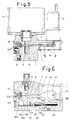
- the depressurization valne 24, as shown in Figs.5 and 6, may use a directional valve of a spool type for selectively changing-over supply of lubricating oil to the distributors 300 and depressuriztion thereof.
- the depressurization valve 24A shown in Fig.6 uses a spool 38 having two first and second lands 38a and 38b and provided therebetween with a smaller diameter portion 38c , the spool 38 is connected through a connecting pin 40 with a position control member 39 for the spool 38, which reciprocates in association with the rotary shaft 9 of motor 2, and the position control member 39 is moved in reciprocation by the normal and reverse rotations of motor 2, thereby changing over the spool 38.
- an engaging groove 39a extending lengthwise thereof, and a projection 42a engageable with the engaging grove 39a at the position control member 39 is integrally formed at a lateral portion of the crank 42 fitted onto an eccentric cam 41 fixed to the rotary shaft 9 of motor 2 and connected at the utmost end with the piston 8 of pump element 3.
- a spring 43 and two lift-prevention pins 44 are formed within the pump body 1 and at both opposite sides thereof, whereby the position control member 39 is supported by the spring 43 and pins 44.
- the spool 38 is reciprocably housed in a valve chamber 45 provided at the pump body 1, and in the valve chamber 45 are open a first communicating passage 6a communicating with the discharge passage 6 and a second communicating passage 5a communicating with the tank 4 through the suction passage 5, the first and second communicating passage 6a and 6a and valve chamber 45 constituting a depressurization passage.
- the position control member 39 is moved in the reverse direction (rightwardly) to the position in Fig.6 and the first land 38a of spool 38 closes the openings of the first and second communicating passages 6a and 5a so that the spool 38 is controlled to be in the first position where the communicating passages 6a and 5a cut off communication therebetween, thereby eliminating the depressurization.
- the lubricating oil supplied from the discharge passage 6 to the distributors 300 through the main pipe 200 in Fig.6, an O-ring 46 is provided at the outer periphery of the second land 38b so that the spool 38 can be held at its moving position by the O-ring 46.
- the motor 2 is preferable to use a normally and reversely rotatable DC motor.
- the normal and reverse rotation control for the motor 2 is carried out by a motor control circuit 22 using a depressurization sensor shown in Fig. 7.
- control circuit 22 in Fig. 7 interposes in a power supply line connected to a DC power source, such as a battery, a key switch KS which is on in association with turn-on of an operation switch at a main machine of an oil feed object, for example, a power shovel, and an instantaneous contact 62G-1 at a signal timer 62G to be discussed below; connects to the power supply line a system timer 2G which integrates an operation time of the main machine and outputs an oil feed command every predetermined time; between the power supply lines are connected in parallel an integration auxiliary relay 16GX which is energized by turn-on of the key switch KS to issue an integration instruction to the system timer 2G and a series circuit of a contact 33G of the limit switch 37 operating by the operation of indicator 36 and constituting the depressurization detection sensor and an on-delay relay DL excited after the turn-on of contact 33G , at a delay of, for example, 5 through 10 seconds.
- a key switch KS which is
- reference numeral 33GX2-2 designates a normally closed contact at the operation auxiliary relay 33GX2
- 16GX-1 designates a normally closed contact of the auxiliary relay 16GX .
- the key switch KS is on so as to excite the auxiliary relay 16GX
- the system timer 2G integrates the on-operation time of key switch KS
- the oil feed command is given every predetermined time.
- the system timer 2G is on to close its contact 2G-1 , whereby the operation auxiliary relays 33GX1 and 33GX2 are excited to switch the contacts 33GX1-2 and 33GX2-1 thereof, a current flows in the motor 2 as shown by the solid line arrow in Fig.7, the motor 2 is normally rotated, and the lubricating oil is supplied to the distributors 300.
- the auxiliary relay 33GX11 is excited to turn on its normally open contact 33GX1-1 , then the self holding acts to continue the drive of motor 2.
- the contact 33G of limit switch 37 is on and the delay relay DL is excited, so that the normally closed contact DL-2 thereof is open after a predetermined time (5 through 10 sec.)
- the auxiliary relays 33GX1 and 33GX2 are released of excitation to switch contacts 33GX1-2 and 33GX2 -1 thereof, and a current flows in the motor 2 as shown by the dotted line arrow in Fig.7 through the normally open contact DL-1 to be closed by excitation of the on-delay relay DL , threby reversely rotating the motor 2.
- the main pipe 200 communicating with the distributors 300 is depressurized.
- the depressurization is further carried out, and, when the contact 33G of limit switch 37 is off, the on-delay relay DL is released of its excitation to stop energization of the motor 2.
- the signal timer 62G is operated following the excitation of auxiliary relay 33GX1 , and when counting by the signal timer 62G for a predetermined time is completed, the off-operation of contact at the timer 62G stops the motor 2.
- the electric-operated pump 100 is provided within the pump body 1 with a depressurization passage 23 for opening the discharge passage 6 toward the tank 4, the motor 2 for driving the pump element 3 is made normally and reversely rotatable, depressurization valves 24 and 24A operable in association with the reverse rotation of motor 2, and the depressurization valves 24 and 24A are housed in the depressurization passage 23, whereby the motor 2 reversely rotates to actuate the depressurization valves 24 and 24A so as to force the discharge passage 6 communicating with the distributor, in turn the main pipe, to be depressurized. Accordingly, even when the lubricating oil of high viscosity is used or the apparatus is used in low temperature condition, the depressurization is quick and accurate operation at the distributors is carried out, thereby enabling exact oil feed to be caried out.
- the depressurization valve 24, as shown in Figs.1 through 4, comprises the valve 25, the interlocking member 26 movable in reciprocation in association with the normal and reverse rotations of motor 2, and the elastic member 27 interposed between the valve 25 and the interlocking member 26 so as to bias the valve 25 in the closing direction and to open the valve 25 when pressure at the discharge passage 6 is abnormally high, whereby the depressurization is quickly carried out and, when a failure is caused in the distributor or the like, the depressurization valve 24 is usable also as a safety valve, thereby being superior in safety.
- the depressure valve 24A comprises the spool 38, to which the position control member 39 movable in reciprocatin in association with the normal and reverse rotations of motor 2 is connected, whereby the change-over spool 38 changes-over the discharge passage 6 into the depressurization circuit 23 to enable further exact depressurization.
- the pump body 1 is provided with the discharge pressure detection passage 35 communicating with the discharge passage 6, the indicator 36 housed in the detection passage 35 and operable in response to the rise of discharge pressure, and the sensor 37 for detecting operation of indicator 36 to give a reverse rotation command to the motor 2, so that simple wiring can give the accurate reverse rotation command in comparison with construction to detect the rise of discharge presure when oil feed ends, and to give the same command to the motor 2.
- the motor 2 uses a normally and reversely rotatable DC motor and a motor control circuit 22 is provided which reverely rotates the motor 2 by on-operation of the depressurization detection sensor 37 for detecting the depressurization and to stop the rotation of motor 2 by off-operation of the same, whreby the motor 2 is easy to control its normal and reverse rotations and oil feed from the distributor is ensured.
- each distributor 300 connected to the electric-operated pump device 100 through the mainpipe 200 as the above-mentioned.
- a valve body 50 at a valve body 50 are formed four vertical cylinders bores 51 vertically extending, in each of which a measuring piston 52 is housed in relation of being movable in reciprocation, each cylinder bore 51 is partitioned therein into a measuring chamber 53and a back chamber 54, and at the valve body 50 are formed one oil feed passage 56 communicating with each cylinder bore 51 through a branch 55 so as to supply lubricating oil to each cylinder bore 51, and a plurality of oil discharge passage 57 for discharging the lubricating oil from each cylinder bore 51.
- a valve 58 is disposed at the oil feed passage 56 side of each cylinder bore 51 and a spring 59 is interposed between each valve 58 and each piston 52.
- Each cylinder bore 51 provided at the valve body 50 is open at the lengthwise upper side and blind at the lower side, at the valve 50 is provided an open groove 51a open to the cylinder bore 51 side and vertically extending along the cylinder bore 51, and a sleeve 60 is fitted into the cylinder bore 51, so that an oil passage 61 communicating with the back chamber 54 is formed between the sleeve 60 and the open groove 51a .
- a passage block 64 having a communicating bore 62 communicating with the oil passage 61 and an insertion bore 63 for insertably supporting the valve 58 in relation of being vertically movable, and at the valve 58 are formed first and second passages 65 and 66 for selectively communicating the communicating bore 62 at the passage block 64 with one of the oil feed passage 61 and measuring room 53 at the cylinder bore 51. Furthermore, at the upper opening of each cylinder bore 51 at the valve body 50 is fixed a lid 67 with a fixing bolt 68, so that the lid 67 fixedly assembles the sleeve 60 and passage block 64 within the valve body 50.
- the passage block 64 at first is fitted into each cylinder bore 51 from the upper opening side thereof at the valve body 50, into the insertion bore 63 at the block 64 is inserted the leg of valve 58, next, into the cylinder bore 51 are fitted the sleeve 60 and then the spring 59 and measuring piston 52, and thereafter the lid 67 is fixed onto the upper opening of cylinder bore 51 by the fixing bolt 68a , whereby the passage block 64 is pressed onto the bottom surface of cylinder bore 51 through the sleeve 60.
- the sleeve 60 and passage block 64 are simply fixedly assembled in the cylinder bore 51, thereby enabling simple assembly.
- valve body 50 since within the valve body 50 is formed an open groove 51a extending along the cylinder bore 51 and the sleeve 60 is fitted into the cylinder bore 51 so as to form the oil passage 61 communicating with the back chamber 54 at the cylinder bore 51, the oil passage 61 can simply be formed without the need of complicated machining of passage.
- the oil passage 56 is connected to the main pipe 200 communicating with the electric-operated pump 100 and when the electric-operated pump 100 is driven to supply lubricating oil to the oil feed passage 61, the valve 58 moves upwardly in the cylinder bore 51 so that the lubricating oil in the oil feed pasage 56 is supplied from the oil passage 61 formed with the sleeve 60 and open groove 51a to the back chamber 54 of cylinder bore 51 through the first passage 65 provided at the valve 58 and the communicating bore 62 provided at the passage block 64, so that the measuring piston 52 forwardly moves against the spring 59 following the supply of lubricating oil and the lubricatig oil of the predetermined amount measured in the measuring chamber 53 is lubricated to each lubricating portion, such as a power shovel, from the discharge passage 57.
- each lubricating portion such as a power shovel
- the electric-operated pump 100 is stopped to depressurize the main pipe 200 communicating with the oil feed passage 56, whereby the valve 58 with restored to cut off communication of the oil feed passage 56 with the oil passage 61 and simultaneously the piston 52 is restored by the spring 59, so that the lubricating oil supplied to the back chamber 54 is introduced into the measuring chamber 53 from the oil passage 61 through the communication bore 62 at the passage block 64 and second passage 66 provided at the valve 58, thereby preparing the next oil feed.
- the cylinder bore 51 formed at the valve body 50 has at the upper opening side a slightly larger diameter than an outer diameter of sleeve 60 inserted into the cylinder bore 51 and at the lower closing side a tapered portion 51b gradually taperd toward the oil feed passage 56, and at the lower portion of sleeve 60 is formeda tapered portion 60a coincident with the tapered portion 51b .
- an insertion work of sleeve 60 into the cylinder bore 51 becomes easy and the taperd portions 51b and 60a are fixedly fitted in relation of slidably contacting with each other, whereby the sealing efficiency between the sleeve 60 and the cylinder bore 51 is good, thereby reliably preventing the lubricating oil from leaking from the oil passage 61 to the oil discharge passage 57.
- the sleeve 60 as shown in Fig.11, is provided at a vertically intermediate portion coincident with the oil discharge passage 57 at the valve body 50 with an oil discharge bore 60b so that the lubricating oil measured in the measuring chamber 53 at the cylinder bore 51 is adapted to be discharged toward the oil discharge passage 57.
- a substantially V-like shaped guide 51c is formed at the upper end of open groove 51a provided at the valve body 50, so that the sleeve 60 can easily engage with the open groove 51a .
- the passage block 64 itself may be composed of one member, but, as shown in the embodiments in Figs.8 through 10, may be divided into the passage member 64A having the communicating bore 62 and the end member 64B for receiving and supporting the sleeve 60, and may be fitted into the cylinder chamber 51 in the state where the end member 64B and passage member 64A are vertically layered.
- the laborious work such that packing 70 for sealing a gap between the insertion bore 63 at the passage block 64 and the valve 58 inserted into the insertion bore 63 is assembled therein at the passage block 64, is saved.
- the packing 70 can sequentially be assembled together with packing 71 for sealing a gap between the branch 55 of oil feed passage 56 at the valve body 50 and the valve 58 inserted therein and that between the lower surface of passage block 64 and the lower end face of cylinder bore 51.
- the passage member 64A and end member 64B are integral with each other, the laborious work that a packing housing chamber is provided on half way of the insertion bore 63 and the packing 70 is fitted into the housing chamber, is required, but when the passage member 64A and end member 64B are separate from each other, since the packing housing chamber can be formed at the end face of end member 64B , the mounting efficiency of packing 70 is improved to further facilitate the assembly.
- a window 67a is formed at a portion of lid 67 and an indicator is constructed to confirm through the window 67a the movement of piston 52.
- each distributor 300 is provided at the valve body 50 with the cylinder chamber 51 open at one length end and blind at the other lengthwise end and with the open groove 51a extending of cylinder bore 51, inserts the sleeve 60 into the cylinder bore 51 to form the oil passage 61 communicating with the back chamber 54 of cylinder bore 51, fits into the oil feed passage side of cylinderbore 51 the passage block 64 having the communicating bore 62 communicating with the oil passge 61 and the insertion bore 63 at the valve 58, fixes the sleeve 60 and passage block 64 to the valve body 50 by the lid 67 fixed thereto, and is provided at the valve 58 with passages 65 and 66 selectively communicating with one of the oil feed passage 56 and measuring chamber 53 at the cylinder bore 51, whereby the passages are easy to machine and the assembly of parts is easy and the manufacturing cost of the entire apparatus is low.
- the cylinder bore 51 and sleeve 60 are tapered at the oil feed passage 56 side thereof and toward the passage 56, thereby improving the sealing efficiency between the cylinder bore 51 and the sleeve 60 to reliably prevent the lubricating oil from leaking toward the oil discharge passage 57.
- the sleeve 60 is provided with an oil discharge bore 60b coincident with the oil discharge passage 57 at the valve body 50 and with a positioning projection 69 for the oil discharge bore 60b engageable with the open groove 51a , thereby ensuring the positioning of oil discharge bore 60b at the sleeve with respect to the oil discharge passage 57 and further facilitating assembly.
- the passage block 64 is composed of the passage member 64A having the communicating bore 62 and of the end member 64B facing the measuring chamber 53 at the cylinder bore 51, so that the packing 70 to be disposed at the insertion bore 63 side of valve body 58 and at the insertion bore 63 side of valve 58 can be saved of laborious work of previously assembing the packing 70 within the insertion bore 63.
- the packings 70 and 71 can sequentially be assembled with the passage member 64A and end member 64B when assembled in the cylinder bore 51, thereby further facilitating the assembly.
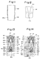
- the sleeve 60 is pipe-like-shaped and fitted into the cylinder bore 51 and the open groove 51a provided at the valve body 50 is closed so as to form the oil passage 61, but alternatively, as shown in Figs.13 and 14, the sleeve comprises a first sleeve 81 of synthetic resin mold having a holding portion 81a for holding a passage block 90 and a second sleeve 82 of synthetic resin mold having a restricting portion 82a for restricting the movement of measuring piston 83, the first and second sleeves 81 and 82 being fitted in an abutting manner in the cylinder bore 51, so that, as shown in Fig.14, the open groove 81b provided at one side outer surface of first sleeve 81 may be closed to form an oil passage 84.
- the first and second sleeves 81 and 82 form a valve unit member which can previously houses the measuring piston 83, a valve 91 to be discussed below and a spring 59.
- the valve unit member houses therein the above parts to form a valve unit of cartridge type and is adapted to be detachably fitted into the cylinder bore 51, thus the parts can previously be assembled in the valve unit member, whereby the parts can easily be exchanged and the valve 91 can be inspected of its operation prior to assembly with the valve body 50.
- the valve unit member is divided into the first and second sleeves 81 and 82, the measuring piston 83 for coupling the first and second sleeves 81 and 82 can easily be housed in the cylinder bore 51.
- the embodiment shown in Figs.13 and 14 forms an open groove 81b at one side wall of the first sleeve 81 and is provided at the cylinder bore 51 with a larger diameter portion 51d , so that the valve unit member formed of the first and second sleeves 81 and 82 is fitted into the cylinder bore 51, thereby forming the oil passage 84 for communicating the oil feed passage 56 with the back chamber 85 of the measuring piston 83.
- the first sleeve 81 provides an inner flange 81c at the opening side to the oil feed passage 56, in other words, at the lower portion of the same in Figs.13 and 14, so as to form a holding portion for a passage block 90, and at a lengthwise intermediate portion an oil discharge bore 81d communicating with the oil discharge passage 57 and further at the upperend a shoulder 81e .
- the second sleeve 82 is provided at the lower end thereof with a shoulder 82b engageable with the shoulder 81e at the first sleeve 81 and the shoulders 81e and 82b interpose therebetween an O-ring 86 so as to engage with each other in a abutting manner.
- the second sleeve 82 is provided at the upper portion thereof with a lid portion forming the restricting portion 82a and with a communicating bore 82c open at the back chamber 85 and for communicating the back chamber 85 with the oil passage 84, the lid portion having an adjusting screw bolt 87 screwably attached thereto so as to adjust movement of the measuring piston 83 and adjust an amount of lubricating oil discharged from the oil discharge passage 57.
- the passage block 90 is of construction corresponding to the passage member 64A at the embodiment shown in Figs.8 through 10, held to the holding portion 81a at the first sleeve 81 as enlargedly shown in Fig.15, provided with a communicating passage 90a communicating with the oil passage 84, and with an insertion bore 90b into which a valve 91 for communicating or cutting off the communicating passage 90a with respect to the oil feed passage 56 is movably fitted.
- the passage block 90 is provided at the end thereof with an end member 90c , which is held to the holding portion 81a of the first sleeve 81 and brought into press-contact with the bottom surface of cylinder bore 51 and fixed thereto.
- the passage block 90 is not essential, as communicating passage 90a and insertion bore 90b may be provided directly to the first sleeve 81.
- the valve unit member comprising the first and second sleeves 81 and 82, as shown in Figs.13 adn 14, retains to a shoulder provided at the outer periphery of the lid portion of second sleeve 82 a fixture 92 fixed to the opening side of the cylinder bore 51, whereby the first sleeve 81 is urged toward the bottom surface of cylinder bore 51 so as to bring the passage block 90 into press-contact with the bottom surface of cylinder bore 51 to be fixed thereto.
- the valve 91 operates as the same as the valve 58 in the embodiment shown in Figs.8 through 10, which comprises a short column-like-shaped valve 91a , a spring seat member 91b , and an entering portion 91c entering through a gap into the insertion bore 90b at the passage block 90 from an insertion bore 81f provided at the center of the inner flange 81c of the first sleeve 81, and in the embodiment shown in Figs.13 and 14, the valve 91a is separate from an upper valve 91d having the spring seat member 91b and entering member 91c .
- valve 91a and upper valve 91d both lift so that, when the valve 91d passes the communicating passage 90a at the passage block 90, the communicating passage 90a communicates with the oil feed passage 56 through the branch 55, the oil feed passage 56 communicating with the oil passage 84.
- the measuring piston 83 Since the lubricating oil is introduced through the above communication into the back chamber 85 of measuring piston 83, the measuring piston 83 lowers, so that the lubricating oil of the predetermined amount measured by the measuring chamber 53 is discharged from the oil discharge passage 57 and supplied to the predetermined lubricating parts. Also, when depressurized after oil feed is completed, the valve 91a and upper valve 91d both lower by operation of spring 59, when the upper valve 91d returns to the position shown in Figs.13 to 15, the oil passage 84 is cut off from the oil feed passage 56 and communicates with the measuring chamber 53 through the communicating passage 90a and a gap between the entering portion 91c and the insertion bores 81f and 90b . Also, the measuring piston 83 lifts by the action of spring 59 so that oil supplied to the back chamber 85 is introduced from the oil passage 84 to the measuring chamber 53 through the communicating passage 90a and the gap, thereby preparing for the next oil supply.
- valve 91 Since the valve 91 is formed as the above-mentioned, there is no need that the passage 66 is formed in the valve as shown by the valve 58 in the embodiment shown in Figs.8 through 10, thereby facilitating machining. Also, when the valve 91a is divided, the valve 91a is made simply columnar, workability thereof can further be simplified.
- FIGs.13 and 14 the components the same as those in Figs.8 through 10 are designated by the same reference numerals.
- Reference numeral 93 designates a cap mounted to the opening side of the cylinder bore 51.
- the above-mentioned distribution shown in Fig.13 through 15 can form the oil passage 84 by inserting the sleeves 81 and 82 into the cylinder bore 51 to form the oil passage 84, thereby facilitating the passage machining.
- the passage block 90 is provided, the communicating bore 90a only is provided at the passage block 90, so as to form a passage communicating with the oil passage 84 from the oil feed passage 56.
- the valve body 50 need only be provided with the cylinder bore 51, oil feed passage 56 and oil discharge passage 57, thereby improving the workability.
- the distributor shown in Figs.13 and 14 may be modified as shown in fig.16.
- a distributor shown in Fig.16 is so constructed that the second sleeve 82 is provided an extending tubular portion 88 extending from the lid portion, an indicator rod 83a projects from the rear of measuring piston 83 and enters into the extension tubular portion 88, and the indicator rod 83a is checked of its existence through a window 88a provided at the extending tubular portion 88, thereby enabling the operation of measuring piston 83 to be ensured.
- the adjusting screw bolt 87 screws with the extensin tubular portion 88, and a cap 94 is adapted to cover the tubular portion 88.
Landscapes
- Engineering & Computer Science (AREA)
- General Engineering & Computer Science (AREA)
- Mechanical Engineering (AREA)
- Lubrication Of Internal Combustion Engines (AREA)
- Details Of Reciprocating Pumps (AREA)
Abstract
Description
- The present invention relates to a one-main-pipe type centralized lubrication apparatus which connects a plurality of distributors to one main oil feed pipe so that lubricating oil measured by each distributors is adapted to be supplied particularly but not exclusively to lubricating parts of a construction machine, such as a truck crane or power shovel.
- Conventionally, this kind of one-main-pipe type centralized lubrication apparatus, as disclosed in, for example, the Japanese Utility Model Publication Gazette No. Sho 52-150 and shown in Fig.17, comprises; an electric-operated pump device provided with a pump element A communicating with a tank T in which lubricating oil is charged and a pilot-operated directional control valve B; one main oil feed pipe F connected to a discharge port P of the electric operated pump device, and a plurality of distributors G connected to the main oil feed pipe F. the directional control valve B controlling the movement of a spool C having first and second lands a and b. and being provided at one axial side of the spool C with a spring D. and at the other axial side with a pilot chamber E. a discharge passage H which communicates with the discharge side of the pump element A and with the discharge port P through the one main pipe, and a pilot passage I for communicating the pilot chamber E with the discharge passage H and a depressurized passage J for allowing the pilot chamber E to be open at the tank T through the spool C.
- Each distributor G is provided; with two first and second chambers L and M partitioned by a valve body K, the the first chamber L communicating with the main pipe F;and with a measuring cylinder N having a measuring piston n selectively communicating with the respective chambers L and M following the movement of the valve K, the first chamber L communicating with the main pipe F is pressurized to move the valve K so as to discharge lubricating oil in the second chamber M toward the lubrication parts,lubricating oil supplied from the main pipe F is introduced into the cylinder N and measured thereby, and thereafter the main pipe F side is depressurized so that the valve K is restored by operation of a spring S and the lubricating oil measured by the cylinder N is supplied to the second chamber M by operation of measuring piston thereby preparing the next oil feed.
- In the above-mentioned construction, when the pump element A stops, the spool C is held at the position in Fig.17 by being biased by the spring D , a first land a of spool C closes the discharge passage H, the second land b shuts off communication of the pilot chamber E with the depressurized passage J , and the main pipe F is open to the tank T through the passage J so as to be depressurized. The pump element A starts to be driven from the above-mentioned stop condition, whereby the lubricating oil discharged from the pump element A is supplied from the dicharge passage H to the pilot chamber E through the pilot passage I because the discharge passage H is closed by the first land a. Hence, pressure in the pilot chamber E rises so that the entire spool C moves against the spring D, the second land b closes the depressurized passage J and the dicharge passage H is open, and the lubricating oil is supplied to each distributor G and then to lubricating parts therethrough as the above operation. Furthermore,after the lubricating oil is supplied to each distributor G so that oil feed to the lubricating parts is completed,the pump element A is stopped, whereby the spool C is restored by the spring D Hence, the main pipe F is open at the depressurized passage J and depressurized thereat, the valve K of each distributor G is restored by operation of the spring S, and the measured lubricating oil is supplied to the second chamber M, thereby being prepared for the next oil feed.
- In the one-main-pipe type centralized lubrication apparatus constructed as the above-mentioned,since the lubricating oil is supplied to each distributor G and measured therein, pressurization and depressurization at the main pipe G side must be repeated , and in a case where the pilot operated directional control valve B switched by starting or stopping the pump element A as the aforesaid electricperated pump device, it is not problematical when lubricating oil or grease of low viscosity is used as the lubricant, but when the lubricating oil of high viscosity is used or the apparatus is used in low temperature condition, even if the pump element A stops, pressure drop at the pilot chamber E of pilot operaed directional control valve B is carried out by a leak of oil from the pilot chamber A , so that a time delay is created so as not to carry out quick depressurizaion, thereby creating the problem in that an oil feed cycle from each distributor G is hindered.
- On the other hand, the distributors are each provided with the measuring cylinder N disposed perpendicularly to the moving direction of the valve K, and improved distributors are proposed which dispose the valve and measuring piston in series so as to enable the valve body to be compact . Such distributor is disclosed in, for example, the U.S.P. No.3145803 and shown in Fig.18, wherein a cylinder bore U communicating with an oil feed passage Q and an oil discharge passage R is formed in a valve body O having the oil feed passage Q and oil discharge passage R, a measuring piston V is reciprocably provided in the cylinder bore U, the cylinder bore U is partitioned into a measuring chamber e and a back chamber f by the piston V ,a valve W is disposed at the oil feed passage Q side of cylinder bore U, a spring X is interposed between the valve W and the piston V , and in the valve body O is formed an oil passage Y extending from the oil feed passage Q to the back chamber f.
- The oil feed passage Q at each distributor constructed as the above-mentioned is connected to the main pipe communicating with a pump and lubricating oil is supplied to the oil feed passage Q by driving the pump, whereby the valve W at each distributor is forwardly moved to supply to the back chamber f at the cylinder bore U the lubricating oil supplied to the oil feed passage Q and the piston V is forwardly moved following the supply of lubricating oil, thereby feeding lubricating oil of a predetermined amount measured at the measuring chamber e from the oil discharge passage R to lubricating parts, such as a machinetool. After oil feed by each distributor is completed, the pump stops its drive to depressurize the main pipe connected with the oil feed passage Q. Hence, the valve body W is backwardly moved to cut off the communication of oil feed passage Q with the oil passage Y, and simultaneously therewith the piston V is backwardly moved by the spring X so that the lubricating oil supplied to the back chamber f side is introduced into the measuring chamber e and measured therein for the next oil feed.
- In the distributor constructed as the above-mentioned, the oil passage Y for communicating the oil feed passage Q with the back chamber f at the piston V forms a vertical passage at the lateral side of cylinder bore U at the valve body O and a horizontal passage for communicating the vertical passage with the oil feed passage Q and back chamber f, so that the passage machining is very complicated. Also, the vertical and horizontal passages constituting the oil passage Y must perforate the outer surface of valve body O, whereby after the passage machining, a plug (not shown) must be mounted for closing each perforating portion. Hence, when the valve body W, piston V and spring X are assembled with the valve body O, whereby the problem is created in that the assembly efficiency is poor to complicate automatic assembly and the apparatus is expensive to produce as a whole.
- A main object of the present invention is to provide a one-main-pipe type centralized lubrication apparatus which, even when lubricating oil of high viscosity is used or the apparatus is used in low temperature condition, can ensure pressurization and depressurization with respect to a main oil feed pipe and reliably feed oil from distributors.
- Another object of the invention is to provide a distributor for a one-main-pipe type centralized lubrication apparatus easy to machine oil passages, easy to automatically assemble, and inexpensive to produce as a whole.
- A first characteristic of the present invention is that at a one-main-pipe type centralized lubrication apparatus comprising; a pump device having a motor,a pump element operable in association with the motor , a tank communicating with the suction side of the pump element, and an oil discharge passage communicating with the discharge side of the pump element; one main oil feed pipe connected to the discharge side of the pump device; one oil feed pipe connected to the main oil feed pipe; and a plurality of distributors connected to the main oil feed pipe; the pump device being constructed as follows :
- the pump device is provided with a depressurization passage for opening the discharge passage at the tank and a de pressurization valve for opening or closing the depressurization passage with respect to the tank, the motor being normally and reversely rotatable, and between the motor and the depressurization valve is provided an interlocking mechanism which, when the motor normally rotates, controls the depressurization valve to be closed and, when the same reversely rotates. controls the depressurization valve to be open.
- In the above-mentioned construction, the pump element operates following the normal rotation of the motor so that the lubricating oil in the tank is supplied from the discharge passage at the pump body to the distributors and after the lubricating oil of predetermined amount is supplied to the distributors and oil feed therefrom is completed, the motor is reversely rotates so that the depressurization valve operates to forcibly open toward the tank the depressurization passage housing therein the depressurization valve, whereby the discharge passage, that is, the main pipe is immediately depressurized. As the above-mentioned, since the reverse rotation of motor operates the depressurization valve to thereby enable forcible depressurization, even when the lubricating oil of high viscosity is used or the apparatus is used or the apparatus is used in the low temperature condition, an exact oil feed from each distributor is ensured.
- In the above-mentioned construction, it is preferable that the interlocking mechanism is provided with an interlocking member moving in reciprocation between a first position of closing the depressurization valve and a second position for opening the same in association with the normal and reverse rotations of motor and between the interlocking member and the depressurization valve is provided an elastic member which, when the interlocking member is put in the first position, biases the depressurization valve in the closing direction and, when pressure of the discharge passage exceeds a predetermined pressure, biases the depressurization valve to be open.
- In such case, the valve body is retracted by the reverse rotation of motor to open the depressurization passage so as to immediately perform depressurization. When a failure occurs in the distributor and the discharge passage is at abnormally high pressure, the valve body operates to open the discharge passage, so that the depressurization valve serves also as a safety valve, thereby being superior in safety.
- The pump device comprises a first communicating passage for communicating the pressurization passage with the discharge passage, a second communicating passage for communicating with the tank, and a valve chamber in which the respective communicating passages are open, the depressurization valve comprises a spool for communicating with or shutting off each communicating passage, so that the spool may be reciprocably housed in the valve chamber, and provided withs a position control member position-controlled to the first position where the respective communicating passages are cut off and the second position where the same are communicated in association with the normal and reverse rotations of motor.
- In this case, since the spool operates following the normal and reverse rotation of motor so as to forcibly switch the discharge passage to the tank for depressurization, the depressurization can further be ensured.
- Furthermore, in the pump device it is preferable that a discharge pressure detection passage communicating with the discharge passage, an indicator housed in the detection passage to operate in response to a rise in discharge pressure, a sensor for detecting operation of the indicator, and for giving a reverse rotation command to the motor on a basis of the detection result of sensor. In this case, a short wiring path can give a reverse rotation command to the motor with accuracy in comparison with the case where the rise in discharge pressure when oil feed is completed is detected at the distributor side to give the reverse rotation command to the motor.
- Also, a motor control circuit for reversely rotating the motor by turning on a depressurization detection sensor for detecting the depressurization pressure and for stopping the motor by turning off the same, is provided to facilitate the normal and reverse rotation control of the motor.
- A second characteristic of the present invention is construction of the distributors at the one-main-pipe type centralized lubrication apparatus.
- In detail, the distributors are each provided with a valve body having a cylinder bore in which the oil feed passage and oil discharge passage connected to the main oil feed pipe are open, a measuring piston movably housed in the cylinder bore so as to partition the cylinder bore into a measuring chamber and a back chamber, a valve for switching the back chamber of measuring piston to one of the oil feed passage and measuring chamber, and a spring interposed between the valve and the measuring piston so as to bias the valve and measuring piston in the direction of moving away from each other, and further has the following construction :
- a) an open groove formed lengthwise of the cylinder bore at the valve body and open in the cylinder bore,
- b) a sleeve which is fitted into the cylinder bore so as to form an oil passage to close the open groove and communicate the oil feed passage with the back chamber.
- c) a passage block fitted into the opening side of the cylinder bore and having a communicating bore communicating with the oil passage and an insertion bore for fitting therein the valve which communicates or cuts off the communicating bore with respect to the oil feed passage, and
- d) fixing means for fixing the sleeve and passage block into the cylinder bore.
- Accordingly, in the above-mentioned construction, the sleeve is fitted into the cylinder bore so that the oil passage can be formed of the sleeve and open groove, the open groove being merely formed lengthwise of the cylinder bore, whereby the oil passage can simply be formed without the conventional passage machining. Moreover, into the cylinder bore at the valve body is fitted the passage block having the communicating bore so that the oil passage is communicated with the oil feed passage through the communicating bore, in other wards, the communicating bore need only be formed at the passage block and the horizontal passage as in the conventional example need not be formed at the valve body, thereby facilitating machining of the passage.
- Also, in the above-mentioned construction, at one lengthwise end of the cylinder bore is provided the bottom surface around the opening at which the oil feed passage is open , and the other lengthwise end is open, so that fixing means for fixedly pressing to the bottom surface the passage block and sleeve fitted into the valve body from the opening side of cylinder bore is used, which is one characteristic of the invention.
- Thus, the passage block, sleeve, valve , spring and measuring piston can be assembled from the opening side of cylinder bore and the passage block and sleeve fitted into the cylinder bore from the opening side thereof are pressed onto the bottom surface, thereby being fixed into the cylinder bore. Hence, the respective parts can simply be assembled and automatic assembly also is easy.
- It is preferable that the cylinder bore and sleeve fitted therein are tapered at the oil feed passage sides thereof toward the oil feed passage. Thus, sealing efficiency between the oil discharge passage and the oil passage is good so as to prevent lubricating oil from leaking from the oil passage to the oil discharge passage.
- It is also preferable to provide at the sleeve an oil discharge bore coincident with the oil discharge passage at the valve main body and a positioning projection for the oil discharge bore and engageable with the open groove. Thus, the oil discharge bore at the sleeve and the oil discharge passage are reliably positioned to further facilitate the automatic assemble of the apparatus.
- Furthermore, it is preferable that the passage block coomprises a passage member having the communicating bore and an end member facing the measuring chamber,the passage member and end member having insertion bores into which the valve body is movably fitted, the end member being provided with a first packing facing the insertion bore and contacting with the surface of passage member, and the valve body being provided with a second packing facing the oil feed passage and contacting with the rear surface of passage member.
- Therefore, there is no trouble that the packing disposd at the insertion bore side of valve body at the end member side and the oil feed passage side of passage member, especially the packing disposed at the insertion bore side, is previously assembled in the insertion bore, and when the respective members are assembled in the cylinder bore, the respective packings can sequentially be assembled to further facilitate the automatic assembly.
- Alternatively, the end member may be integral with the sleeve.
- The sleeve may be straight cylindrical and be formed of a single member and alternatively formed of two members of a first sleeve to hold the passage block and a second sleeve having a regulating portion to regulate movement of the measuring piston so that the sleeves may be inserted into the cylinder bore in an abutting manner.
- In this case, it is preferable that at the first sleeve is provided an open groove extending lengthwise of the cylinder bore and open therein so that an oil passage for commnnicating the oil feed passage with the rear chamber of the measurinf piston is formed when the first sleeve together with the second sleeve is inserted into the cylinder bore.
- Therefore, the passage is further simple to form and the main valve body need only be provided with the cylinder bore, oil feed passage and oil discharge passage, thereby enabling its workability to be improved and the first and second sleeves are molded of synthetic resin, thereby further improving the workability.
- Other and further objects, features and advantages of the invention will become apparent during the following discussion of the accompanying drawings of an embodiment of the invention.
- In the drawings:-
- Fig.1 is a schematic sectional view of an embodiment of a one-main-pipe centralized lublication apparatus of the present invention,
- Fig.2 is an illustration of operating mechanism of a depressurization valve at an electric-operated pump device,
- Figs.3 and 4 are illustrations of the operating state of the depressurization valve,
- Fig.5 is a sectional side view of a modified embodiment of the electric-operated pump device,
- Fig.6 is a sectional plane view thereof,
- Fig.7 is a control circuit diagram of a motor,
- Fig.8 is a partially cutaway front view of an embodiment of distributors,
- Fig.9 is a sectional view taken on the line IX-IXin Fig. 8
- Fig.10 is a longitudinally sectional view of a modified embodiment of the distributor, corresponding to Fig.9,
- Fig.11 is a longitudinally sectional view of a sleeve at the Fig.10 embodiment,
- Fig.12 is a partial illustration showing part of an open groove provided at a main valve body,
- Fig.13 is a longitudinally sectional view of another modified embodiment of the distributor, corresponding to fig. 8,
- Fig.14 is a sectional view of still another modified embodiment of the same, corresponding to Fig. 9,
- Fig.15 is an illustration of enlarged first sleeve, passage block and part of valve used in the embodiments in Figs.13 and 14,
- Fig.16 is a longitudinally sectional view of a further modified embodiment of the distributor,
- Fig.17 is an illustration of the conventional example of the lubrication apparatus, as prior art; and
- Fig.18 is a sectional view of an example of conventional distributor, also as prior art.
- A one-main-pipe type centralized lubrication apparatus shown in Fig.1 comprises an electric-operated
pump device 100 and a plurality ofdistributors 300 connected to the electric-operatedpump device 100 through one mainoil feed pipe 200. - The electric-operated
pump device 100 disposes in a pump body 1 apump element 3 operable in association with amotor 2, forms at the suction side of thepump element 3 of the pump body 1 asuction passage 5 communicating with atank 4 charged with lubricating oil, and is provided at the discharge side ofpump element 3 of thepump body 1 with adischarge passage 6 connected with themain pipe 200. The pump element 3is provided with acylinder chamber 7 communicating with thesuction passage 5 and apiston 8 reciprocably provided in thecylinder chamber 7, thepiston 8 being connected to the foremost end of a crank 11 fitted into aneccentric cam 10 fixed to arotary shaft 9 of themotor 2, and thepiston 8 is moved in reciprocation in thecylinder chamber 7 through the crank 11 following the rotation ofmotor 2, whereby the lubricating oil taken-in into thecylinder chamber 7 from thetank 4 into thecylinder chamber 7 through asuction passage 5 is forced to be supplied to thedischarge passage 6 and adischarge valve 12 interposed therein is open against a spring 12a, thereby supplying the lubricating oil from thedischarge passage 6 to themain pipe 200 through theopen discharge valve 12. - Each
distributor 300 is so constructed that in avalve body 13 are formed a plurality of cylinder bores 14 communicating with themain pipe 200, ameasuring piston 15 is reciprocably provided in each cylinder bore 14, avalve 16 is provided at the communication side of cylinder bore 14 with themain pipe 200, aspring 17 is interposed between thevalve 16 and thepiston 15, in thevalve body 13 is formed anoil passage 18 for the lubricating oil, extending the from the connection side of cylinder bore 14 with themain pipe 200 near thevalve 16 toward a rear chamber 15a of themeasuring piston 15 in the cylinder bore 14 and at thevalve body 13 is formed adischarge passage 19 extending from an intermediate portion in the reciprocation direction of thepiston 15 toward the outside ofvalve body 13. In addition, eachvalve 16 has a communicating passage 16a which, during the depressurization to be discussed below, and communicates theoil passage 18 with a measuringchamber 20 provided between the measuringpiston 15 and thevalve 16. - In the above-mentioned construction, when the
motor 2 is normally rotated, thepump element 3 is driven following the rotation ofmotor 2 so that the lubricating oil is supplied to themain pipe 200, and thevalve 16 rises by oil feed to themain pipe 200 so that the lubricating oil therein is introduced from theoil passage 18 to the back chamber 15a of themeasuring piston 15, whereby thepiston 15 forwardly moves (lowers) and the lubricating oil of a predetermined amount measured by the measuringchamber 20 is fed from thedischarge passage 19 to lubrication parts at a construction machine mainly of a crane truck or a power shovel. After eachdistributor 300 completes oil feed, thevalve 16 backwardly moves (lower) by depressurization to be discussed below, and thepiston 15 backwardly moves (rises) by being biased by thespring 17, so that the lubricating oil introduced into the back chamber 15a ofpiston 15 is introduced into the measuringchamber 20 at the cylinder bore 14 through theoil passage 18 and communicating passage 16a provided at thevalve 16, thereby preparing for the next oil feed. In addition, in Fig.1,reference numeral 21 designates a control box housing therein acontrol circuit 22 for themotor 2 to be discussed below. - In the one-main-pipe type centralized lubrication apparatus shown in Fig.1, the electric-operated
pump 100 is so constructed that within thepump body 1 is formed adepressurization passage 23 for opening thedischarge passage 6 at thetank 4 side through thesuction passage 5, apressurization valve 24 is interposed in thepressurization passage 23, a normally and reversely rotatable motor is used as themotor 2, and the depressurization valve is open in association with the reverse rotation ofmotor 2, so that thedepressurization valve 24 is open to carry out depressurization of themain pipe 200 communicating with eachdistributor 300. - The
depressurization valve 24 shown in Figs.1 through 4 comprises aspherical valve 25 disposed at the opening side of thedepressurization passage 23 toward thedischarge passage 6, an interlockingmember 26 reciprocable in association with the normal and reverse rotations ofmotor 2, and anelastic member 27 interposed between thevalve 25 and the interlockingmember 26, the interlockingmember 26 retracting to open thevalve 25 which is always biased in the closing direction by theelastic member 27, thereby performing depressurization. Also, in the above-mentioned construction, when pressure at thedischarge passage 6 becomes abnormally high by a failure in each distributor, thevalve 25 is open by the high pressure against theelastic member 27 so that the high pressure at thedischarge passage 6 can be released to thetank 4, thus thevalve 25 is formed both as a safety valve. For operating the interlockingmember 26 in association with themotor 2, aneccentric cam plate 28 which is integrally rotatably mounted to arotary shaft 9 ofmotor 2 and having an operating pin 28a projecting from the outer periphery of thecam plate 28 and a slidingmember 29 which is supported to the interlockingmember 26 in relation of being movable within a predetermined range and has a projection projecting from the opposite surface to the pin 28a, are used, so that the operating pin 28a at theeccentric plate 28 is allowed to abut against the projection 29a at the slidingmember 29 following the normal or reverse rotation ofmotor 2, whereby the slidingmember 29 is moved in reciprocation to move the interlockingmember 26 toward a first position where thevalve 25 closes the opening ofdepressurization passage 23 toward thedischarge passage 6 and a second position where thevalve 25 is positioned inwardly ofdepressurization passage 23 apart from the opening so as to depressurize thedistributors 300. At the outer periphery of interlockingmember 26 are provided twoengaging grooves grooves andan engaging member 32 elastically engageable with one of the engaginggrooves member 26 is capable of being held inthe first or the second position. In addition, between both the end faces of slidingmember 29 and the interlockingmember 26 are provided first andsecond springs member 29 at a neutral position in the sliding direction, so that, when themotor 2 is normally rotatably driven, the slidingmember 29 is moved against thefirst spring 33 so as to hold the interlockingmember 26 in the first position by the detent mechanism. After the interlockingmember 26 is held in the first position , the slidingmember 29 moves in reciprocation, but returns to the neutral position by a spring force of thefirst spring 33. Next, themotor 2 is reversely rotated, the operating pin 28a abuts against the projection 29a of slidingmember 29, the slidingmember 29 moves against thesecond spring 34, the interlockingmember 26 is held in the second position by the detent mechanism , and thereafter the slidingmember 29, as the same as during the normal rotation, can return to the neutral position. - An embodiment shown in Fig.1 through 4 is provided at the
pump body 1 with a dischargepressure detection passage 35 communicating with thedischarge passage 6, in the dischargepressure detection passage 35 is housed anindicator 36 movable when the discharge pressure at thedischarge passage 6 rises, and on the moving path of theindicator 36 is disposed asensor 37 comprising a limit switch, so that, when the discharge pressure at thedischarge passage 6 rises, a reverse rotation command is given from thesenso 37 toward themotor 2. - When the lubricating oil is intended to be supplied from the electric-operated
pump 100 to thedistributors 300, as shown in Fig.2, themotor 2 is normally rotated, so that the the interlockingmember 26 ofdepressurization valve 24 moves in association with themotor 2 to put thevalve 25 in the first position where thevalve 25 closes thedepressurization passage 23. In such the state, thepump element 3 is actuated following the normal rotation ofmotor 2 so as to supply the lubricting oil in thetank 4 from thedischarge passage 6 at thepump body 1 to thedistributors 300 through themain pipe 100. When the predetermined amount of lubricating oil is supplied to thedistributors 300 to complete oil fedd thereat and pressure in themain pipe 200 rises, as shown in Fig. 3, pressure at thedetection passage 35 also rises, thedetector 36 disposed therein is moved, thesensor 37 provided on the moving path thereof operates,and the reverse rotation command is given to themotor 2. When themotor 2 reversely rotates by the command from thesensor 37 as shown in Fig.4, the interlockingmember 26 leftwardly moves through the process in Fig.3 to put thevalve 25 in the second position where thevalve 25 opens thedepressurization passage 23, so that thedepressurization passage 23 communicating with thesuction passage 5 is open to thedischarge passage 6, thereby depressurizing themain pipe 200. Thus, themotor 2 is reversely rotated to actuate thedepressurization valve 24 to thereby forcibly depressurizing themain pipe 200, so that, even when lubricating oil of high viscosity is used or the apparataus is used in low temperature condition,depressurization can be quickly performed, thereby exactly operating thedistributors 300. - The
depressurization valne 24, as shown in Figs.5 and 6, may use a directional valve of a spool type for selectively changing-over supply of lubricating oil to thedistributors 300 and depressuriztion thereof. In other words,thedepressurization valve 24A shown in Fig.6 uses aspool 38 having two first andsecond lands 38a and 38b and provided therebetween with asmaller diameter portion 38c, thespool 38 is connected through a connectingpin 40 with aposition control member 39 for thespool 38, which reciprocates in association with therotary shaft 9 ofmotor 2, and theposition control member 39 is moved in reciprocation by the normal and reverse rotations ofmotor 2, thereby changing over thespool 38. At a portion of the outer periphery of thepositon control member 39 is formed an engaging groove 39a extending lengthwise thereof, and a projection 42a engageable with the engaging grove 39a at theposition control member 39 is integrally formed at a lateral portion of thecrank 42 fitted onto aneccentric cam 41 fixed to therotary shaft 9 ofmotor 2 and connected at the utmost end with thepiston 8 ofpump element 3. Aspring 43 and two lift-prevention pins 44 are formed within thepump body 1 and at both opposite sides thereof, whereby theposition control member 39 is supported by thespring 43 and pins 44. - The
spool 38 is reciprocably housed in avalve chamber 45 provided at thepump body 1, and in thevalve chamber 45 are open a first communicating passage 6a communicating with thedischarge passage 6 and a second communicating passage 5a communicating with thetank 4 through thesuction passage 5, the first and second communicating passage 6a and 6a andvalve chamber 45 constituting a depressurization passage. - When the
rotary shaft 9 is reversely rotated, the projection 42a engages with the engaging groove 39a to move theposition control member 39 and thesmaller diameter portion 38c positioned between the first andsecond lands 38a and 38b at thespool 38, as shown in Fig.6, is put in the position where the first communicating passage 6a and second communicating passage 5a are open in thevalve chamber 45 so that thespool 38 is controlled to be put in the second position where the communicating passage 6a and 5a communicate with each other, thereby performing the depressurization ofmain pipe 200. Also, when therotary shaft 9 is normally rotated, theposition control member 39 is moved in the reverse direction (rightwardly) to the position in Fig.6 and the first land 38a ofspool 38 closes the openings of the first and second communicating passages 6a and 5a so that thespool 38 is controlled to be in the first position where the communicating passages 6a and 5a cut off communication therebetween, thereby eliminating the depressurization. Thus,the lubricating oil supplied from thedischarge passage 6 to thedistributors 300 through themain pipe 200. In addition, in Fig.6, an O-ring 46 is provided at the outer periphery of thesecond land 38b so that thespool 38 can be held at its moving position by the O-ring 46. - The
motor 2 is preferable to use a normally and reversely rotatable DC motor. In this case, the normal and reverse rotation control for themotor 2 is carried out by amotor control circuit 22 using a depressurization sensor shown in Fig. 7. - In detail, the
control circuit 22 in Fig. 7; interposes in a power supply line connected to a DC power source, such as a battery, a key switch KS which is on in association with turn-on of an operation switch at a main machine of an oil feed object, for example, a power shovel, and aninstantaneous contact 62G-1 at asignal timer 62G to be discussed below; connects to the power supply line asystem timer 2G which integrates an operation time of the main machine and outputs an oil feed command every predetermined time; between the power supply lines are connected in parallel an integration auxiliary relay 16GX which is energized by turn-on of the key switch KS to issue an integration instruction to thesystem timer 2G and a series circuit of acontact 33G of thelimit switch 37 operating by the operation ofindicator 36 and constituting the depressurization detection sensor and an on-delay relay DL excited after the turn-on ofcontact 33G, at a delay of, for example, 5 through 10 seconds. And, the following control circuits are connected in parallel. - (1) A motor control circuit which connects; a parallel circuit of a normally open contact DL-1 of the on-delay relay-DL, an
instantaneous contact 2G-1 of thesystem timer 2G, a push-button switch 3-88G and a normally open contact 33GX1-1 for a motor operating auxiliary relay 33GX1 to be discussed below; a series circuit of a normally close contact D4-2 of the on-delay relay DL and a parallel circuit of the operation auxiliary relays 33GX1 and 33GX2 ; and a series circuit of themotor 2 and parallel circuits 33GX1-2 and 33GX2-1 of normally open contacts and normally closed contacts of the operating auxiliary relays 33GX1 and 33GX2. - (2) An abnormality detection control circuit which connects in series; a
signal timer 62G which, when theinstantaneous contact 2G-1 is on by the oil feed command by thesystem time 2G and the operation auxiliary relays 33GX-1 and 33GX-2 are excited to operate themotor 2, is excited to start countingtogether with oil feed start, so that, when thecontact 33G of thelimit switch 37 is not on even over a predetermined oil feed required time (for example 10 minutes) thetimer 62G decides the abnormality in oil feed to inform abnormaltity; with a parallel circuit of atime limit contact 62G-2 for self-holding thetimer 62G and a normally open contact 33GX1-3 of the operation suxiliary relay 33GX-1. - In addition, in Fig.7, reference numeral 33GX2-2 designates a normally closed contact at the operation auxiliary relay 33GX2 , and 16GX-1 designates a normally closed contact of the auxiliary relay 16GX.
- The key switch KS is on so as to excite the auxiliary relay 16GX, the
system timer 2G integrates the on-operation time of key switch KS, and the oil feed command is given every predetermined time. In other words, when the operation time of the main machine has lasped for the predetermined time, thesystem timer 2G is on to close itscontact 2G-1, whereby the operation auxiliary relays 33GX1 and 33GX2 are excited to switch the contacts 33GX1-2 and 33GX2-1 thereof, a current flows in themotor 2 as shown by the solid line arrow in Fig.7, themotor 2 is normally rotated, and the lubricating oil is supplied to thedistributors 300. In addition, upon on-operation of theinstantaneous contact 2G-1 ofsystem timer 2G, the auxiliary relay 33GX11 is excited to turn on its normally open contact 33GX1-1, then the self holding acts to continue the drive ofmotor 2. Hence, when oil feed to eachdistributor 300 is completed and a pressure rise at thedischarge passage 6 is caused, thecontact 33G oflimit switch 37 is on and the delay relay DL is excited, so that the normally closed contact DL-2 thereof is open after a predetermined time (5 through 10 sec.), the auxiliary relays 33GX1 and 33GX2 are released of excitation to switch contacts 33GX1-2 and 33GX2 -1 thereof, and a current flows in themotor 2 as shown by the dotted line arrow in Fig.7 through the normally open contact DL-1 to be closed by excitation of the on-delay relay DL , threby reversely rotating themotor 2. Thus, themain pipe 200 communicating with thedistributors 300 is depressurized. The depressurization is further carried out, and, when thecontact 33G oflimit switch 37 is off, the on-delay relay DL is released of its excitation to stop energization of themotor 2. Thesignal timer 62G is operated following the excitation of auxiliary relay 33GX1, and when counting by thesignal timer 62G for a predetermined time is completed, the off-operation of contact at thetimer 62G stops themotor 2. - As the above-mentioned, the electric-operated
pump 100 is provided within thepump body 1 with adepressurization passage 23 for opening thedischarge passage 6 toward thetank 4, themotor 2 for driving thepump element 3 is made normally and reversely rotatable,depressurization valves motor 2, and thedepressurization valves depressurization passage 23, whereby themotor 2 reversely rotates to actuate thedepressurization valves discharge passage 6 communicating with the distributor, in turn the main pipe, to be depressurized. Accordingly, even when the lubricating oil of high viscosity is used or the apparatus is used in low temperature condition, the depressurization is quick and accurate operation at the distributors is carried out, thereby enabling exact oil feed to be caried out. - The
depressurization valve 24, as shown in Figs.1 through 4, comprises thevalve 25, the interlockingmember 26 movable in reciprocation in association with the normal and reverse rotations ofmotor 2, and theelastic member 27 interposed between thevalve 25 and the interlockingmember 26 so as to bias thevalve 25 in the closing direction and to open thevalve 25 when pressure at thedischarge passage 6 is abnormally high, whereby the depressurization is quickly carried out and, when a failure is caused in the distributor or the like, thedepressurization valve 24 is usable also as a safety valve, thereby being superior in safety. - Also, as shown in Figs.5 and 6, the
depressure valve 24A comprises thespool 38, to which theposition control member 39 movable in reciprocatin in association with the normal and reverse rotations ofmotor 2 is connected, whereby the change-overspool 38 changes-over thedischarge passage 6 into thedepressurization circuit 23 to enable further exact depressurization. - Furthermore, the
pump body 1 is provided with the dischargepressure detection passage 35 communicating with thedischarge passage 6, theindicator 36 housed in thedetection passage 35 and operable in response to the rise of discharge pressure, and thesensor 37 for detecting operation ofindicator 36 to give a reverse rotation command to themotor 2, so that simple wiring can give the accurate reverse rotation command in comparison with construction to detect the rise of discharge presure when oil feed ends, and to give the same command to themotor 2. Themotor 2 uses a normally and reversely rotatable DC motor and amotor control circuit 22 is provided which reverely rotates themotor 2 by on-operation of thedepressurization detection sensor 37 for detecting the depressurization and to stop the rotation ofmotor 2 by off-operation of the same, whreby themotor 2 is easy to control its normal and reverse rotations and oil feed from the distributor is ensured. - Next, explanation will be given on a preferred embodiment of each
distributor 300 connected to the electric-operatedpump device 100 through themainpipe 200 as the above-mentioned. - In Fig.8, four distributors are juxtaposed, which improves that shown in Fig.1. In detail, at a
valve body 50 are formed four vertical cylinders bores 51 vertically extending, in each of which ameasuring piston 52 is housed in relation of being movable in reciprocation, each cylinder bore 51 is partitioned therein into a measuring chamber 53and aback chamber 54, and at thevalve body 50 are formed oneoil feed passage 56 communicating with each cylinder bore 51 through abranch 55 so as to supply lubricating oil to each cylinder bore 51, and a plurality ofoil discharge passage 57 for discharging the lubricating oil from each cylinder bore 51. Avalve 58 is disposed at theoil feed passage 56 side of each cylinder bore 51 and aspring 59 is interposed between eachvalve 58 and eachpiston 52. - Each cylinder bore 51 provided at the
valve body 50 is open at the lengthwise upper side and blind at the lower side, at thevalve 50 is provided an open groove 51a open to the cylinder bore 51 side and vertically extending along the cylinder bore 51, and asleeve 60 is fitted into the cylinder bore 51, so that anoil passage 61 communicating with theback chamber 54 is formed between thesleeve 60 and the open groove 51a. Into the lower portion of cylinder bore 51 is fitted apassage block 64 having a communicatingbore 62 communicating with theoil passage 61 and an insertion bore 63 for insertably supporting thevalve 58 in relation of being vertically movable, and at thevalve 58 are formed first andsecond passages bore 62 at thepassage block 64 with one of theoil feed passage 61 and measuringroom 53 at the cylinder bore 51. Furthermore, at the upper opening of each cylinder bore 51 at thevalve body 50 is fixed alid 67 with a fixingbolt 68, so that thelid 67 fixedly assembles thesleeve 60 andpassage block 64 within thevalve body 50. - When the distributors constructed as the above-mentioned are assembled, the
passage block 64 at first is fitted into each cylinder bore 51 from the upper opening side thereof at thevalve body 50, into the insertion bore 63 at theblock 64 is inserted the leg ofvalve 58, next, into the cylinder bore 51 are fitted thesleeve 60 and then thespring 59 and measuringpiston 52, and thereafter thelid 67 is fixed onto the upper opening of cylinder bore 51 by the fixing bolt 68a , whereby thepassage block 64 is pressed onto the bottom surface of cylinder bore 51 through thesleeve 60. Thus, thesleeve 60 andpassage block 64 are simply fixedly assembled in the cylinder bore 51, thereby enabling simple assembly. Also, since within thevalve body 50 is formed an open groove 51a extending along the cylinder bore 51 and thesleeve 60 is fitted into the cylinder bore 51 so as to form theoil passage 61 communicating with theback chamber 54 at the cylinder bore 51, theoil passage 61 can simply be formed without the need of complicated machining of passage. - The
oil passage 56 is connected to themain pipe 200 communicating with the electric-operatedpump 100 and when the electric-operatedpump 100 is driven to supply lubricating oil to theoil feed passage 61, thevalve 58 moves upwardly in the cylinder bore 51 so that the lubricating oil in theoil feed pasage 56 is supplied from theoil passage 61 formed with thesleeve 60 and open groove 51a to theback chamber 54 of cylinder bore 51 through thefirst passage 65 provided at thevalve 58 and the communicatingbore 62 provided at thepassage block 64, so that the measuringpiston 52 forwardly moves against thespring 59 following the supply of lubricating oil and the lubricatig oil of the predetermined amount measured in the measuringchamber 53 is lubricated to each lubricating portion, such as a power shovel, from thedischarge passage 57. After the oil feed to each distributor ends, the electric-operatedpump 100 is stopped to depressurize themain pipe 200 communicating with theoil feed passage 56, whereby thevalve 58 with restored to cut off communication of theoil feed passage 56 with theoil passage 61 and simultaneously thepiston 52 is restored by thespring 59, so that the lubricating oil supplied to theback chamber 54 is introduced into the measuringchamber 53 from theoil passage 61 through the communication bore 62 at thepassage block 64 andsecond passage 66 provided at thevalve 58, thereby preparing the next oil feed. - In the above-mentioned construction, it is preferable that the cylinder bore 51 formed at the
valve body 50, as shown in Fig.10, has at the upper opening side a slightly larger diameter than an outer diameter ofsleeve 60 inserted into the cylinder bore 51 and at the lower closing side a tapered portion 51b gradually taperd toward theoil feed passage 56, and at the lower portion ofsleeve 60 is formeda tapered portion 60a coincident with the tapered portion 51b.Thus, an insertion work ofsleeve 60 into the cylinder bore 51 becomes easy and the taperd portions 51b and 60a are fixedly fitted in relation of slidably contacting with each other, whereby the sealing efficiency between thesleeve 60 and the cylinder bore 51 is good, thereby reliably preventing the lubricating oil from leaking from theoil passage 61 to theoil discharge passage 57. - The
sleeve 60, as shown in Fig.11, is provided at a vertically intermediate portion coincident with theoil discharge passage 57 at thevalve body 50 with an oil discharge bore 60b so that the lubricating oil measured in the measuringchamber 53 at the cylinder bore 51 is adapted to be discharged toward theoil discharge passage 57. Alternatively, at a portion of the outer periphery ofsleeve 60 opposite to theoil discharge bore 60b is provided apositining projection 69 for the oil discharge bore 60b and engageable with the open groove 51a provided at thevalve body 50, so that thesleeve 60 is fitted into the cylinder bore 51 while engaging theprojection 69 with the open groove 51a , thereby ensuring positioning of oil discharge bore 60b with respect to theoil discharge passage 57. Accordingly, during the assembly, the oil discharge bore 60b can simply and reliably be aligned with thedischarge passage 57. At the upper end of open groove 51a provided at thevalve body 50, as shown in Fig.12, is formed a substantially V-likeshaped guide 51c, so that thesleeve 60 can easily engage with the open groove 51a. - Furthermore, the
passage block 64 itself may be composed of one member, but, as shown in the embodiments in Figs.8 through 10, may be divided into thepassage member 64A having the communicatingbore 62 and theend member 64B for receiving and supporting thesleeve 60, and may be fitted into thecylinder chamber 51 in the state where theend member 64B andpassage member 64A are vertically layered. In this case, the laborious work such that packing 70 for sealing a gap between the insertion bore 63 at thepassage block 64 and thevalve 58 inserted into the insertion bore 63 is assembled therein at thepassage block 64, is saved. The packing 70 can sequentially be assembled together with packing 71 for sealing a gap between thebranch 55 ofoil feed passage 56 at thevalve body 50 and thevalve 58 inserted therein and that between the lower surface ofpassage block 64 and the lower end face of cylinder bore 51. In other words, when thepassage member 64A andend member 64B are integral with each other, the laborious work that a packing housing chamber is provided on half way of the insertion bore 63 and the packing 70 is fitted into the housing chamber, is required, but when thepassage member 64A andend member 64B are separate from each other, since the packing housing chamber can be formed at the end face ofend member 64B, the mounting efficiency of packing 70 is improved to further facilitate the assembly. - In the embodiment shown in the drawing, at a portion of
lid 67 is formed a window 67a and an indicator is constructed to confirm through the window 67a the movement ofpiston 52. - The above-mentioned each
distributor 300 is provided at thevalve body 50 with thecylinder chamber 51 open at one length end and blind at the other lengthwise end and with the open groove 51a extending of cylinder bore 51, inserts thesleeve 60 into the cylinder bore 51 to form theoil passage 61 communicating with theback chamber 54 of cylinder bore 51, fits into the oil feed passage side ofcylinderbore 51 thepassage block 64 having the communicatingbore 62 communicating with theoil passge 61 and the insertion bore 63 at thevalve 58, fixes thesleeve 60 andpassage block 64 to thevalve body 50 by thelid 67 fixed thereto, and is provided at thevalve 58 withpassages oil feed passage 56 and measuringchamber 53 at the cylinder bore 51, whereby the passages are easy to machine and the assembly of parts is easy and the manufacturing cost of the entire apparatus is low. The cylinder bore 51 andsleeve 60 are tapered at theoil feed passage 56 side thereof and toward thepassage 56, thereby improving the sealing efficiency between the cylinder bore 51 and thesleeve 60 to reliably prevent the lubricating oil from leaking toward theoil discharge passage 57. - Also, the
sleeve 60 is provided with an oil discharge bore 60b coincident with theoil discharge passage 57 at thevalve body 50 and with apositioning projection 69 for the oil discharge bore 60b engageable with the open groove 51a, thereby ensuring the positioning of oil discharge bore 60b at the sleeve with respect to theoil discharge passage 57 and further facilitating assembly. - Furthermore, the
passage block 64 is composed of thepassage member 64A having the communicatingbore 62 and of theend member 64B facing the measuringchamber 53 at the cylinder bore 51, so that the packing 70 to be disposed at the insertion bore 63 side ofvalve body 58 and at the insertion bore 63 side ofvalve 58 can be saved of laborious work of previously assembing the packing 70 within the insertion bore 63. Hence, thepackings passage member 64A andend member 64B when assembled in the cylinder bore 51, thereby further facilitating the assembly. - In the above-mentioned embodiment of
distributor 300, thesleeve 60 is pipe-like-shaped and fitted into the cylinder bore 51 and the open groove 51a provided at thevalve body 50 is closed so as to form theoil passage 61, but alternatively, as shown in Figs.13 and 14, the sleeve comprises afirst sleeve 81 of synthetic resin mold having a holding portion 81a for holding apassage block 90 and asecond sleeve 82 of synthetic resin mold having a restricting portion 82a for restricting the movement of measuringpiston 83, the first andsecond sleeves open groove 81b provided at one side outer surface offirst sleeve 81 may be closed to form anoil passage 84. - In detail, in the embodiment in Figs.13 and 14, the first and
second sleeves piston 83, avalve 91 to be discussed below and aspring 59. The valve unit member houses therein the above parts to form a valve unit of cartridge type and is adapted to be detachably fitted into the cylinder bore 51, thus the parts can previously be assembled in the valve unit member, whereby the parts can easily be exchanged and thevalve 91 can be inspected of its operation prior to assembly with thevalve body 50. Furthermore, since the valve unit member is divided into the first andsecond sleeves piston 83 for coupling the first andsecond sleeves open groove 81b at one side wall of thefirst sleeve 81 and is provided at the cylinder bore 51 with alarger diameter portion 51d, so that the valve unit member formed of the first andsecond sleeves oil passage 84 for communicating theoil feed passage 56 with theback chamber 85 of themeasuring piston 83. - The
first sleeve 81 provides aninner flange 81c at the opening side to theoil feed passage 56, in other words, at the lower portion of the same in Figs.13 and 14, so as to form a holding portion for apassage block 90, and at a lengthwise intermediate portion an oil discharge bore 81d communicating with theoil discharge passage 57 and further at the upperend a shoulder 81e . Thesecond sleeve 82 is provided at the lower end thereof with ashoulder 82b engageable with the shoulder 81e at thefirst sleeve 81 and theshoulders 81e and 82b interpose therebetween an O-ring 86 so as to engage with each other in a abutting manner. Also, thesecond sleeve 82 is provided at the upper portion thereof with a lid portion forming the restricting portion 82a and with a communicatingbore 82c open at theback chamber 85 and for communicating theback chamber 85 with theoil passage 84, the lid portion having an adjustingscrew bolt 87 screwably attached thereto so as to adjust movement of themeasuring piston 83 and adjust an amount of lubricating oil discharged from theoil discharge passage 57. - The
passage block 90 is of construction corresponding to thepassage member 64A at the embodiment shown in Figs.8 through 10, held to the holding portion 81a at thefirst sleeve 81 as enlargedly shown in Fig.15, provided with a communicating passage 90a communicating with theoil passage 84, and with aninsertion bore 90b into which avalve 91 for communicating or cutting off the communicating passage 90a with respect to theoil feed passage 56 is movably fitted. Also, thepassage block 90 is provided at the end thereof with anend member 90c, which is held to the holding portion 81a of thefirst sleeve 81 and brought into press-contact with the bottom surface of cylinder bore 51 and fixed thereto. In addition, in the above-mentioned embodiments, thepassage block 90 is not essential, as communicating passage 90a andinsertion bore 90b may be provided directly to thefirst sleeve 81. - The valve unit member comprising the first and
second sleeves adn 14, retains to a shoulder provided at the outer periphery of the lid portion of second sleeve 82 afixture 92 fixed to the opening side of the cylinder bore 51, whereby thefirst sleeve 81 is urged toward the bottom surface of cylinder bore 51 so as to bring thepassage block 90 into press-contact with the bottom surface of cylinder bore 51 to be fixed thereto. - The
valve 91 operates as the same as thevalve 58 in the embodiment shown in Figs.8 through 10, which comprises a short column-like-shaped valve 91a, aspring seat member 91b, and an enteringportion 91c entering through a gap into the insertion bore 90b at thepassage block 90 from aninsertion bore 81f provided at the center of theinner flange 81c of thefirst sleeve 81, and in the embodiment shown in Figs.13 and 14, the valve 91a is separate from anupper valve 91d having thespring seat member 91b and enteringmember 91c. - When the lubricating oil is supplied to the
oil feed passage 56, the valve 91a andupper valve 91d both lift so that, when thevalve 91d passes the communicating passage 90a at thepassage block 90, the communicating passage 90a communicates with theoil feed passage 56 through thebranch 55, theoil feed passage 56 communicating with theoil passage 84. - Since the lubricating oil is introduced through the above communication into the
back chamber 85 of measuringpiston 83, the measuringpiston 83 lowers, so that the lubricating oil of the predetermined amount measured by the measuringchamber 53 is discharged from theoil discharge passage 57 and supplied to the predetermined lubricating parts. Also, when depressurized after oil feed is completed, the valve 91a andupper valve 91d both lower by operation ofspring 59, when theupper valve 91d returns to the position shown in Figs.13 to 15, theoil passage 84 is cut off from theoil feed passage 56 and communicates with the measuringchamber 53 through the communicating passage 90a and a gap between the enteringportion 91c and the insertion bores 81f and 90b. Also, the measuringpiston 83 lifts by the action ofspring 59 so that oil supplied to theback chamber 85 is introduced from theoil passage 84 to the measuringchamber 53 through the communicating passage 90a and the gap, thereby preparing for the next oil supply. - Since the
valve 91 is formed as the above-mentioned, there is no need that thepassage 66 is formed in the valve as shown by thevalve 58 in the embodiment shown in Figs.8 through 10, thereby facilitating machining. Also, when the valve 91a is divided, the valve 91a is made simply columnar, workability thereof can further be simplified. - In addition, in Figs.13 and 14, the components the same as those in Figs.8 through 10 are designated by the same reference numerals.
Reference numeral 93 designates a cap mounted to the opening side of the cylinder bore 51. - The above-mentioned distribution shown in Fig.13 through 15 can form the
oil passage 84 by inserting thesleeves oil passage 84, thereby facilitating the passage machining. Since thepassage block 90 is provided, the communicating bore 90a only is provided at thepassage block 90, so as to form a passage communicating with theoil passage 84 from theoil feed passage 56. Thus, thevalve body 50 need only be provided with the cylinder bore 51,oil feed passage 56 andoil discharge passage 57, thereby improving the workability. - The distributor shown in Figs.13 and 14 may be modified as shown in fig.16.
- In detail, a distributor shown in Fig.16 is so constructed that the
second sleeve 82 is provided an extendingtubular portion 88 extending from the lid portion, anindicator rod 83a projects from the rear of measuringpiston 83 and enters into theextension tubular portion 88, and theindicator rod 83a is checked of its existence through a window 88a provided at the extendingtubular portion 88, thereby enabling the operation of measuringpiston 83 to be ensured. - Also, in the embodiment in Fig.16, the adjusting
screw bolt 87 screws with the extensintubular portion 88, and acap 94 is adapted to cover thetubular portion 88. - While a preferred embodiment of the invention has been described, such description is for illustrative purposes only, and it is to be understood that changes and variations may be made without departing from the scope of the following claims.
Claims (15)
said pump device being provided with a depressurization passage for opening said discharge passage in said tank and a depressurization valve for opening or closing said depressurization passage with respect to said tank, said motor being normally and reversely rotatable,and an interlocking mechanism which, during the normal rotation of said motor, controls said depressurization valve to be closed and during the reverse rotation of said motor controls said depressurization valve to be open and which is provided between said motor and said depressurization valve.
Applications Claiming Priority (6)
| Application Number | Priority Date | Filing Date | Title |
|---|---|---|---|
| JP22734390A JPH0769037B2 (en) | 1990-08-28 | 1990-08-28 | Centralized lubricator distribution valve |
| JP227343/90 | 1990-08-28 | ||
| JP227342/90 | 1990-08-28 | ||
| JP22734290A JPH0781676B2 (en) | 1990-08-28 | 1990-08-28 | Electric pump of single main pipe type centralized lubricator |
| JP17258991A JP2861491B2 (en) | 1991-07-12 | 1991-07-12 | Centralized lubrication system distribution valve |
| JP172589/91 | 1991-07-12 |
Publications (2)
| Publication Number | Publication Date |
|---|---|
| EP0473385A1 true EP0473385A1 (en) | 1992-03-04 |
| EP0473385B1 EP0473385B1 (en) | 1995-07-05 |
Family
ID=27323648
Family Applications (1)
| Application Number | Title | Priority Date | Filing Date |
|---|---|---|---|
| EP91307811A Expired - Lifetime EP0473385B1 (en) | 1990-08-28 | 1991-08-27 | One-main-pipe type centralized lubrication apparatus |
Country Status (3)
| Country | Link |
|---|---|
| US (1) | US5165502A (en) |
| EP (1) | EP0473385B1 (en) |
| DE (1) | DE69110991T2 (en) |
Cited By (5)
| Publication number | Priority date | Publication date | Assignee | Title |
|---|---|---|---|---|
| EP0612891A4 (en) * | 1991-11-06 | 1995-11-29 | Komatsu Mfg Co Ltd | Automatic greasing system for construction machines and abnormality detecting method therefor. |
| EP1275895A1 (en) * | 2001-07-11 | 2003-01-15 | Dropsa S.P.A. | Lubrication device for periodically feeding metered quantities of lubricant to a plurality of user devices |
| EP1253368A3 (en) * | 2001-04-24 | 2004-01-07 | Lube Corporation | Lubrication system and lubricating oil feeding device |
| WO2006108478A1 (en) * | 2005-04-12 | 2006-10-19 | Lincoln Gmbh | Feeding lubricating device |
| EP2128443A1 (en) | 2008-05-27 | 2009-12-02 | Lincoln GmbH | Pump element |
Families Citing this family (14)
| Publication number | Priority date | Publication date | Assignee | Title |
|---|---|---|---|---|
| US6244387B1 (en) * | 1999-10-12 | 2001-06-12 | Lincoln Gmbh | Lubricant supply device |
| AU754930B2 (en) * | 1999-05-12 | 2002-11-28 | Lincoln Gmbh & Co. Kg | Lubricant supply device |
| GB2384563A (en) * | 2002-01-29 | 2003-07-30 | Johnson & Johnson Consumer | Method of measuring the stress or relaxation level of a mammal |
| DE102004061447B4 (en) | 2004-12-17 | 2022-04-28 | Willy Vogel Aktiengesellschaft | Autonomous high-pressure lubrication unit |
| PT1766589E (en) * | 2005-04-07 | 2013-08-23 | Gaming Partners Int | Method for managing a plurality of electronic chip token readers and equipment units for carrying out said method |
| US7918455B2 (en) * | 2005-11-09 | 2011-04-05 | Gaming Partners International | Chip with insert including an electronic microchip |
| US9222618B2 (en) | 2010-11-29 | 2015-12-29 | Lincoln Industrial Corporation | Stepper motor driving a lubrication pump providing uninterrupted lubricant flow |
| US9388940B2 (en) | 2010-11-29 | 2016-07-12 | Lincoln Industrial Corporation | Variable speed stepper motor driving a lubrication pump system |
| US9022177B2 (en) | 2010-11-29 | 2015-05-05 | Lincoln Industrial Corporation | Pump having stepper motor and overdrive control |
| DE102011087221B4 (en) | 2011-11-28 | 2014-05-28 | Eugen Woerner Gmbh & Co. Kg | Switchable pressure relief of a lubrication device with piston pump |
| US9671065B2 (en) | 2013-10-17 | 2017-06-06 | Lincoln Industrial Corporation | Pump having wear and wear rate detection |
| US9243749B2 (en) | 2013-11-14 | 2016-01-26 | Industrial Manufacturing Company International, LLC | Lubricant injector |
| GB2536916B (en) * | 2015-03-31 | 2018-09-26 | Skf Ab | Lubricating device with a control unit for operating the lubricating pump |
| CN109707982B (en) | 2017-10-25 | 2024-04-02 | 郑州奥特科技有限公司 | Grease pumping device |
Citations (3)
| Publication number | Priority date | Publication date | Assignee | Title |
|---|---|---|---|---|
| US2766848A (en) * | 1956-10-16 | Pressure fluid supply unit for centralized | ||
| FR2348432A1 (en) * | 1976-04-14 | 1977-11-10 | Micron Lubrotec Atel Electrote | Lubrication unit with motor driven pump - incorporates pressure discharge valve with cut off connecting pump to tank on pressure drop |
| FR2403511A1 (en) * | 1977-09-15 | 1979-04-13 | Craf | decompression valve for lubrication circuit - has ball with biased sleeve maintaining pressure in circuit when lubrication pump is not operating |
Family Cites Families (5)
| Publication number | Priority date | Publication date | Assignee | Title |
|---|---|---|---|---|
| US1950158A (en) * | 1931-05-06 | 1934-03-06 | Lincoln Eng Co | Lubricating apparatus |
| US3145803A (en) * | 1962-10-09 | 1964-08-25 | Arthur J Cobert | Centralized lubrication system |
| US3317002A (en) * | 1965-02-08 | 1967-05-02 | Walker Mfg Co | Fluid distributing system |
| US4143995A (en) * | 1975-05-15 | 1979-03-13 | Dropsa S.P.A. | Single drive motor device particularly to supply fluid conveyance tandem line systems |
| DE3040321C2 (en) * | 1980-10-25 | 1986-06-12 | Zahnradfabrik Friedrichshafen Ag, 7990 Friedrichshafen | Inch valve for a hydrostatic drive |
-
1991
- 1991-08-12 US US07/743,757 patent/US5165502A/en not_active Expired - Lifetime
- 1991-08-27 EP EP91307811A patent/EP0473385B1/en not_active Expired - Lifetime
- 1991-08-27 DE DE69110991T patent/DE69110991T2/en not_active Expired - Fee Related
Patent Citations (3)
| Publication number | Priority date | Publication date | Assignee | Title |
|---|---|---|---|---|
| US2766848A (en) * | 1956-10-16 | Pressure fluid supply unit for centralized | ||
| FR2348432A1 (en) * | 1976-04-14 | 1977-11-10 | Micron Lubrotec Atel Electrote | Lubrication unit with motor driven pump - incorporates pressure discharge valve with cut off connecting pump to tank on pressure drop |
| FR2403511A1 (en) * | 1977-09-15 | 1979-04-13 | Craf | decompression valve for lubrication circuit - has ball with biased sleeve maintaining pressure in circuit when lubrication pump is not operating |
Cited By (7)
| Publication number | Priority date | Publication date | Assignee | Title |
|---|---|---|---|---|
| EP0612891A4 (en) * | 1991-11-06 | 1995-11-29 | Komatsu Mfg Co Ltd | Automatic greasing system for construction machines and abnormality detecting method therefor. |
| EP1253368A3 (en) * | 2001-04-24 | 2004-01-07 | Lube Corporation | Lubrication system and lubricating oil feeding device |
| EP1275895A1 (en) * | 2001-07-11 | 2003-01-15 | Dropsa S.P.A. | Lubrication device for periodically feeding metered quantities of lubricant to a plurality of user devices |
| WO2006108478A1 (en) * | 2005-04-12 | 2006-10-19 | Lincoln Gmbh | Feeding lubricating device |
| EA011476B1 (en) * | 2005-04-12 | 2009-04-28 | Линкольн Гмбх | One feeding lubricating device |
| US8365867B2 (en) | 2005-04-12 | 2013-02-05 | Lincoln Gmbh | Feeding lubricating device |
| EP2128443A1 (en) | 2008-05-27 | 2009-12-02 | Lincoln GmbH | Pump element |
Also Published As
| Publication number | Publication date |
|---|---|
| US5165502A (en) | 1992-11-24 |
| DE69110991D1 (en) | 1995-08-10 |
| DE69110991T2 (en) | 1996-04-04 |
| EP0473385B1 (en) | 1995-07-05 |
Similar Documents
| Publication | Publication Date | Title |
|---|---|---|
| EP0473385B1 (en) | One-main-pipe type centralized lubrication apparatus | |
| CA1273543A (en) | Shut-off valve and method for using same | |
| US4207563A (en) | Gas charged accumulator with failure indicator | |
| EP1253368B1 (en) | Lubrication system and lubricating oil feeding device | |
| KR930001087B1 (en) | Multi-Ram Forging Machine | |
| US2770222A (en) | Hydraulic system of lathes and other metal working machines, presses, and the like | |
| US4099436A (en) | Apparatus for piercing sheet material | |
| KR100404805B1 (en) | Relief valve operation state detection device | |
| JP3881005B2 (en) | Switching valve device and fluid pressure cylinder device | |
| US5875629A (en) | Return valve for a hydraulic system | |
| JPH06104447B2 (en) | Fluid brake booster | |
| JP3284957B2 (en) | Punch press | |
| US4699250A (en) | Lubricant dispenser | |
| US3985205A (en) | Lubricating system | |
| US5727389A (en) | Actuation systems | |
| US6295813B1 (en) | Press driven tool actuator module | |
| KR100537154B1 (en) | Double-acting hydraulic actuator | |
| JP2655102B2 (en) | Prefill valve and hydraulic press using the same | |
| US4300584A (en) | Hydraulic sequence valve | |
| JPH0781676B2 (en) | Electric pump of single main pipe type centralized lubricator | |
| SE429030B (en) | EQUIPMENT FOR PORTION OF LUBRICATION OF RAILWAY AND LIKE | |
| US2579116A (en) | Plural pressure hydraulic feed system | |
| US4407643A (en) | Power fluid system embodying two-fluid pump | |
| JP4049872B2 (en) | Timing type automatic lubricator | |
| SU1051336A1 (en) | Three-stroke pneumatic amplifier |
Legal Events
| Date | Code | Title | Description |
|---|---|---|---|
| PUAI | Public reference made under article 153(3) epc to a published international application that has entered the european phase |
Free format text: ORIGINAL CODE: 0009012 |
|
| AK | Designated contracting states |
Kind code of ref document: A1 Designated state(s): DE FR GB |
|
| 17P | Request for examination filed |
Effective date: 19920521 |
|
| 17Q | First examination report despatched |
Effective date: 19940117 |
|
| GRAA | (expected) grant |
Free format text: ORIGINAL CODE: 0009210 |
|
| AK | Designated contracting states |
Kind code of ref document: B1 Designated state(s): DE FR GB |
|
| REF | Corresponds to: |
Ref document number: 69110991 Country of ref document: DE Date of ref document: 19950810 |
|
| ET | Fr: translation filed | ||
| PLBE | No opposition filed within time limit |
Free format text: ORIGINAL CODE: 0009261 |
|
| STAA | Information on the status of an ep patent application or granted ep patent |
Free format text: STATUS: NO OPPOSITION FILED WITHIN TIME LIMIT |
|
| 26N | No opposition filed | ||
| PGFP | Annual fee paid to national office [announced via postgrant information from national office to epo] |
Ref country code: FR Payment date: 19960809 Year of fee payment: 6 |
|
| PGFP | Annual fee paid to national office [announced via postgrant information from national office to epo] |
Ref country code: GB Payment date: 19960819 Year of fee payment: 6 |
|
| PGFP | Annual fee paid to national office [announced via postgrant information from national office to epo] |
Ref country code: DE Payment date: 19960830 Year of fee payment: 6 |
|
| PG25 | Lapsed in a contracting state [announced via postgrant information from national office to epo] |
Ref country code: GB Free format text: LAPSE BECAUSE OF NON-PAYMENT OF DUE FEES Effective date: 19970827 |
|
| GBPC | Gb: european patent ceased through non-payment of renewal fee |
Effective date: 19970827 |
|
| PG25 | Lapsed in a contracting state [announced via postgrant information from national office to epo] |
Ref country code: FR Free format text: LAPSE BECAUSE OF NON-PAYMENT OF DUE FEES Effective date: 19980430 |
|
| PG25 | Lapsed in a contracting state [announced via postgrant information from national office to epo] |
Ref country code: DE Free format text: LAPSE BECAUSE OF NON-PAYMENT OF DUE FEES Effective date: 19980501 |
|
| REG | Reference to a national code |
Ref country code: FR Ref legal event code: ST |