EP0475939B1 - Ringbinder - Google Patents
Ringbinder Download PDFInfo
- Publication number
- EP0475939B1 EP0475939B1 EP89909792A EP89909792A EP0475939B1 EP 0475939 B1 EP0475939 B1 EP 0475939B1 EP 89909792 A EP89909792 A EP 89909792A EP 89909792 A EP89909792 A EP 89909792A EP 0475939 B1 EP0475939 B1 EP 0475939B1
- Authority
- EP
- European Patent Office
- Prior art keywords
- binder
- strip
- head
- sheet
- spine
- Prior art date
- Legal status (The legal status is an assumption and is not a legal conclusion. Google has not performed a legal analysis and makes no representation as to the accuracy of the status listed.)
- Expired - Lifetime
Links
- 239000011230 binding agent Substances 0.000 title claims abstract description 54
- 239000000463 material Substances 0.000 claims abstract description 24
- 239000004743 Polypropylene Substances 0.000 abstract description 5
- -1 polypropylene Polymers 0.000 abstract description 5
- 229920001155 polypropylene Polymers 0.000 abstract description 5
- 229910000831 Steel Inorganic materials 0.000 description 1
- 230000004048 modification Effects 0.000 description 1
- 238000012986 modification Methods 0.000 description 1
- 238000004080 punching Methods 0.000 description 1
- 230000000717 retained effect Effects 0.000 description 1
- 239000010959 steel Substances 0.000 description 1
Images


Classifications
-
- B—PERFORMING OPERATIONS; TRANSPORTING
- B42—BOOKBINDING; ALBUMS; FILES; SPECIAL PRINTED MATTER
- B42F—SHEETS TEMPORARILY ATTACHED TOGETHER; FILING APPLIANCES; FILE CARDS; INDEXING
- B42F13/00—Filing appliances with means for engaging perforations or slots
- B42F13/02—Filing appliances with means for engaging perforations or slots with flexible or resilient means
- B42F13/06—Filing appliances with means for engaging perforations or slots with flexible or resilient means with strips or bands
- B42F13/10—Filing appliances with means for engaging perforations or slots with flexible or resilient means with strips or bands of plastics
Definitions
- This invention relates to a ring binder.
- a ring binder comprising a sheet of material arranged to be bent so as to form a front panel and a rear panel joined by a spine and three binder strips.
- Each binder strip extends from the rear panel at a position adjacent the spine and is provided with a head at its free end.
- Each binder strip is associated with an aperture formed in the spine.
- the head of each binder strip is passed through its associated aperture and secured in position.
- a binder comprising a sheet of material arranged to be bent so as to form a front panel and a rear panel, at least one binder strip, the or each binder strip extending from said sheet at a respective first position, an individual head provided at the free end of the or each strip, means for permitting the or each head to be passed from one surface of the sheet to another surface of the sheet at a respective second position, and means for securing the or each head in position after it has been passed from said one surface to said other surface, characterised in that said respective first position and said respective second position associated with the or each strip are located in the binder such that they do not move relative to each other when the front and rear panels are moved together or apart.
- At least one strip may be arranged for binding a device, for example a pen, to a surface of the binder.
- the strip and its associated head may be cut from said material and the respective first position may be located adjacent the edge of the sheet, whereby the permitting means is provided by said edge of the sheet and the securing means is provided by the aperture which is formed by cutting the strip and head from the material.
- At least two of said strips may be arranged for binding sheet articles, for example paper, to the binder.
- said sheet of material is arranged to be bent so as to form a central spine between the front and rear panels and, for each strip which is arranged for binding sheet articles, the respective first and second positions are located on the spine, and the permitting means comprises an aperture formed in the spine at said second position.
- the head and the aperture are configured so that the head can pass through the aperture without deformation.
- the strip and its associated head may be cut from said material, whereby the securing means is provided by the aperture which is formed by cutting the strip and head from the material.
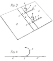
- a binder 1 formed from polypropylene material divided by score lines 2, 3 into a front panel 4, a spine 5, and a rear panel 6.
- the binder includes a pair of binder strips 7, each of which is provided with a head 8 at its free end.
- Each binder strip 7 and its associated head 8 is cut from the polypropylene material.
- each strip 7 and its head 8 are shown fitted into the apertures from which they are cut.
- each of these apertures is designated by reference numeral 9.
- each of the strips 7 extends from the spine 5 at a position 10 located adjacent the score line 3.
- Each of the strips 7 is associated with a rectangular slit or aperture 11 located adjacent the score line 2.
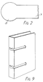
- Each aperture 11 may be formed by punching a rectangular piece of material from the spine 5 or by forming a three sided slit in spine 5. As shown in Figure 2, each head 8 has a partly circular shape, the diameter of the circle being slightly less than the longer dimension of the associated slit 11.
- the binder also includes a strip 12 having a partly circular head 13, strip 12 and head 13 being cut from the rear panel 6 and the strip 12 extending from the rear panel at a position 14 located adjacent an edge 15. A notch 16 is formed in edge 16 adjacent position 14.
- strip 12 may be used for binding a device, such as a pen, to rear panel 6. For reasons of simplicity, strip 12 is not shown in the remaining figures.
- Such material normally consists of sheet artices, such as paper, each of which has a size similar to the front and rear panels 4 and 6 and each of which is provided with a pair of circular holes at a spacing corresponding to the distance between the two strips 7.
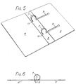
- the strips 7 are removed from their apertures 9.
- the heads 8 and consequently the strips 7 are passed firstly through the holes of the material to be bound.
- the heads 8 are passed from the inner surface of binder 1 through the apertures 11 to the outer surface.
- the shape of the heads 8 and apertures 11 permit this to be performed without deforming either the heads 8 or the apertures 11.
- the heads 8 are pushed though the apertures 9 and thus secured in position by engaging the inner surface of spine 5.
- the binder has a generally neat appearance and the heads 8 are neither present, nor can be seen, on the outside of the binder 1.
- heads 8 may be modified so that the heads can be retained on the outer surface of spine 5 after being passed through apertures 11.
- the shapes of heads 8 and apertures 11 are desirably configured so that the heads can pass through the apertures without causing any deformation to the heads or the apertures.
- the binder is formed from a sheet of polypropylene material.
- the thickness of this material is selected so that the panels 4, 6 and the spine 5 are semi-rigid and so there is sufficient flexibility to bind the strips 7, 12 into a ring shape but insufficient flexibility to allow deformation of the heads after completion of a binding operation.
- Other materials, such as PVC or steel, can be used in place of polypropylene, the thickness being selected so as to provide the properties just mentioned.
Landscapes
- Sheet Holders (AREA)
Claims (7)
- Ringbinder, der einen Materialbogen aufweist, der derart biegbar ist, daß er einen vorderen Einbanddeckel (4) und einen hinteren Einbanddeckel (6) bildet, und wenigstens einen Verbindungsstreifen (7; 12), wobei der oder jeder der Verbindungsstreifen sich vom Bogen von einer jeweiligen ersten Position (10; 14) aus erstreckt, einen jeweiligen Kopf (8; 13), der am freien Ende von dem oder jedem Verbindungsstreifen vorgesehen ist, Mittel (11; 16), um es dem oder jedem der Köpfe zu ermöglichen, von einer Oberfläche des Bogens zu der anderen Oberfläche des Bogens in eine jeweilige zweite Position zu gelangen, und Mittel, um den oder jeden der Köpfe in der Position zu sichern, nachdem er oder sie von der einen Oberfläche zur anderen Oberfläche durchgeführt worden ist, aufweist, dadurch gekennzeichnet, daß die jeweilige erste Position und die jeweilige zweite Position, die mit dem oder jedem der Verbindungsstreifen in Zusammenhang stehen, im Ringbinder derart angeordnet sind, daß sie sich nicht relativ zueinander bewegen, wenn der vordere oder der hintere Einbanddeckel aufeinander zu oder voneinander weg bewegt werden.
- Ringbinder gemäß Anspruch 1, dadurch gekennzeichnet, daß wenigstens ein Verbindungsstreifen (12) angeordnet ist, um einen Gegenstand an einer Oberfläche des Ringbinders zu befestigen.
- Ringbinder gemäß Anspruch 2, dadurch gekennzeichnet, daß für den oder jeden der Verbindungsstreifen (12), der dazu vorgesehen ist, um einen Gegenstand an der Oberfläche des Ringbinders zu befestigen, der Verbindungsstreifen (12) und sein damit zusammenhängender Kopf (13) aus dem Material herausgeschnitten sind, und die jeweilige erste Position zur Kante des Bogens benachbart ist, wodurch das ermöglichende Mittel durch die Kante des Bogens gebildet wird, und das sichernde Mittel durch die Öffnung, die durch Herausschneiden des Streifens und des Kopfes aus dem Material gebildet wird.
- Ringbinder gemäß Anspruch 1, dadurch gekennzeichnet, daß wenigstens zwei der Verbindungsstreifen (7) angeordnet sind, um Blätter im Ringbinder zu binden.
- Ringbinder gemäß Anspruch 4, dadurch gekennzeichnet, daß der Materialbogen so angeordnet ist, daß er gebogen werden kann, um dadurch einen zentralen Einbandrücken (5) zwischen dem vorderen und hinteren Einbanddeckel (4; 6) zu bilden, und daß für jeden Verbindungsstreifen (7), der angeordnet ist, um Blätter in dem Ringbinder zu binden, dessen jeweilige erste und zweite Position am Einbandrücken (5) vorgesehen sind, und daß das ermöglichende Mittel eine Öffnung (11) umfaßt, die im Einbandrücken (5) an der zweiten Position ausgebildet ist.
- Ringbinder gemäß Anspruch 4, dadurch gekennzeichnet, daß für jeden Verbindungsstreifen (7), der vorgesehen ist, um Blätter in dem Ringbinder zu binden, der Kopf (8) und die Öffnung (11) so ausgebildet sind, daß der Kopf (8) durch die Öffnung (11) ohne Verformung gelangen kann.
- Ringbinder gemäß Anspruch 4 oder Anspruch 5, dadurch gekennzeichnet, daß für jeden Verbindungsstreifen (7), der zum Befestigen von Blättern am Ringbinder vorgesehen ist, der Verbindungsstreifen (7) und dessen damit zusammenhängender Kopf (8) aus dem Material herausgeschnitten sind, wodurch das sichernde Mittel durch die Öffnung (9) vorgesehen wird, die durch Herausschneiden des Streifens und Kopfes aus dem Material gebildet ist.
Applications Claiming Priority (3)
| Application Number | Priority Date | Filing Date | Title |
|---|---|---|---|
| GB8820000 | 1988-08-23 | ||
| GB8820000A GB2222113B (en) | 1988-08-23 | 1988-08-23 | Ring binder |
| PCT/GB1989/000961 WO1990002051A1 (en) | 1988-08-23 | 1989-08-18 | Ring binder |
Publications (2)
| Publication Number | Publication Date |
|---|---|
| EP0475939A1 EP0475939A1 (de) | 1992-03-25 |
| EP0475939B1 true EP0475939B1 (de) | 1995-03-22 |
Family
ID=10642570
Family Applications (1)
| Application Number | Title | Priority Date | Filing Date |
|---|---|---|---|
| EP89909792A Expired - Lifetime EP0475939B1 (de) | 1988-08-23 | 1989-08-18 | Ringbinder |
Country Status (6)
| Country | Link |
|---|---|
| US (1) | US5167463A (de) |
| EP (1) | EP0475939B1 (de) |
| AU (1) | AU4186589A (de) |
| DE (1) | DE68921898T2 (de) |
| GB (1) | GB2222113B (de) |
| WO (1) | WO1990002051A1 (de) |
Families Citing this family (21)
| Publication number | Priority date | Publication date | Assignee | Title |
|---|---|---|---|---|
| US5333962A (en) * | 1992-06-05 | 1994-08-02 | Noble T. Johnson | Foldable ring binder-folder |
| SE503832C2 (sv) * | 1995-01-11 | 1996-09-16 | Anders Benson | Tillhållare för mappar avsedda för dokumentförvaring |
| CH691851A5 (de) | 1997-09-17 | 2001-11-15 | Ibico Ag | Binderücken. |
| GB9825606D0 (en) * | 1998-11-24 | 1999-01-13 | Duraweld Ltd | Compact disc storage |
| EP1177107A1 (de) | 1999-04-09 | 2002-02-06 | ACCO Brands, Inc. | Befestigungsmittel für einen ordner |
| US6099187A (en) * | 1999-06-05 | 2000-08-08 | Univenture, Inc. | Storage device |
| UA72525C2 (uk) | 1999-06-05 | 2005-03-15 | Юнівенчер, Інк. | Пристрій для зберігання (варіанти) |
| US20040240967A1 (en) * | 2001-08-29 | 2004-12-02 | Phillip Crudo | Binding elements for binding a wide range of thicknesses of stacks of sheets |
| US20040240930A1 (en) * | 2003-01-08 | 2004-12-02 | Smith Braden Lindley | Binding device for holding sheet materials or sleeves for compact discs |
| US7018125B2 (en) * | 2003-05-14 | 2006-03-28 | Ken Jui Su | Notebook having integral binder members |
| CA2573096A1 (en) | 2004-07-12 | 2006-02-16 | General Binding Corporation | Binding element and plurality of binding elements particularly suited for automated processes |
| US9290035B2 (en) | 2005-02-18 | 2016-03-22 | ACCO Brands Corporation | Refillable notebook with release mechanism |
| CA2734076C (en) * | 2005-02-18 | 2013-05-07 | Meadwestvaco Corporation | Refillable notebook |
| US8123448B2 (en) | 2005-08-16 | 2012-02-28 | General Binding Corporation | Apparatus and methods for automatically binding a stack of sheets with a nonspiral binding element |
| USD620977S1 (en) | 2006-08-04 | 2010-08-03 | General Binding Corporation | Binding element |
| GB2474682B (en) * | 2009-10-23 | 2013-08-07 | Thomas Simon Corbishley | Ring binder |
| US10446060B2 (en) * | 2013-03-15 | 2019-10-15 | Abbott Cardiovascular Systems, Inc. | Methods, systems and kit for demonstrating medical procedure |
| CA2990038A1 (en) | 2015-06-30 | 2017-01-05 | ACCO Brands Corporation | Flexible binding mechanism |
| UA109219U (uk) * | 2016-06-07 | 2016-08-10 | Олег Сергійович Ігнатьєв | Пристрій для рознімного скріплення листів з перфорацією |
| US10245409B2 (en) * | 2016-07-08 | 2019-04-02 | Fresenius Medical Care Holdings, Inc. | Packaging and organizing coils of medical tubing |
| PL422227A1 (pl) * | 2017-07-14 | 2019-01-28 | Bartłomiej Nazar | Sposób mocowania i przechowywania zwojów materiału na arkuszu elastycznego, dającego się odkształcać materiału. |
Citations (1)
| Publication number | Priority date | Publication date | Assignee | Title |
|---|---|---|---|---|
| FR2164841A3 (de) * | 1971-12-21 | 1973-08-03 | Zucher Ziegeleien |
Family Cites Families (9)
| Publication number | Priority date | Publication date | Assignee | Title |
|---|---|---|---|---|
| GB1209770A (en) * | 1967-10-30 | 1970-10-21 | Carl Gustaf Moller | Loose leaf binder |
| US4174909A (en) * | 1973-07-19 | 1979-11-20 | Gerhard Jahn | Loose leaf binder |
| US4192620A (en) * | 1975-12-01 | 1980-03-11 | Gerhard Jahn | Loose leaf binder |
| US4261664A (en) * | 1978-07-17 | 1981-04-14 | Crawford Industries, Inc. | One-piece report binder |
| US4256411A (en) * | 1978-12-15 | 1981-03-17 | National Blank Book Company, Inc. | File folder with integral loose leaf binder rings |
| DE3708432A1 (de) * | 1987-03-16 | 1988-09-29 | Mauser Werke Gmbh | Spundfass |
| DE8708482U1 (de) * | 1987-03-27 | 1987-10-08 | Helfrecht, Manfred, 8598 Waldershof | Schreibstifthalter |
| FR2614841B1 (fr) * | 1987-05-04 | 1993-06-04 | Jowa Sa | Reliure a anneaux ouvrables pour documents et autres objets presentes en feuilles perforees |
| GB2213432B (en) * | 1987-12-09 | 1991-11-27 | Thomas Simon Corbishley | Ring binder |
-
1988
- 1988-08-23 GB GB8820000A patent/GB2222113B/en not_active Expired - Lifetime
-
1989
- 1989-08-18 AU AU41865/89A patent/AU4186589A/en not_active Abandoned
- 1989-08-18 WO PCT/GB1989/000961 patent/WO1990002051A1/en not_active Ceased
- 1989-08-18 DE DE68921898T patent/DE68921898T2/de not_active Expired - Fee Related
- 1989-08-18 EP EP89909792A patent/EP0475939B1/de not_active Expired - Lifetime
- 1989-08-18 US US07/651,232 patent/US5167463A/en not_active Expired - Fee Related
Patent Citations (1)
| Publication number | Priority date | Publication date | Assignee | Title |
|---|---|---|---|---|
| FR2164841A3 (de) * | 1971-12-21 | 1973-08-03 | Zucher Ziegeleien |
Also Published As
| Publication number | Publication date |
|---|---|
| DE68921898T2 (de) | 1995-07-20 |
| GB8820000D0 (en) | 1988-09-21 |
| GB2222113B (en) | 1992-04-08 |
| WO1990002051A1 (en) | 1990-03-08 |
| AU4186589A (en) | 1990-03-23 |
| US5167463A (en) | 1992-12-01 |
| EP0475939A1 (de) | 1992-03-25 |
| GB2222113A (en) | 1990-02-28 |
| DE68921898D1 (de) | 1995-04-27 |
Similar Documents
| Publication | Publication Date | Title |
|---|---|---|
| EP0475939B1 (de) | Ringbinder | |
| US4419837A (en) | Apparatus for displaying advertising material | |
| US4261664A (en) | One-piece report binder | |
| DE2640890A1 (de) | Behaelter fuer eine videoplatte | |
| US5997207A (en) | Sheet assembly with an optional pocket | |
| DE69416327T2 (de) | Holterung- und anzeigevorrichtung für kartenähnliche artikel | |
| EP1129866B1 (de) | Etikett und Verfahren zum Anbringen | |
| US2407656A (en) | Binding element | |
| GB2100649A (en) | A perforating jig for use when perforating sheet material. | |
| US2264119A (en) | Indexed book | |
| US4620724A (en) | Binding strips for rectangular hole punched paper | |
| US4950097A (en) | File folder and method of manufacture | |
| US4669191A (en) | Paper perforating device | |
| GB2219573A (en) | A holder for a compact disc | |
| GB2213432A (en) | A ring binder | |
| US2123625A (en) | Binding device | |
| US20020041789A1 (en) | Binders with inside and outside pockets and methods for constructing same | |
| USD416041S (en) | Jig for perforating paper sheets and binding said paper sheets perforated on a ring binder | |
| US2317047A (en) | Sheet fastening means | |
| US4819534A (en) | Removable knives for punching cardboard slots | |
| US6309130B1 (en) | Organizer strip system, tool and method of use | |
| US3645637A (en) | Bookbinder | |
| US4560299A (en) | Presentation folder | |
| USD408453S (en) | Punch used for jig for perforating paper sheets and for binding said paper sheets perforated on a ring binder | |
| EP0802070B1 (de) | Zuschnitt für eine Decke |
Legal Events
| Date | Code | Title | Description |
|---|---|---|---|
| PUAI | Public reference made under article 153(3) epc to a published international application that has entered the european phase |
Free format text: ORIGINAL CODE: 0009012 |
|
| 17P | Request for examination filed |
Effective date: 19910205 |
|
| AK | Designated contracting states |
Kind code of ref document: A1 Designated state(s): DE FR IT NL |
|
| 17Q | First examination report despatched |
Effective date: 19930812 |
|
| GRAA | (expected) grant |
Free format text: ORIGINAL CODE: 0009210 |
|
| AK | Designated contracting states |
Kind code of ref document: B1 Designated state(s): DE FR IT NL |
|
| REF | Corresponds to: |
Ref document number: 68921898 Country of ref document: DE Date of ref document: 19950427 |
|
| ITF | It: translation for a ep patent filed | ||
| ET | Fr: translation filed | ||
| PLBE | No opposition filed within time limit |
Free format text: ORIGINAL CODE: 0009261 |
|
| STAA | Information on the status of an ep patent application or granted ep patent |
Free format text: STATUS: NO OPPOSITION FILED WITHIN TIME LIMIT |
|
| 26N | No opposition filed | ||
| PGFP | Annual fee paid to national office [announced via postgrant information from national office to epo] |
Ref country code: FR Payment date: 20000803 Year of fee payment: 12 |
|
| PGFP | Annual fee paid to national office [announced via postgrant information from national office to epo] |
Ref country code: NL Payment date: 20000829 Year of fee payment: 12 |
|
| PGFP | Annual fee paid to national office [announced via postgrant information from national office to epo] |
Ref country code: DE Payment date: 20001025 Year of fee payment: 12 |
|
| PG25 | Lapsed in a contracting state [announced via postgrant information from national office to epo] |
Ref country code: NL Free format text: LAPSE BECAUSE OF NON-PAYMENT OF DUE FEES Effective date: 20020301 |
|
| PG25 | Lapsed in a contracting state [announced via postgrant information from national office to epo] |
Ref country code: FR Free format text: LAPSE BECAUSE OF NON-PAYMENT OF DUE FEES Effective date: 20020430 |
|
| NLV4 | Nl: lapsed or anulled due to non-payment of the annual fee |
Effective date: 20020301 |
|
| PG25 | Lapsed in a contracting state [announced via postgrant information from national office to epo] |
Ref country code: DE Free format text: LAPSE BECAUSE OF NON-PAYMENT OF DUE FEES Effective date: 20020501 |
|
| REG | Reference to a national code |
Ref country code: FR Ref legal event code: ST |
|
| PG25 | Lapsed in a contracting state [announced via postgrant information from national office to epo] |
Ref country code: IT Free format text: LAPSE BECAUSE OF NON-PAYMENT OF DUE FEES;WARNING: LAPSES OF ITALIAN PATENTS WITH EFFECTIVE DATE BEFORE 2007 MAY HAVE OCCURRED AT ANY TIME BEFORE 2007. THE CORRECT EFFECTIVE DATE MAY BE DIFFERENT FROM THE ONE RECORDED. Effective date: 20050818 |