EP0476823B1 - Melting disposal apparatus for injection needles - Google Patents
Melting disposal apparatus for injection needles Download PDFInfo
- Publication number
- EP0476823B1 EP0476823B1 EP91307269A EP91307269A EP0476823B1 EP 0476823 B1 EP0476823 B1 EP 0476823B1 EP 91307269 A EP91307269 A EP 91307269A EP 91307269 A EP91307269 A EP 91307269A EP 0476823 B1 EP0476823 B1 EP 0476823B1
- Authority
- EP
- European Patent Office
- Prior art keywords
- injection needle
- plasma discharge
- injection
- needle
- zone
- Prior art date
- Legal status (The legal status is an assumption and is not a legal conclusion. Google has not performed a legal analysis and makes no representation as to the accuracy of the status listed.)
- Expired - Lifetime
Links
- 238000002347 injection Methods 0.000 title claims abstract description 58
- 239000007924 injection Substances 0.000 title claims abstract description 58
- 238000002844 melting Methods 0.000 title claims abstract description 22
- 230000008018 melting Effects 0.000 title claims abstract description 22
- WFKWXMTUELFFGS-UHFFFAOYSA-N tungsten Chemical compound [W] WFKWXMTUELFFGS-UHFFFAOYSA-N 0.000 claims description 8
- 238000000034 method Methods 0.000 claims description 6
- 229910052721 tungsten Inorganic materials 0.000 claims description 6
- 239000010937 tungsten Substances 0.000 claims description 6
- 210000000078 claw Anatomy 0.000 description 14
- 238000010276 construction Methods 0.000 description 3
- 239000007769 metal material Substances 0.000 description 2
- 229910001220 stainless steel Inorganic materials 0.000 description 2
- 239000010935 stainless steel Substances 0.000 description 2
- 208000035143 Bacterial infection Diseases 0.000 description 1
- 208000022362 bacterial infectious disease Diseases 0.000 description 1
- 230000015572 biosynthetic process Effects 0.000 description 1
- 229910010293 ceramic material Inorganic materials 0.000 description 1
- 238000007796 conventional method Methods 0.000 description 1
- 239000000428 dust Substances 0.000 description 1
- 239000011521 glass Substances 0.000 description 1
- 229910052573 porcelain Inorganic materials 0.000 description 1
- 239000002699 waste material Substances 0.000 description 1
Images





Classifications
-
- A—HUMAN NECESSITIES
- A61—MEDICAL OR VETERINARY SCIENCE; HYGIENE
- A61M—DEVICES FOR INTRODUCING MEDIA INTO, OR ONTO, THE BODY; DEVICES FOR TRANSDUCING BODY MEDIA OR FOR TAKING MEDIA FROM THE BODY; DEVICES FOR PRODUCING OR ENDING SLEEP OR STUPOR
- A61M5/00—Devices for bringing media into the body in a subcutaneous, intra-vascular or intramuscular way; Accessories therefor, e.g. filling or cleaning devices, arm-rests
- A61M5/178—Syringes
-
- A—HUMAN NECESSITIES
- A61—MEDICAL OR VETERINARY SCIENCE; HYGIENE
- A61M—DEVICES FOR INTRODUCING MEDIA INTO, OR ONTO, THE BODY; DEVICES FOR TRANSDUCING BODY MEDIA OR FOR TAKING MEDIA FROM THE BODY; DEVICES FOR PRODUCING OR ENDING SLEEP OR STUPOR
- A61M5/00—Devices for bringing media into the body in a subcutaneous, intra-vascular or intramuscular way; Accessories therefor, e.g. filling or cleaning devices, arm-rests
- A61M5/178—Syringes
- A61M5/31—Details
- A61M5/32—Needles; Details of needles pertaining to their connection with syringe or hub; Accessories for bringing the needle into, or holding the needle on, the body; Devices for protection of needles
- A61M5/3205—Apparatus for removing or disposing of used needles or syringes, e.g. containers; Means for protection against accidental injuries from used needles
- A61M5/3278—Apparatus for destroying used needles or syringes
-
- A—HUMAN NECESSITIES
- A61—MEDICAL OR VETERINARY SCIENCE; HYGIENE
- A61M—DEVICES FOR INTRODUCING MEDIA INTO, OR ONTO, THE BODY; DEVICES FOR TRANSDUCING BODY MEDIA OR FOR TAKING MEDIA FROM THE BODY; DEVICES FOR PRODUCING OR ENDING SLEEP OR STUPOR
- A61M5/00—Devices for bringing media into the body in a subcutaneous, intra-vascular or intramuscular way; Accessories therefor, e.g. filling or cleaning devices, arm-rests
- A61M5/178—Syringes
- A61M5/31—Details
- A61M5/32—Needles; Details of needles pertaining to their connection with syringe or hub; Accessories for bringing the needle into, or holding the needle on, the body; Devices for protection of needles
- A61M5/3205—Apparatus for removing or disposing of used needles or syringes, e.g. containers; Means for protection against accidental injuries from used needles
- A61M5/3278—Apparatus for destroying used needles or syringes
- A61M2005/3283—Apparatus for destroying used needles or syringes using electric current between electrodes
-
- Y—GENERAL TAGGING OF NEW TECHNOLOGICAL DEVELOPMENTS; GENERAL TAGGING OF CROSS-SECTIONAL TECHNOLOGIES SPANNING OVER SEVERAL SECTIONS OF THE IPC; TECHNICAL SUBJECTS COVERED BY FORMER USPC CROSS-REFERENCE ART COLLECTIONS [XRACs] AND DIGESTS
- Y10—TECHNICAL SUBJECTS COVERED BY FORMER USPC
- Y10S—TECHNICAL SUBJECTS COVERED BY FORMER USPC CROSS-REFERENCE ART COLLECTIONS [XRACs] AND DIGESTS
- Y10S422/00—Chemical apparatus and process disinfecting, deodorizing, preserving, or sterilizing
- Y10S422/906—Plasma or ion generation means
Definitions
- the present invention relates to an apparatus in which injection needles are melted through high temperature thereby safely and easily disposing of them.
- the injection needle used in hospital or the like has been disposed of in a specific way so that the injection needles are collected in a predetermined vessel with sufficient carefulness so as not to puncture fingers of person or the like. Therefore, it is necessary to treat the used injection needle very carefully so as not to produce bacterial infection.
- the object of the present invention is to alleviate the problems of the conventional technique.
- EP-A-0,136,392 discloses a syringe needle destroyer in which an inserted needle short-circuits a pair of electrodes causing a flash of current to flow which heats the needle sufficiently to melt it.
- an apparatus for disposal of injection needles by melting said apparatus being characterised by comprising: means for generating electromagnetic microwaves; means for generating, by irradiation with said electromagnetic microwaves, a plasma discharge having a high temperature for melting a needle, and moving means for automatically inserting an injection needle into a zone in which said plasma discharge is produced, and automatically releasing the remains of said injection needle from said zone after said injection needle has been melted.
- method of disposing of injection needles comprising: generating electromagnetic microwaves; generating, by irradiation with the electromagnetic microwaves, a plasma discharge having a high temperature for melting a needle; automatically inserting the injection needle into a zone in which the plasma discharge is produced; and melting an injection needle by holding it in the plasma discharge; and automatically releasing the remains of the injection needle from the zone after the injection needle has been melted.
- Fig. 1 shows an injection needle melting disposal apparatus.
- Figs. 2 and 3 show a schematic construction of the apparatus in which a microwave generator 2 (100 volt, 500 wattage) for generaring an electromagnetic microwave (about 2450 KHz) is disposed on the side wall of a melting furnace 3 through a waveguide tube 4. There is provided moving means M for automatically inserting an injection needle 5 into the melting furnace 3 and automatically returning it after melting thereof.
- a microwave generator 2 100 volt, 500 wattage
- an electromagnetic microwave about 2450 KHz
- tungsten wires W1 and W2 fixed on a supporting plate, the end points of each of the two wires being disposed adjacent to each other (with a gap between end points of about 2 mm).
- An opening 7 in Fig. 4 is provided on the side surface of the melting furnace made of stainless steel for the waveguide tube 4, and the electromagnetic microwares are irradiated from the opening 7 into the tungsten wires W1 and W2 (having diameter about 1.6 mm) mounted within the melting furnace 3.
- a plasma discharge 8 is produced at the zone between the end points of the tungsten wires W1 and W2 respectively as shown in Fig. 5, and a high temperature of about 4000°C - 5000°C is produced.
- the injection needle 5 is disposed in the plasma discharge 8.
- the time required for disposing one injection needle 5 is about 5-10 seconds.
- the electromagnetic microwaves are generated only the time corresponding the above-mentioned disposal time.
- the end point of the tungsten wire is gradually worn thereby increasing the distance between the end points, and therefore the tungsten wire is adjustably mounted on a supporting plate 6 so as to be pulled slightly.
- moving means has a pair of claws M1 and M2 for holding the sleeve 5A of the injection needle, and the claws M1 and M2 is rotatably mounted on a supporting member M3 and the claws M1 and M2 are fixed with a pair of gears M4 and M5 coupled with each other.
- a spring 9 between the claw M2 and the supporting member M3. Therefore, by inserting the injection needle 5 of an injection syringe 5B into the space between the upper portions of the claws M1 and M2, the sleeve 5A of the injection needle 5 slides the slanted surface portions M11 (Fig.
- the supporting member M3 for supporting the claws M1 and M2 is adapted to be slidable on a pair of rails R1 and R2 for guiding the supporting member M3.
- the supporting member M3 has an arm M6 one end of which is rotatably mounted on the supporting member M3.
- the other end of the arm M6 has an elongated hole M7 into which a pin M9 mounted at the periphery portion of a disk M8 is inserted.
- a spring 10 between the pin M9 and a pin M10 mounted on the arm M6.
- the disk M8 is rotated in the direction of arrow B by using a motor 11 thereby moving the supporting member M3 mounting the claws M1 and M2 holding the injection needle 5, along the rails R1 and R2 in the bi-direction of arrow C.
- the moving injection needle 5 can be inserted into a small hole 12 mounted on the front surface of the melting furnace 3 until almost the entire injection needle 5 has been inserted.
- the injection needle 5 is melted in about 5-10 seconds, and the original form of the injection needle 5 is no longer maintained, thereby forming a small ball (waste).
- the wasted needle is pulled from the small hole 12 backwardly passing through a restore position as shown in Fig. 2.
- a slanted portion 13A provided at the end point of a release member 13 is inserted into the space between the claws M1 and M2 against the resilient force of the spring 9 thereby releasing the injection needle 5 from the claws M1 and M2.
- the molten injection needle drops into a collection box 14.
- the claws M1 and M2 are restored to the restore position as shown in Fig. 2.
- the main switch SW1 of the disposal apparatus is actuated, and the injection needle 5 is held by the claws M1 and M2, and then a start switch SW2 is actuated. Then, the injection needle 5 is automatically molten in the melting furnace 3 for a short time, and then the injection needle 5 maintained by the claws M1 and M2 is pulled out from the melting furnace 3 and released by the releasing member thereby automatically dropping to the collecting box 14, under the control by a control device (not shown).
- the present invention utilizing a plasma discharge with high temperature can be applied also to cut a metallic material, weld a metallic material such as plate or rod, and melt or weld ceramic materials such as porcelain or glass.
- a sharp end point of the injection needle is molten to deform to a ball-like formation with safety, and further it is completely sterilized due to the high temperature, as a result it can be dealt with just like a normal dust.
Landscapes
- Health & Medical Sciences (AREA)
- Engineering & Computer Science (AREA)
- General Health & Medical Sciences (AREA)
- Public Health (AREA)
- Anesthesiology (AREA)
- Biomedical Technology (AREA)
- Heart & Thoracic Surgery (AREA)
- Hematology (AREA)
- Life Sciences & Earth Sciences (AREA)
- Animal Behavior & Ethology (AREA)
- Veterinary Medicine (AREA)
- Vascular Medicine (AREA)
- Environmental & Geological Engineering (AREA)
- Processing Of Solid Wastes (AREA)
- Accommodation For Nursing Or Treatment Tables (AREA)
- Gasification And Melting Of Waste (AREA)
- Processing And Handling Of Plastics And Other Materials For Molding In General (AREA)
- Apparatus For Disinfection Or Sterilisation (AREA)
- Constitution Of High-Frequency Heating (AREA)
- Infusion, Injection, And Reservoir Apparatuses (AREA)
Abstract
Description
- The present invention relates to an apparatus in which injection needles are melted through high temperature thereby safely and easily disposing of them.
- Hitherto, the injection needle used in hospital or the like has been disposed of in a specific way so that the injection needles are collected in a predetermined vessel with sufficient carefulness so as not to puncture fingers of person or the like. Therefore, it is necessary to treat the used injection needle very carefully so as not to produce bacterial infection.
- The object of the present invention is to alleviate the problems of the conventional technique.
- EP-A-0,136,392 discloses a syringe needle destroyer in which an inserted needle short-circuits a pair of electrodes causing a flash of current to flow which heats the needle sufficiently to melt it.
- According to one aspect of the present invention, there is provided an apparatus for disposal of injection needles by melting, said apparatus being characterised by comprising: means for generating electromagnetic microwaves; means for generating, by irradiation with said electromagnetic microwaves, a plasma discharge having a high temperature for melting a needle, and moving means for automatically inserting an injection needle into a zone in which said plasma discharge is produced, and automatically releasing the remains of said injection needle from said zone after said injection needle has been melted.
- According to another aspect of the present invention there is provided method of disposing of injection needles, the method being characterised by comprising: generating electromagnetic microwaves; generating, by irradiation with the electromagnetic microwaves, a plasma discharge having a high temperature for melting a needle; automatically inserting the injection needle into a zone in which the plasma discharge is produced; and melting an injection needle by holding it in the plasma discharge; and automatically releasing the remains of the injection needle from the zone after the injection needle has been melted.
- In order that the present invention may be better understood, the following description is given, merely by way of example, with reference to the drawings, in which:-
- Fig. 1 is a perspective view showing the injection needle melting apparatus as one embodiment of the present invention,
- Figs. 2 and 3 are schematic side sectional and perspective views respectively showing the interior constructions,
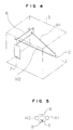
- Fig. 4 is a schematic and perspective view showing the interior of the melting furnace,
- Fig. 5 is a front view showing the end points of tungsten wires, and
- Figs. 6 and 7 are schematic and perspective views respectively showing the construction of moving means for automatically moving the injection needle.
- One embodiment of the present invention will be explained with reference to the attached drawings hereinafter.
- Fig. 1 shows an injection needle melting disposal apparatus. Figs. 2 and 3 show a schematic construction of the apparatus in which a microwave generator 2 (100 volt, 500 wattage) for generaring an electromagnetic microwave (about 2450 KHz) is disposed on the side wall of a
melting furnace 3 through a waveguide tube 4. There is provided moving means M for automatically inserting aninjection needle 5 into themelting furnace 3 and automatically returning it after melting thereof. - In the interior of a
melting furnace 3 made of stainless steel or the like, there are provided two tungsten wires W1 and W2 fixed on a supporting plate, the end points of each of the two wires being disposed adjacent to each other (with a gap between end points of about 2 mm). - An
opening 7 in Fig. 4 is provided on the side surface of the melting furnace made of stainless steel for the waveguide tube 4, and the electromagnetic microwares are irradiated from theopening 7 into the tungsten wires W1 and W2 (having diameter about 1.6 mm) mounted within themelting furnace 3. - Upon the irradiation of the electromagnetic microwave, a plasma discharge 8 is produced at the zone between the end points of the tungsten wires W1 and W2 respectively as shown in Fig. 5, and a high temperature of about 4000°C - 5000°C is produced. The
injection needle 5 is disposed in the plasma discharge 8. The time required for disposing oneinjection needle 5 is about 5-10 seconds. The electromagnetic microwaves are generated only the time corresponding the above-mentioned disposal time. The end point of the tungsten wire is gradually worn thereby increasing the distance between the end points, and therefore the tungsten wire is adjustably mounted on a supportingplate 6 so as to be pulled slightly. - As shown in Figs. 6 and 7, moving means has a pair of claws M1 and M2 for holding the
sleeve 5A of the injection needle, and the claws M1 and M2 is rotatably mounted on a supporting member M3 and the claws M1 and M2 are fixed with a pair of gears M4 and M5 coupled with each other. There is provided a spring 9 between the claw M2 and the supporting member M3. Therefore, by inserting theinjection needle 5 of aninjection syringe 5B into the space between the upper portions of the claws M1 and M2, thesleeve 5A of theinjection needle 5 slides the slanted surface portions M11 (Fig. 7) of the claws M1 and M2 and then theinjection needle 5 is pinched by the claws M1 and M2 having the resilient force of the spring 9. Upon pulling theinjection syringe 5B, thesleeve 5A of theinjection needle 5 is stopped by a pair of projected plates H1 and H2 (Fig. 7) and therefore theinjection needle 5 can be easily removed from theinjection syringe 5B. The supporting member M3 for supporting the claws M1 and M2 is adapted to be slidable on a pair of rails R1 and R2 for guiding the supporting member M3. The supporting member M3 has an arm M6 one end of which is rotatably mounted on the supporting member M3. The other end of the arm M6 has an elongated hole M7 into which a pin M9 mounted at the periphery portion of a disk M8 is inserted. There is provided aspring 10 between the pin M9 and a pin M10 mounted on the arm M6. The disk M8 is rotated in the direction of arrow B by using amotor 11 thereby moving the supporting member M3 mounting the claws M1 and M2 holding theinjection needle 5, along the rails R1 and R2 in the bi-direction of arrow C. Themoving injection needle 5 can be inserted into asmall hole 12 mounted on the front surface of themelting furnace 3 until almost theentire injection needle 5 has been inserted. Theinjection needle 5 is melted in about 5-10 seconds, and the original form of the
injection needle 5 is no longer maintained, thereby forming a small ball (waste). The wasted needle is pulled from thesmall hole 12 backwardly passing through a restore position as shown in Fig. 2. Aslanted portion 13A provided at the end point of arelease member 13 is inserted into the space between the claws M1 and M2 against the resilient force of the spring 9 thereby releasing theinjection needle 5 from the claws M1 and M2. As a result, the molten injection needle drops into acollection box 14. Then, the claws M1 and M2 are restored to the restore position as shown in Fig. 2. - According to the disposal apparatus mentioned above, the main switch SW1 of the disposal apparatus is actuated, and the
injection needle 5 is held by the claws M1 and M2, and then a start switch SW2 is actuated. Then, theinjection needle 5 is automatically molten in themelting furnace 3 for a short time, and then theinjection needle 5 maintained by the claws M1 and M2 is pulled out from themelting furnace 3 and released by the releasing member thereby automatically dropping to thecollecting box 14, under the control by a control device (not shown). - The present invention utilizing a plasma discharge with high temperature can be applied also to cut a metallic material, weld a metallic material such as plate or rod, and melt or weld ceramic materials such as porcelain or glass.
- As mentioned above, according to the present invention a sharp end point of the injection needle is molten to deform to a ball-like formation with safety, and further it is completely sterilized due to the high temperature, as a result it can be dealt with just like a normal dust.
Claims (6)
- An apparatus for disposal of injection needles (5) by melting, said apparatus being characterised by comprising: means (2) for generating electromagnetic microwaves; means (W1,W2) for generating, by irradiation with said electromagnetic microwaves, a plasma discharge (8) having a high temperature for melting a needle, and moving means (M1-M10) for automatically inserting an injection needle (5) into a zone (8) in which said plasma discharge is produced, and automatically releasing the remains of said injection needle (5) from said zone (8) after said injection needle (5) has been melted.
- An apparatus for disposal of injection needles according to claim 1, wherein said means (W1,W2) for generating a plasma discharge comprises two tungsten wires (W1,W2) disposed with their ends adjacent to each other, said zone (8) in which said plasma discharge is produced by said irradiation being between said ends.
- An apparatus for disposal of injection needles according to claim 1 or 2, wherein in use said injection needles (5) are heated and melted by said plasma discharge (8) having a high temperature within the range of about 4000°C to about 5000°C.
- A method of disposing of injection needles (5), said method being characterised by comprising: generating electromagnetic microwaves; generating, by irradiation with said electromagnetic microwaves, a plasma discharge (8) having a high temperature for melting a needle; automatically inserting said injection needle (5) into a zone (8) in which said plasma discharge is produced; and melting an injection needle by holding it in said plasma discharge; and automatically releasing the remains of said injection needle (5) from said zone (8) after said injection needle (5) has been melted.
- A method of disposing of injection needles according to claim 4, wherein said plasma discharge is generated by two tungsten wires (W1,W2) disposed with their ends adjacent to each other, said zone (8) in which said plasma discharge is produced by said irradiation being between said ends.
- A method of disposing of injection needles according to claim 4 or 5, wherein the high temperature of said plasma discharge is within the range of about 4000°C to about 5000°C.
Applications Claiming Priority (2)
| Application Number | Priority Date | Filing Date | Title |
|---|---|---|---|
| JP248376/90 | 1990-09-18 | ||
| JP2248376A JP2958086B2 (en) | 1990-09-18 | 1990-09-18 | Melting device for injection needle |
Publications (2)
| Publication Number | Publication Date |
|---|---|
| EP0476823A1 EP0476823A1 (en) | 1992-03-25 |
| EP0476823B1 true EP0476823B1 (en) | 1995-02-15 |
Family
ID=17177184
Family Applications (1)
| Application Number | Title | Priority Date | Filing Date |
|---|---|---|---|
| EP91307269A Expired - Lifetime EP0476823B1 (en) | 1990-09-18 | 1991-08-08 | Melting disposal apparatus for injection needles |
Country Status (9)
| Country | Link |
|---|---|
| US (1) | US5276297A (en) |
| EP (1) | EP0476823B1 (en) |
| JP (1) | JP2958086B2 (en) |
| KR (1) | KR0145115B1 (en) |
| AT (1) | ATE118361T1 (en) |
| CA (1) | CA2048827C (en) |
| DE (1) | DE69107385T2 (en) |
| DK (1) | DK0476823T3 (en) |
| ES (1) | ES2071226T3 (en) |
Cited By (2)
| Publication number | Priority date | Publication date | Assignee | Title |
|---|---|---|---|---|
| EP1614440A1 (en) | 2004-07-08 | 2006-01-11 | Banner Ventures LLC | Method of destroying surgical instruments by melting and apparatus for carrying out the method |
| US9579469B2 (en) | 2011-06-08 | 2017-02-28 | Becton, Dickinson And Company | Medical needle removal and storage device |
Families Citing this family (35)
| Publication number | Priority date | Publication date | Assignee | Title |
|---|---|---|---|---|
| US5268549A (en) * | 1990-06-01 | 1993-12-07 | Butler William F | Method and apparatus for destroying a syringe needle |
| US5611947A (en) * | 1994-09-07 | 1997-03-18 | Alliant Techsystems, Inc. | Induction steam plasma torch for generating a steam plasma for treating a feed slurry |
| US6169259B1 (en) * | 1995-05-31 | 2001-01-02 | Robert M. Hall | Portable device for electrically destroying needles |
| US5762009A (en) * | 1995-06-07 | 1998-06-09 | Alliant Techsystems, Inc. | Plasma energy recycle and conversion (PERC) reactor and process |
| US5852267A (en) * | 1995-11-30 | 1998-12-22 | Taiyo Elecs Co., Ltd. | Injection needle safety disposal apparatus |
| CA2167332C (en) | 1996-01-16 | 1998-04-21 | Robert M. Walker | Method and electrical apparatus for destroying medical instruments |
| US5771818A (en) * | 1996-05-20 | 1998-06-30 | Prometron Technics Co., Ltd. | Cooling system for waste disposal device |
| US5710404A (en) * | 1996-07-26 | 1998-01-20 | Biotronix 2000, Inc. | Portable hand-held device for incinerating needles |
| US6384362B1 (en) | 2000-02-09 | 2002-05-07 | Joey B. Adkins | Method and apparatus for destroying needles |
| US6621031B2 (en) * | 2001-04-06 | 2003-09-16 | Carlile R. Stevens | Syringe and needle destruction device |
| EP1361437A1 (en) * | 2002-05-07 | 2003-11-12 | Centre National De La Recherche Scientifique (Cnrs) | A novel biological cancer marker and methods for determining the cancerous or non-cancerous phenotype of cells |
| US7497922B2 (en) * | 2002-05-08 | 2009-03-03 | Btu International, Inc. | Plasma-assisted gas production |
| US20060233682A1 (en) * | 2002-05-08 | 2006-10-19 | Cherian Kuruvilla A | Plasma-assisted engine exhaust treatment |
| JP2005524963A (en) * | 2002-05-08 | 2005-08-18 | ダナ・コーポレーション | Plasma catalyst |
| US20060062930A1 (en) * | 2002-05-08 | 2006-03-23 | Devendra Kumar | Plasma-assisted carburizing |
| US7432470B2 (en) | 2002-05-08 | 2008-10-07 | Btu International, Inc. | Surface cleaning and sterilization |
| US7465362B2 (en) * | 2002-05-08 | 2008-12-16 | Btu International, Inc. | Plasma-assisted nitrogen surface-treatment |
| US7638727B2 (en) * | 2002-05-08 | 2009-12-29 | Btu International Inc. | Plasma-assisted heat treatment |
| US20060057016A1 (en) * | 2002-05-08 | 2006-03-16 | Devendra Kumar | Plasma-assisted sintering |
| US20060237398A1 (en) * | 2002-05-08 | 2006-10-26 | Dougherty Mike L Sr | Plasma-assisted processing in a manufacturing line |
| US20050233091A1 (en) * | 2002-05-08 | 2005-10-20 | Devendra Kumar | Plasma-assisted coating |
| US7560657B2 (en) * | 2002-05-08 | 2009-07-14 | Btu International Inc. | Plasma-assisted processing in a manufacturing line |
| US20060228497A1 (en) * | 2002-05-08 | 2006-10-12 | Satyendra Kumar | Plasma-assisted coating |
| US7504061B2 (en) * | 2002-05-08 | 2009-03-17 | Leonhard Kurz Gmbh & Co., Kg | Method of decorating large plastic 3D objects |
| US7498066B2 (en) * | 2002-05-08 | 2009-03-03 | Btu International Inc. | Plasma-assisted enhanced coating |
| US7445817B2 (en) * | 2002-05-08 | 2008-11-04 | Btu International Inc. | Plasma-assisted formation of carbon structures |
| US7494904B2 (en) * | 2002-05-08 | 2009-02-24 | Btu International, Inc. | Plasma-assisted doping |
| CN100460128C (en) * | 2002-12-04 | 2009-02-11 | Btu国际公司 | Plasma-assisted melting |
| US7189940B2 (en) * | 2002-12-04 | 2007-03-13 | Btu International Inc. | Plasma-assisted melting |
| EP1579023A4 (en) * | 2002-12-04 | 2009-07-22 | Btu Int | Plasma-assisted melting |
| WO2006127037A2 (en) * | 2004-11-05 | 2006-11-30 | Dana Corporation | Atmospheric pressure processing using microwave-generated plasmas |
| EP3659658A1 (en) * | 2011-06-08 | 2020-06-03 | Becton, Dickinson and Company | Medical needle removal and storage device |
| CN108273834B (en) * | 2018-04-03 | 2019-05-07 | 济南市儿童医院 | Medical infusing device recovery method |
| CN112705553B (en) * | 2020-12-15 | 2022-06-21 | 青岛市黄岛区中心医院 | Environment-friendly medical disposable article processing device |
| CN112755337A (en) * | 2021-01-18 | 2021-05-07 | 浙江大学 | Semi-automatic insulin needle processing apparatus |
Family Cites Families (6)
| Publication number | Priority date | Publication date | Assignee | Title |
|---|---|---|---|---|
| US4423303A (en) * | 1980-05-06 | 1983-12-27 | Tokyo Shibaura Denki Kabushiki Kaisha | Apparatus for treating powdery materials utilizing microwave plasma |
| JPS6040060A (en) * | 1983-08-08 | 1985-03-02 | シユイ チン−ロン | Miniaturized syringe disposal vessel |
| US4931261A (en) * | 1987-02-25 | 1990-06-05 | Adir Jacob | Apparatus for dry sterilization of medical devices and materials |
| JPH01183432A (en) * | 1988-01-18 | 1989-07-21 | Sumitomo Electric Ind Ltd | How to heat a quartz glass tube |
| JPH01223964A (en) * | 1988-03-02 | 1989-09-07 | Seibu Eng Kk | Apparatus for safely treating used injection needle |
| IT1216025B (en) * | 1988-03-08 | 1990-02-22 | Jeabor S A | APPARATUS SUITABLE TO OPERATE, IN AN ALMOST INSTANT WAY, THE COMPLETE DESTRUCTION OF THE SYRINGE NEEDLE BY INJECTION, IMMEDIATELY AFTER THEIR USE. |
-
1990
- 1990-09-18 JP JP2248376A patent/JP2958086B2/en not_active Expired - Lifetime
-
1991
- 1991-08-08 DK DK91307269.0T patent/DK0476823T3/en active
- 1991-08-08 AT AT91307269T patent/ATE118361T1/en not_active IP Right Cessation
- 1991-08-08 DE DE69107385T patent/DE69107385T2/en not_active Expired - Fee Related
- 1991-08-08 CA CA002048827A patent/CA2048827C/en not_active Expired - Fee Related
- 1991-08-08 ES ES91307269T patent/ES2071226T3/en not_active Expired - Lifetime
- 1991-08-08 EP EP91307269A patent/EP0476823B1/en not_active Expired - Lifetime
- 1991-08-09 US US07/743,176 patent/US5276297A/en not_active Expired - Fee Related
- 1991-08-12 KR KR1019910013864A patent/KR0145115B1/en not_active Expired - Fee Related
Cited By (4)
| Publication number | Priority date | Publication date | Assignee | Title |
|---|---|---|---|---|
| EP1614440A1 (en) | 2004-07-08 | 2006-01-11 | Banner Ventures LLC | Method of destroying surgical instruments by melting and apparatus for carrying out the method |
| US9579469B2 (en) | 2011-06-08 | 2017-02-28 | Becton, Dickinson And Company | Medical needle removal and storage device |
| US9802006B2 (en) | 2011-06-08 | 2017-10-31 | Becton, Dickinson And Company | Medical needle removal and storage method |
| US10238811B2 (en) | 2011-06-08 | 2019-03-26 | Becton, Dickinson And Company | Medical needle removal and storage device |
Also Published As
| Publication number | Publication date |
|---|---|
| DK0476823T3 (en) | 1995-04-10 |
| JPH04126146A (en) | 1992-04-27 |
| KR0145115B1 (en) | 1998-07-01 |
| US5276297A (en) | 1994-01-04 |
| KR920006009A (en) | 1992-04-27 |
| ATE118361T1 (en) | 1995-03-15 |
| JP2958086B2 (en) | 1999-10-06 |
| CA2048827C (en) | 1999-08-24 |
| CA2048827A1 (en) | 1992-03-19 |
| DE69107385T2 (en) | 1995-07-27 |
| DE69107385D1 (en) | 1995-03-23 |
| EP0476823A1 (en) | 1992-03-25 |
| ES2071226T3 (en) | 1995-06-16 |
Similar Documents
| Publication | Publication Date | Title |
|---|---|---|
| EP0476823B1 (en) | Melting disposal apparatus for injection needles | |
| EP0714336B1 (en) | Electrical apparatus for destroying hypodermic syringe needles | |
| EP0571505B1 (en) | Syringe needle destruction method and apparatus | |
| EP0731540A1 (en) | Ion generator for a total containment connecting/disconnecting device of plastic tubes | |
| US5300752A (en) | Needle disintegration device method and apparatus | |
| US5166488A (en) | Hypodermic syringe and needle disposal | |
| BR9002527A (en) | PROCESS AND APPLIANCE FOR FUSING CONTAMINATED METALIFERA SCRAP MATERIAL | |
| US5245935A (en) | Equipment for melting used injection needles | |
| JP2016525005A (en) | Hypodermic needle destruction | |
| EP0591362B1 (en) | Incinerator, particularly for used medical needles | |
| WO1996038255A1 (en) | Portable device for destroying needles | |
| EP1305130B1 (en) | Method and apparatus for destroying needles | |
| JP3495762B2 (en) | Method and apparatus for treating used injection needles | |
| HU208928B (en) | Apparatus for annihilation of hypodermic needles | |
| WO1998045079A1 (en) | Portable device for electrically destroying needles | |
| JPH08112349A (en) | Cutting processing device for used needle of injection | |
| WO1994013346A1 (en) | Incinerator device | |
| JPH07148206A (en) | Used injection needle treating device | |
| JPH0924075A (en) | Device and method for needle processing | |
| JP3935695B2 (en) | Melting furnace | |
| KR100923466B1 (en) | Elbow internal fixation removal in electric furnace | |
| RU1780883C (en) | Medical waste reprocessing device | |
| JP2009213843A (en) | Syringe needle treatment device | |
| JPS6044176A (en) | Working device for metal | |
| JPH06134591A (en) | Needle disposing equipment |
Legal Events
| Date | Code | Title | Description |
|---|---|---|---|
| PUAI | Public reference made under article 153(3) epc to a published international application that has entered the european phase |
Free format text: ORIGINAL CODE: 0009012 |
|
| AK | Designated contracting states |
Kind code of ref document: A1 Designated state(s): AT BE CH DE DK ES FR GB IT LI NL SE |
|
| 17P | Request for examination filed |
Effective date: 19920722 |
|
| 17Q | First examination report despatched |
Effective date: 19940413 |
|
| GRAA | (expected) grant |
Free format text: ORIGINAL CODE: 0009210 |
|
| AK | Designated contracting states |
Kind code of ref document: B1 Designated state(s): AT BE CH DE DK ES FR GB IT LI NL SE |
|
| REF | Corresponds to: |
Ref document number: 118361 Country of ref document: AT Date of ref document: 19950315 Kind code of ref document: T |
|
| ITF | It: translation for a ep patent filed | ||
| REF | Corresponds to: |
Ref document number: 69107385 Country of ref document: DE Date of ref document: 19950323 |
|
| ET | Fr: translation filed | ||
| REG | Reference to a national code |
Ref country code: DK Ref legal event code: T3 |
|
| REG | Reference to a national code |
Ref country code: ES Ref legal event code: FG2A Ref document number: 2071226 Country of ref document: ES Kind code of ref document: T3 |
|
| PLBE | No opposition filed within time limit |
Free format text: ORIGINAL CODE: 0009261 |
|
| STAA | Information on the status of an ep patent application or granted ep patent |
Free format text: STATUS: NO OPPOSITION FILED WITHIN TIME LIMIT |
|
| 26N | No opposition filed | ||
| PGFP | Annual fee paid to national office [announced via postgrant information from national office to epo] |
Ref country code: AT Payment date: 19990615 Year of fee payment: 9 |
|
| PGFP | Annual fee paid to national office [announced via postgrant information from national office to epo] |
Ref country code: BE Payment date: 19990628 Year of fee payment: 9 |
|
| PGFP | Annual fee paid to national office [announced via postgrant information from national office to epo] |
Ref country code: GB Payment date: 19990804 Year of fee payment: 9 |
|
| PGFP | Annual fee paid to national office [announced via postgrant information from national office to epo] |
Ref country code: DK Payment date: 19990812 Year of fee payment: 9 |
|
| PGFP | Annual fee paid to national office [announced via postgrant information from national office to epo] |
Ref country code: SE Payment date: 19990816 Year of fee payment: 9 |
|
| PGFP | Annual fee paid to national office [announced via postgrant information from national office to epo] |
Ref country code: ES Payment date: 19990817 Year of fee payment: 9 |
|
| PGFP | Annual fee paid to national office [announced via postgrant information from national office to epo] |
Ref country code: CH Payment date: 19990825 Year of fee payment: 9 |
|
| PGFP | Annual fee paid to national office [announced via postgrant information from national office to epo] |
Ref country code: NL Payment date: 19990831 Year of fee payment: 9 Ref country code: FR Payment date: 19990831 Year of fee payment: 9 |
|
| PGFP | Annual fee paid to national office [announced via postgrant information from national office to epo] |
Ref country code: DE Payment date: 19991029 Year of fee payment: 9 |
|
| PG25 | Lapsed in a contracting state [announced via postgrant information from national office to epo] |
Ref country code: GB Free format text: LAPSE BECAUSE OF NON-PAYMENT OF DUE FEES Effective date: 20000808 Ref country code: DK Free format text: LAPSE BECAUSE OF NON-PAYMENT OF DUE FEES Effective date: 20000808 Ref country code: AT Free format text: LAPSE BECAUSE OF NON-PAYMENT OF DUE FEES Effective date: 20000808 |
|
| PG25 | Lapsed in a contracting state [announced via postgrant information from national office to epo] |
Ref country code: SE Free format text: LAPSE BECAUSE OF NON-PAYMENT OF DUE FEES Effective date: 20000809 Ref country code: ES Free format text: LAPSE BECAUSE OF NON-PAYMENT OF DUE FEES Effective date: 20000809 |
|
| PG25 | Lapsed in a contracting state [announced via postgrant information from national office to epo] |
Ref country code: LI Free format text: LAPSE BECAUSE OF NON-PAYMENT OF DUE FEES Effective date: 20000831 Ref country code: CH Free format text: LAPSE BECAUSE OF NON-PAYMENT OF DUE FEES Effective date: 20000831 Ref country code: BE Free format text: LAPSE BECAUSE OF NON-PAYMENT OF DUE FEES Effective date: 20000831 |
|
| BERE | Be: lapsed |
Owner name: NARASEIKI K.K. Effective date: 20000831 |
|
| PG25 | Lapsed in a contracting state [announced via postgrant information from national office to epo] |
Ref country code: NL Free format text: LAPSE BECAUSE OF NON-PAYMENT OF DUE FEES Effective date: 20010301 |
|
| GBPC | Gb: european patent ceased through non-payment of renewal fee |
Effective date: 20000808 |
|
| REG | Reference to a national code |
Ref country code: CH Ref legal event code: PL |
|
| EUG | Se: european patent has lapsed |
Ref document number: 91307269.0 |
|
| PG25 | Lapsed in a contracting state [announced via postgrant information from national office to epo] |
Ref country code: FR Free format text: LAPSE BECAUSE OF NON-PAYMENT OF DUE FEES Effective date: 20010430 |
|
| REG | Reference to a national code |
Ref country code: DK Ref legal event code: EBP |
|
| NLV4 | Nl: lapsed or anulled due to non-payment of the annual fee |
Effective date: 20010301 |
|
| PG25 | Lapsed in a contracting state [announced via postgrant information from national office to epo] |
Ref country code: DE Free format text: LAPSE BECAUSE OF NON-PAYMENT OF DUE FEES Effective date: 20010501 |
|
| REG | Reference to a national code |
Ref country code: FR Ref legal event code: ST |
|
| REG | Reference to a national code |
Ref country code: ES Ref legal event code: FD2A Effective date: 20010911 |
|
| PG25 | Lapsed in a contracting state [announced via postgrant information from national office to epo] |
Ref country code: IT Free format text: LAPSE BECAUSE OF NON-PAYMENT OF DUE FEES;WARNING: LAPSES OF ITALIAN PATENTS WITH EFFECTIVE DATE BEFORE 2007 MAY HAVE OCCURRED AT ANY TIME BEFORE 2007. THE CORRECT EFFECTIVE DATE MAY BE DIFFERENT FROM THE ONE RECORDED. Effective date: 20050808 |