EP0478785B1 - Appareil de mesure de la longeur d'onde d'un rayon lumineux par detection haute precision des franges d'interferences - Google Patents
Appareil de mesure de la longeur d'onde d'un rayon lumineux par detection haute precision des franges d'interferences Download PDFInfo
- Publication number
- EP0478785B1 EP0478785B1 EP91905899A EP91905899A EP0478785B1 EP 0478785 B1 EP0478785 B1 EP 0478785B1 EP 91905899 A EP91905899 A EP 91905899A EP 91905899 A EP91905899 A EP 91905899A EP 0478785 B1 EP0478785 B1 EP 0478785B1
- Authority
- EP
- European Patent Office
- Prior art keywords
- interference
- light
- receiving
- output
- counter
- Prior art date
- Legal status (The legal status is an assumption and is not a legal conclusion. Google has not performed a legal analysis and makes no representation as to the accuracy of the status listed.)
- Expired - Lifetime
Links
Images


Classifications
-
- G—PHYSICS
- G01—MEASURING; TESTING
- G01J—MEASUREMENT OF INTENSITY, VELOCITY, SPECTRAL CONTENT, POLARISATION, PHASE OR PULSE CHARACTERISTICS OF INFRARED, VISIBLE OR ULTRAVIOLET LIGHT; COLORIMETRY; RADIATION PYROMETRY
- G01J3/00—Spectrometry; Spectrophotometry; Monochromators; Measuring colours
- G01J3/28—Investigating the spectrum
- G01J3/45—Interferometric spectrometry
- G01J3/453—Interferometric spectrometry by correlation of the amplitudes
-
- G—PHYSICS
- G01—MEASURING; TESTING
- G01J—MEASUREMENT OF INTENSITY, VELOCITY, SPECTRAL CONTENT, POLARISATION, PHASE OR PULSE CHARACTERISTICS OF INFRARED, VISIBLE OR ULTRAVIOLET LIGHT; COLORIMETRY; RADIATION PYROMETRY
- G01J9/00—Measuring optical phase difference; Determining degree of coherence; Measuring optical wavelength
- G01J9/02—Measuring optical phase difference; Determining degree of coherence; Measuring optical wavelength by interferometric methods
- G01J9/0246—Measuring optical wavelength
Definitions
- the present invention relates to a light wavelength measuring apparatus for electrically measuring the wavelength of target light on the basis of the count value of interference fringes, supplied from an interference spectroscopic portion, and, more particularly, to a light wavelength measuring apparatus for measuring the wavelength of target light with high precision by using an interference spectroscopic unit such as a Michelson interferometer.
- an interference spectroscopic unit such as a Michelson interferometer.
- a light wavelength measuring apparatus using an interference spectroscopic unit 1 such as a Michelson interferometer shown in Fig. 3 has been put into practice as an apparatus for electrically measuring the wavelength of target light with high precision without using an optical device such as a diffraction grating.
- coherent reference light r having a known reference wavelength ⁇ 0, output from a reference light source 2, is incident on a half mirror 4 in a beam splitter 3.
- the half mirror 4 is arranged at an inclination angle of 45° with respect to the incidence angle of the reference light.
- Part of the reference light r is reflected at a point A on the half mirror 4 at a right angle, and its propagation direction is reversed through 180° by a stationary mirror 5.
- the light is then transmitted through a point B on the half mirror 4 to be incident on a reference light receiver 6.
- Part of the reference light r output from the reference light source 2 is transmitted through the point A on the half mirror 4, and its propagation direction is reversed through 180° by a movable mirror 7.
- the light is then reflected at the point B on the half mirror 4 to be incident on the reference light receiver 6.
- target light a having an unknown wavelength ⁇ is transmitted through the point B on the half mirror 4, and its propagation direction is reversed through 180° by the movable mirror 7.
- the light is then reflected at the point A on the half mirror 4 to be incident on a target light receiver 8.
- part of the target light a is reflected at a right angle at the point B on the half mirror 4, and its propagation direction is reversed through 180° by the stationary mirror 5.
- the light is then transmitted through the point A on the half mirror 4 to be incident on the target light receiver 8.
- the movable mirror 7 is arranged to be movable parallel to the optical path, as shown in Fig. 3.
- the reference light r and the target light a which are respectively incident on the light receivers 6 and 8, respectively cause interference with the light components reflected by the stationary mirror 5 and the movable mirror 7. If the movable mirror 7 is moved in directions indicated by arrows, repetitive waveforms (interference fringes: fringes) formed by the interference are periodically formed in light intensity signals r1 and a1 corresponding to the light intensities of the interference light components output from the light receivers 6 and 8, as shown in Fig. 4. A pitch length P of each of these repetitive waveforms (interference fringes) corresponds to the wavelength of the corresponding light.
- the numbers Nr and Na of the above-mentioned repetitive waveforms (interference fringes) must be obtained with high precision.
- a count start timing T S and a count end timing T E of a counter for counting the numbers Nr and Na of repetitive waveforms (interference fringes) must satisfy a predetermined relation. More specifically, if the timings T S and T E coincide with the uppermost or lowermost positions or the positive or negative peak values of the repetitive waveforms of the light intensity signals r1 and a1, as shown in Fig. 4, then the wavelength ⁇ can be obtained with higher precision by substituting the numbers Nr and Na of repetitive waveforms (interference fringes) counted between the timings T S and T E into equation (1).
- the numbers Nr and Na of repetitive waveforms (interference fringes) obtained by the counter are different from correct numbers N R and N A of repetitive waveforms (interference fringes). More specifically, although the numbers Nr and Na of repetitive waveforms (interference fringes) obtained by the counter can assume only integral values, the correct numbers N R and N A of repetitive waveforms (interference fringes) can assume values containing fractional values after the decimal point.
- the wavelength ⁇ calculated by using the numbers Nr and Na of repetitive waveforms (interference fringes), which are obtained by omitting fractional values less than a value corresponding to one period and can assume only integral values, according to equation (1) includes an error corresponding to a maximum of two periods, in consideration of only the omitted fractional values.
- An improvement in measurement precision has a limitation accordingly.
- the predetermined length L must be set to be long. If the predetermined distance L is increased, the overall measuring apparatus including the interference spectroscopic unit is undesirably increased in size. In addition, if the moving distance is increased, problems are posed especially in terms of mounting precision of an optical system in the interference spectroscopic unit. Moreover, since a disturbance occurs in the obtained interference wave, a problem is posed in the subsequent count processing. Such problems are easily expected from the fact that a measurement precision of, e.g., ⁇ 0.1 ⁇ 10 ⁇ 8 meters ( ⁇ 0.1 pm) requires a moving distance of as long as 1.2 meters.
- the present invention has been made in consideration of the above situation, and has an object to provide a light wavelength measuring apparatus in which when the number of repetitive waveforms (interference fringes) of a light intensity signal output from an interference spectroscopic section is to be detected, fractional values on both sides of the integral value of the repetitive waveforms are detected as well as the integral value so that a correct repetitive waveform (interference fringe) count including a fraction after the decimal point can be calculated, thereby greatly improving the target light measurement precision and resolution without increasing the size of the apparatus.
- Fig. 1 is a block diagram showing a schematic arrangement of a light wavelength measuring apparatus according to the first embodiment of the present invention.
- the same reference numerals in Fig. 1 denote the same parts as in Fig. 3, and a repetitive description thereof will be omitted.
- Externally input target light a having an unknown wavelength ⁇ is incident on an interference spectroscopic unit 1 such as a Michelson interferometer shown in Fig. 3.
- Interference light corresponding to the target light a output from the interference spectroscopic unit 1 such as a Michelson interferometer, is incident on a target light receiver 8.
- a light intensity signal a1 output from the target light receiver 8 is amplified by an amplifier 9 and is shaped into a rectangular wave signal a2 by a waveform shaping circuit 10.
- the signal a2 is then input to an integer counter 13 (for counting interference fringes) for target light through a timing circuit 12.
- reference light r having a known wavelength ⁇ 0 output from a reference light source 2 is incident on the interference spectroscopic unit 1 such as a Michelson interferometer.
- Interference light corresponding to the reference light r output from the interference spectroscopic unit 1 such as a Michelson interferometer, is incident on a reference light receiver 6.
- a light intensity signal r1 output from the reference light receiver 6 is amplified by an amplifier 11 and is shaped into a rectangular wave signal r2 by a waveform shaping circuit 14.
- the signal r2 is then input to an integer counter 15 (for counting interference fringes) for reference light through the timing circuit 12.
- a movable mirror 7 (see Fig. 3) in the interference spectroscopic unit 1 such as a Michelson interferometer as described above is moved/controlled by a drive motor 17 driven by a motor driver 16.
- the apparatus includes a position detector 18 for detecting the position of the movable mirror 7.
- the position detector 18 outputs a position detection signal e which is set at high (H) level when the movable mirror 7 enters a movement range of a predetermined distance L.
- This position detection signal e is amplified by an amplifier 19 and is subsequently input to the timing circuit 12.
- the position detector 18 supplies a stop signal to the motor driver 16 through an amplifier 20 when the movable mirror 7 is moved out of the movement range to reach a stop position set outside the movement range.
- a 50-MHz clock signal f is input from a clock oscillator 21 to the timing circuit 12.
- fraction counters 22a and 22r and period counters 23a and 23r for counting the clock signal f are connected to the timing circuit 12. These counters 22a and 22r, and 23a and 23r respectively correspond to the target light a and the reference light r .
- the timing circuit 12 detects the leading and trailing edges of the position detection signal e and the trailing edges of the rectangular wave signals a2 and r2 obtained by shaping the respective interference fringe outputs, and supplies count start signals and count end signals to the counters 13, 15, 22a, 22r, 23a, and 23r at the timings shown in Fig. 2. More specifically, the timing circuit 12 causes the integer counters 13 and 15 to start counting at a timing t0 at which the position detection signal e rises, and causes the counters 13 and 15 to stop counting at a timing t4 at which the position detection signal e falls.
- the timing circuit 12 causes the fraction counters 22a and 22r to simultaneously start counting at the timings t0 and t4 synchronized with the rising and falling of the position detection signal e , and causes the counters 22a and 22r to stop counting at timings t1 and t5, respectively, at which the rectangular wave signals a2 and r2 fall for the first time after the rising timing and falling timing of the position detection signal e .
- the timing circuit 12 causes the period counters 23a and 23r to start counting at timings t1 and t5, respectively, which are synchronized with the count stop timings of the fraction counters 22a and 22r, and causes the counters 23a and 23r to stop counting at next falling timings t2 and t6 of the rectangular wave signals a2 and r2, respectively.
- the count values obtained by the counters 13, 15, and 22a to 23r are temporarily stored in a RAM 25 through a bus line 24.
- the following components are connected to this bus line 24: a CPU 26 for executing various types of arithmetic operations; a ROM 27 for storing control programs; the RAM 25 for storing various types of variable data; an interface 28 for supplying the information of a measured wavelength ⁇ to, e.g., an external host computer; a key-input circuit 30 for receiving a key signal from a keyboard 29 used by an operator to key-input various types of commands; the motor driver 16; the timing circuit 12; and the like.
- the interference light, of the target light a output from the interference spectroscopic unit 1 such as a Michelson interferometer is converted into the light intensity signal a1 including periodic, repetitive waveforms by the target light receiver 8.
- This light intensity signal a1 is then converted into the rectangular signal a2 by the waveform shaping circuit 10.
- the fraction counter 22a starts counting the clocks of the clock signal f .
- the fraction counter 22a stops counting the clock signal f , and supplies the count value, as a fractional value N S of a wave count detection start portion, to the bus line 24.
- the fractional value N S of the wave count detection start portion output to the bus line 24 is temporarily stored in the RAM 25.
- the fraction counter 22a is cleared.
- the period counter 23a starts counting the clock signal f at the timing t1.
- the period counter 23a stops the counting operation.
- the count value of the period counter 23a in the corresponding interval is stored, as a period N0, in the RAM 25.
- the period counter 23a is cleared.
- the position detection signal e falls, and the integer counter 13 stops counting.
- the count value, of the integer counter 13, obtained in this interval is stored, as a repetitive waveform count Na, in the RAM 25.
- the fraction counter 22a is started to count the clock signal f .
- the fraction counter 22a stops counting at the next falling timing t5 of the rectangular wave signal a2.
- the count value, of the fraction counter 22a, obtained in this interval is stored, as a fractional value N E of a wave count detection end portion, in the RAM 25.
- the fraction counter 22a is then cleared.
- the period counter 23a starts counting the clock signal f .
- the period counter 23a stops counting.
- the count value, of the period counter 23a, obtained in this interval is stored, as a period N1, in the RAM 25.
- the period counter 23a is cleared.
- the CPU 26 corrects the repetitive waveform count Na by using the fractional value N S of the start portion, the fractional value N E of the end portion, and the periods N0 and N1 stored in the RAM 25 according to equation (2), thereby calculating a correct repetitive waveform count N A included within a change amount D S of the optical path length.
- the number of interference fringes associated with the target light a is corrected such that the fractional value less than a value corresponding to one period is added to an integral value, thereby calculating the correct repetitive waveform count N A including the fractional value after the decimal point.
- the number of interference fringes associated with the reference light r is corrected by adding a fractional value after the decimal point to an integral value, following the same procedure as described above, thus calculating a correct repetitive waveform (interference fringe) count N R . Since the measurement/calculation process for the reference light r is the same as that for the target light a , a description thereof will be omitted.
- the count N A can be obtained by various types of calculation techniques in addition to the technique based on equation (2).
- Fig. 6 shows the arrangement of the second embodiment of the present invention.
- Fig. 7 shows the internal arrangement of an interference spectroscopic unit 1A, such as a Michelson interferometer, used for the embodiment shown in Fig. 6.
- an interference spectroscopic unit 1A such as a Michelson interferometer
- Figs. 6 and 7 The arrangement shown in Figs. 6 and 7 is the same as that shown in Figs. 1 and 3 except that the measurement system associated with the reference light r in the arrangement in Figs. 1 and 3 is omitted.
- a number N A of repetitive waveforms (interference fringes) of a target light a is calculated by equation (2) basically in the same manner as in the first embodiment, and calculation of a wavelength ⁇ of the target light a is executed by a CPU 26 using the number N A and a known value D S according to equation (4).
- the known value D S may be input through a keyboard 29 as needed or may be stored in a ROM 27 or a RAM 25 in advance.
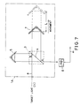
- Fig. 8 shows the arrangement of a main part of the second embodiment in more detail.
- a position detection signal 1 of the movable mirror 7 and a repetitive waveform (interference fringe) signal 2, associated with target light a are respectively input to a data terminal D and a clock terminal CK of a D-type flip-flop 31.
- the signals 1 and 2 are supplied from an interference spectroscopic unit 1 such as a Michelson interferometer through a position detector 18 and an amplifier 19 and through a light receiver 8, an amplifier 9, and a waveform shaping circuit 10, respectively.
- An output signal 3 from an output terminal Q of the D-type flip-flop 31 and the position detection signal 1 are respectively supplied to the first and second input terminals of an exclusive OR gate 32.
- the interference fringe signal 2 and the output signal 3 from the D-type flip-flop 31 are respectively supplied to the first and second input terminals of an AND gate 33.
- An output signal 4 from the AND gate 33 is supplied to an arithmetic circuit 37 including a CPU, a RAM, and the like through an integer counter 13.
- the interference fringe signal 2 and an output signal 5 from the exclusive OR gate 32 are respectively input to a data terminal D and a clock terminal CK of a D-type flip-flop 34.
- the output signal from the exclusive OR gate 32 and a reference clock from a (50-MHz) clock generator 21 are respectively supplied to the first and second input terminals of an AND gate 35.
- An output signal from the AND gate 35 is supplied to the arithmetic circuit 37 through a fraction counter 22a.
- An output signal 6 and the reference clock from the (50-MHz) clock generator 21 are respectively supplied to the first and second input terminals of an AND gate 36.
- An output signal from the AND gate 36 is supplied to the arithmetic circuit 37 through a
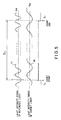
- Fig. 9 shows the relationship in timing between the respective signals 1 to 8 in Fig. 8.
- reference numeral denotes a position detection signal; 2, an interference fringe signal; 3, an output signal from the D-type flip-flop 31; 4, an output signal from the AND gate 33; 5, an output signal from the exclusive OR gate 32; and 6, an output signal from the D-type flip-flop 34.
- an interval associated with counting of a fractional portion at the leading edge of the position detection signal 1, i.e., the interference fringe signal, is represented by A
- an interval associated with counting of a fractional portion at the trailing edge of the signal 1, i.e., the interference fringe signal is represented by C.
- one period associated with the timing at which counting of the output signal 4 from the AND gate 33, i.e., counting of the integral portion of the interference fringe signal, is started is represented by B
- an interval associated with the timing at which the counting operation is ended is represented by D.
- the integer counter 13 outputs a count value Na of the integral portion of the interference fringe signal
- the fraction counter 22a outputs (50-MHz) clock count values N S and N E in the intervals A and C.
- the period counter 23a outputs (50-MHz) clock count values N0 and N1 in the intervals B and D.
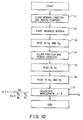
- Fig. 10 is a flow chart of the second embodiment shown in Figs. 8 and 9.
- step S1 the integer counter 13, the fraction counter 22a, and the period counter 23a are cleared.
- step S2 the movable mirror 7 in the interference spectroscopic unit 1 is started. Assume that the target light a is incident on the interference spectroscopic unit 1 at this time.
- step S3 the count value N S of the fraction counter 22 and the count value N0 of the period counter 23a are read in a RAM portion in the arithmetic circuit 37.
- step S4 the counters 22a and 23a are cleared.
- step S5 the count value Na of the integer counter 13 is read in the RAM portion in the arithmetic circuit 37.
- step S6 the count values N E and N1 of the fraction counter 22a and the period counter 23a are read in the RAM portion in the arithmetic circuit 37.
- step S7 the arithmetic circuit 37 executes the following equation on the basis of the value D S stored in the RAM portion in advance and the count values Na, N S , N E , N0, and N1 read in the RAM portion in the above-described manner, thereby calculating the wavelength ⁇ of the target light.
- the denominator of the right-hand side serves to provide a correct interference fringe count N A for the change amount D S of the optical path length, similar to equation (2).
- Fig. 11 shows another relationship in timing for obtaining a fractional value less than a value corresponding to one period at wave count start and end portions. More specifically, in this case, the timings at which the period counter 23a starts counting to obtain the count values N0 and N1 are respectively synchronized with the falling and rising timings of the position detection signal. Counting operations will be sequentially described below.
- N0 N1 can be set, it is only required to obtain either the value N0 or the value N1.
- the fraction counter can obtain the repetitive waveform count of a light intensity signal in a case wherein the movable mirror in the interference spectroscopic unit is moved by a predetermined distance so that the optical path length is changed by the change amount D S .
- the fraction counter can obtain a start fractional value between the count start timing of the wave counter and the timing at which the first count position of repetitive waveforms actually arrives, and can obtain an end fraction value between the count end timing and the timing at which the next count position arrives.
- the period of the repetitive waveforms is obtained by the period counter. Therefore, the ratio of each fractional value to the period, i.e., a fractional value after the decimal point, which is used to correct a previously obtained repetitive waveform count, can be obtained.
- the number of repetitive waveforms of the target light and that of the reference light having the known wavelength are simultaneously counted. Subsequently, the repetitive waveform counts of the target light and the reference light, each having a precision to fractions after the decimal point, can be obtained by the above-described technique. Therefore, the correct wavelength of the target light is calculated on the basis of the wavelength of the reference light and the ratio between the repetitive waveform counts.
- the wavelength measurement precision can be greatly improved as compared with the conventional apparatus in which the repetitive waveform count Na can assume only an integral value.
- the fraction counter is used to count fractional values of the repetitive waveforms (interference fringes) at the count start and end timings together with the integer count for counting the integral value of the repetitive waveforms.
- the light wavelength measuring apparatus of the present invention can measure the wavelength of target light with high precision and high resolution by counting the number of interference fringes of the target light, obtained by the interference spectroscopic unit, including both an integral value and fractional values less than one period, with high precision. Therefore, the apparatus can be applied to various fields, e.g., optical communication apparatuses and optical measurement devices which are reduced in size as much as possible and utilize laser beams.
Landscapes
- Physics & Mathematics (AREA)
- Spectroscopy & Molecular Physics (AREA)
- General Physics & Mathematics (AREA)
- Spectrometry And Color Measurement (AREA)
- Instruments For Measurement Of Length By Optical Means (AREA)
Abstract
Claims (9)
- Appareil de mesure de la longueur d'onde d'un rayon lumineux, destiné à mesurer une longueur d'onde inconnue (λ) d'une lumière cible (a) en utilisant un certain nombre (N) de franges d'interférence produites par la lumière cible (a) quand la longueur d'un trajet optique varie d'une quantité connue (Ds) lors du déplacement continu d'une partie mobile (7) d'une section (1A) de spectroscopie interférentielle, sur laquelle la lumière cible (a) est incidente, à une vitesse constante et sur une distance prédéterminée (L), ladite longueur d'onde inconnue étant déterminée à partir de l'expression mathématique λ = DS/N et ledit appareil comprenant :- un moyen (8) de réception de la lumière, destiné à recevoir une lumière d'interférence provenant de la section (1A) de spectroscopie interférentielle et à convertir la lumière d'interférence reçue en un signal électrique (a₁),- un moyen (18) de détection de la position, destiné à détecter si la partie mobile (7) de la section (1A) de spectroscopie interférentielle se trouve ou non dans une position à l'intérieur d'une plage de déplacement qui correspond à ladite distance prédéterminée (L), et- des moyens de synchronisation (12) destinés à fournir des signaux de démarrage à des moyens de comptage (13, 22a, 23a) pour déterminer le nombre (N) de franges d'interférence,- des moyens (21) de production d'impulsion de référence, destinés à produire une impulsion de référence qui a une fréquence plus élevée que celle des ondes répétitives prédéterminées des franges d'interférence,caractérisé par :- lesdits moyens de synchronisation (12) comprennent une première bascule (31) de type D qui comporte une borne de données, destinée à recevoir un signal de détection de position émis par le moyen (18) de détection de la position; et une borne d'horloge destinée à recevoir le signal électrique de franges d'interférence émis par le moyen (8) de réception de la lumière,- une porte OU exclusif (32) destinée à recevoir le signal de détection de position émis par le moyen (18) de détection de la position et à recevoir un signal de sortie produit par la première bascule (31) de type D,- une première porte ET (33) destinée à recevoir le signal de franges d'interférence provenant du moyen (8) de réception de la lumière et à recevoir le signal de sortie produit par la première bascule (31) de type D,- une seconde bascule (34) de type D comportant une borne de données, destinée à recevoir un signal de sortie produit par la porte OU exclusif (32), et une borne d'horloge destinée à recevoir le signal électrique de franges d'interférence émis par le moyen (8) de réception de la lumière,- une seconde porte ET (35) destinée à recevoir le signal de sortie produit par la porte OU exclusif (32) et à recevoir l'impulsion de référence produite par les moyens (21) de production d'impulsion de référence,- une troisième porte ET (36) destinée à recevoir un signal de sortie produit par la seconde bascule (34) de type D et à recevoir l'impulsion de référence produite par le moyen (21) de production d'impulsion de référence- lesdits moyens de comptage comprennent un compteur de parties entières (13) destiné à compter le nombre de signaux de sortie produits par la première porte ET (23) et à émettre une valeur de comptage (Na) qui correspond au nombre mesuré de parties entières contenues dans le signal électrique de franges d'interférence,- un compteur de parties décimales (22a) destiné à compter le nombre de signaux de sortie produits par la seconde porte ET (35) et à émettre des valeurs de comptage (NS, NE) des impulsions de référence qui correspondent respectivement aux parties décimales lors de la montée et de la chute du signal électrique de franges d'interférence,- un compteur de périodes (23a) destiné à compter le nombre de signaux de sortie produits par la troisième porte ET (36) et à émettre des valeurs de comptage (N0, N1) des impulsions de référence qui correspondent respectivement à des périodes détectées aux instants de début et de fin de la mesure des parties entières du signal électrique de franges d'interférence,ledit appareil comprenant en outre :
- un moyen de calcul (26) destiné à déterminer la longueur d'onde (λ) de la lumière cible en effectuant l'opération arithmétique exprimée par:
- Appareil selon la revendication 1, caractérisé en ce que ledit moyen de calcul contient :- un moyen pour lire, à des premiers instants, les valeurs de comptage (NS, N₀) des impulsions de référence émises par les compteurs de parties décimales et de périodes (22a, 23a),- un moyen pour effacer les compteurs de parties décimales et de périodes (22a, 23a) à des seconds instants, et- un moyen pour lire, à des troisièmes instants, la valeur de comptage (Na) émise par le compteur de parties entières (13) et pour lire, à des quatrièmes instants, les valeurs de comptage (NE, N₁) des impulsions de référence émises par les compteurs de parties décimales et de périodes (22a, 23a).
- Appareil selon la revendication 1 ou 2, caractérisé en ce qu'il comprend en outre un moyen pour calculer la quantité de variation (Ds) de la longueur du trajet optique en effectuant une opération exprimée par :

- Appareil selon la revendication 1 ou 2, caractérisé en ce qu'il comprend en outre un moyen pour calculer la quantité de variation (Ds) de la longueur du trajet optique en effectuant une opération exprimée par :

- Appareil selon l'une des revendications 1 à 3, caractérisé en ce qu'il comprend en outre un moyen pour envoyer la quantité de variation (Ds) de la longueur du trajet optique au moyen de calcul (26) comme une valeur connue.
- Appareil selon la revendication 5, caractérisé en ce qu'il comprend en outre des moyens (25, 27) pour mémoriser la quantité de variation (Ds) de la longueur du trajet optique comme une valeur connue.
- Appareil selon l'une des revendications 1 à 6, caractérisé en ce que ladite section (1A) de spectroscopie interférentielle comprend :- des moyens (3, 4) pour diviser la lumière cible en deux composantes de lumière cible qui se propagent respectivement sur des premier et second trajets optiques,- des moyens fixes de réflexion (5) destinés à réfléchir la composante de lumière cible qui se propage sur le premier trajet optique, et- des moyens mobiles de réflexion (7), constitués par ladite partie mobile, destinés à réfléchir la composante de lumière cible qui se propage sur le second trajet optique tout en se déplaçant simultanément d'une distance prédéterminée,ladite section (1A) de spectroscopie interférentielle émettant des franges d'interférence dues à une interférence entre la lumière réfléchie par les moyens fixes de réflexion et la lumière réfléchie par les moyens mobiles de réflexion (7).
- Appareil selon l'une quelconque des précédentes revendications, caractérisé en ce que ledit moyen (21) de production d'impulsion de référence produit une impulsion de référence d'environ 50 MHz.
- Appareil selon l'une quelconque des précédentes revendications, caractérisé en ce que ladite partie mobile (7) de la section (1A) de spectroscopie interférentielle se déplace d'environ 20 cm.
Applications Claiming Priority (3)
| Application Number | Priority Date | Filing Date | Title |
|---|---|---|---|
| JP2081875A JP2604052B2 (ja) | 1990-03-29 | 1990-03-29 | 光波長測定装置 |
| JP81875/90 | 1990-03-29 | ||
| PCT/JP1991/000385 WO1991014928A1 (fr) | 1990-03-29 | 1991-03-26 | Appareil de mesure de la longeur d'onde d'un rayon lumineux par detection haute precision des franges d'interferences |
Publications (3)
| Publication Number | Publication Date |
|---|---|
| EP0478785A1 EP0478785A1 (fr) | 1992-04-08 |
| EP0478785A4 EP0478785A4 (en) | 1992-07-01 |
| EP0478785B1 true EP0478785B1 (fr) | 1995-06-07 |
Family
ID=13758635
Family Applications (1)
| Application Number | Title | Priority Date | Filing Date |
|---|---|---|---|
| EP91905899A Expired - Lifetime EP0478785B1 (fr) | 1990-03-29 | 1991-03-26 | Appareil de mesure de la longeur d'onde d'un rayon lumineux par detection haute precision des franges d'interferences |
Country Status (5)
| Country | Link |
|---|---|
| US (1) | US5247342A (fr) |
| EP (1) | EP0478785B1 (fr) |
| JP (1) | JP2604052B2 (fr) |
| DE (1) | DE69110230T2 (fr) |
| WO (1) | WO1991014928A1 (fr) |
Cited By (1)
| Publication number | Priority date | Publication date | Assignee | Title |
|---|---|---|---|---|
| DE102008020147A1 (de) * | 2008-04-22 | 2009-10-29 | Carl Zeiss Ag | Verfahren und Vorrichtung zur Bestimmung der m unterschiedlichen Wellenlängen von m optischen Meßstrahlbündeln |
Families Citing this family (8)
| Publication number | Priority date | Publication date | Assignee | Title |
|---|---|---|---|---|
| JPH0719965A (ja) * | 1993-06-30 | 1995-01-20 | Ando Electric Co Ltd | 光波長計 |
| FR2716722B1 (fr) * | 1994-02-25 | 1996-04-05 | France Telecom | Système interférométrique de détection et de localisation de défauts réflecteurs de structures guidant la lumière. |
| JPH07239272A (ja) * | 1994-02-28 | 1995-09-12 | Ando Electric Co Ltd | 光波長計 |
| JPH07270245A (ja) * | 1994-03-31 | 1995-10-20 | Ando Electric Co Ltd | 測長器を用いた光波長計 |
| JPH08101072A (ja) * | 1994-09-30 | 1996-04-16 | Ando Electric Co Ltd | 光波長計 |
| US5959730A (en) * | 1996-11-04 | 1999-09-28 | Ail Systems, Inc. | Apparatus and method for real-time spectral alignment for open-path fourier transform infrared spectrometers |
| US5790250A (en) * | 1996-11-04 | 1998-08-04 | Ail Systems, Inc. | Apparatus and method for real-time spectral alignment for open-path fourier transform infrared spectrometers |
| CN105424185B (zh) * | 2015-11-04 | 2017-08-11 | 清华大学 | 一种计算机辅助的全波段光谱仪波长标定方法 |
Family Cites Families (8)
| Publication number | Priority date | Publication date | Assignee | Title |
|---|---|---|---|---|
| JPS5022422B1 (fr) * | 1969-04-25 | 1975-07-30 | ||
| US4165183A (en) * | 1977-08-26 | 1979-08-21 | The United States Of America As Represented By The Secretary Of Commerce | Fringe counting interferometric system for high accuracy measurements |
| US4413908A (en) * | 1982-03-05 | 1983-11-08 | Bio-Rad Laboratories, Inc. | Scanning interferometer control systems |
| JPS59143933A (ja) * | 1983-02-07 | 1984-08-17 | Pioneer Electronic Corp | 半導体レ−ザの特性測定装置 |
| US4847878A (en) * | 1988-03-31 | 1989-07-11 | Nicolet Instrument Corporation | Method and apparatus for determining mirror position in a fourier-transform infrared spectrometer |
| US4999586A (en) * | 1988-05-26 | 1991-03-12 | North American Philips Corp | Wideband class AB CRT cathode driver |
| JPH0249169A (ja) * | 1988-08-11 | 1990-02-19 | Anritsu Corp | アラン分散測定器 |
| JP2597080Y2 (ja) * | 1993-09-01 | 1999-06-28 | 株式会社山本製作所 | 農園芸用の育苗ポット |
-
1990
- 1990-03-29 JP JP2081875A patent/JP2604052B2/ja not_active Expired - Fee Related
-
1991
- 1991-03-26 WO PCT/JP1991/000385 patent/WO1991014928A1/fr not_active Ceased
- 1991-03-26 EP EP91905899A patent/EP0478785B1/fr not_active Expired - Lifetime
- 1991-03-26 US US07/777,371 patent/US5247342A/en not_active Expired - Lifetime
- 1991-03-26 DE DE69110230T patent/DE69110230T2/de not_active Expired - Fee Related
Cited By (1)
| Publication number | Priority date | Publication date | Assignee | Title |
|---|---|---|---|---|
| DE102008020147A1 (de) * | 2008-04-22 | 2009-10-29 | Carl Zeiss Ag | Verfahren und Vorrichtung zur Bestimmung der m unterschiedlichen Wellenlängen von m optischen Meßstrahlbündeln |
Also Published As
| Publication number | Publication date |
|---|---|
| DE69110230D1 (de) | 1995-07-13 |
| DE69110230T2 (de) | 1996-03-07 |
| JP2604052B2 (ja) | 1997-04-23 |
| EP0478785A1 (fr) | 1992-04-08 |
| WO1991014928A1 (fr) | 1991-10-03 |
| US5247342A (en) | 1993-09-21 |
| JPH03279828A (ja) | 1991-12-11 |
| EP0478785A4 (en) | 1992-07-01 |
Similar Documents
| Publication | Publication Date | Title |
|---|---|---|
| GB1603155A (en) | Apparatus and method for determination of wavelength | |
| JPH0277672A (ja) | 遅延時間測定装置 | |
| EP0478785B1 (fr) | Appareil de mesure de la longeur d'onde d'un rayon lumineux par detection haute precision des franges d'interferences | |
| EP1808671B1 (fr) | Dispositif de mesure de différence de temps, méthode de mesure, dispositif de mesure de distance et méthode de mesure de distance | |
| EP0250764B1 (fr) | Procédé de mesure de l'épaisseur de pellicules et appareil à cet effet | |
| US4678337A (en) | Laser based gaging system and method of using same | |
| JPS636483A (ja) | 時間間隔測定装置 | |
| US5249030A (en) | Method and apparatus for determining the position of a moving body and the time of the position measurement | |
| EP0219127B1 (fr) | Méthode et appareil pour mesurer un déplacement | |
| US4332475A (en) | Edge timing in an optical measuring apparatus | |
| US5576834A (en) | Optical wavemeter utilizing numerical fraction difference of pulses for determining absolute wave length | |
| RU2112208C1 (ru) | Устройство для автоматизированного измерения угловых величин | |
| JP3374550B2 (ja) | 光波長計 | |
| JP2543059B2 (ja) | トラッキングデ−タ抽出方法 | |
| JPS6324110A (ja) | 光学式位置検出装置 | |
| JP2667501B2 (ja) | レーザ距離測定装置 | |
| JPH0413905A (ja) | レーザ測長器の干渉縞計数回路 | |
| JP3312666B2 (ja) | レーザ測距装置用信号処理回路 | |
| JPH02272310A (ja) | 回転角度測定装置 | |
| SU1485089A1 (ru) | Способ градуировки скоростной шкапы мессбауэровского спектрометра | |
| SU847033A1 (ru) | Компаратор дл поверки штриховыхМЕР | |
| SU714880A1 (ru) | Радиационный измеритель толщиныллиСТОВ | |
| JPH0244173Y2 (fr) | ||
| SU970309A1 (ru) | Сравнивающее устройство | |
| GB2208924A (en) | Method of calibration of the velocity scale of a Mössbauer spectrometer |
Legal Events
| Date | Code | Title | Description |
|---|---|---|---|
| PUAI | Public reference made under article 153(3) epc to a published international application that has entered the european phase |
Free format text: ORIGINAL CODE: 0009012 |
|
| 17P | Request for examination filed |
Effective date: 19911129 |
|
| AK | Designated contracting states |
Kind code of ref document: A1 Designated state(s): DE FR GB |
|
| A4 | Supplementary search report drawn up and despatched |
Effective date: 19920508 |
|
| AK | Designated contracting states |
Kind code of ref document: A4 Designated state(s): DE FR GB |
|
| 17Q | First examination report despatched |
Effective date: 19931025 |
|
| GRAA | (expected) grant |
Free format text: ORIGINAL CODE: 0009210 |
|
| AK | Designated contracting states |
Kind code of ref document: B1 Designated state(s): DE FR GB |
|
| ET | Fr: translation filed | ||
| REF | Corresponds to: |
Ref document number: 69110230 Country of ref document: DE Date of ref document: 19950713 |
|
| PLBE | No opposition filed within time limit |
Free format text: ORIGINAL CODE: 0009261 |
|
| STAA | Information on the status of an ep patent application or granted ep patent |
Free format text: STATUS: NO OPPOSITION FILED WITHIN TIME LIMIT |
|
| 26N | No opposition filed | ||
| REG | Reference to a national code |
Ref country code: GB Ref legal event code: IF02 |
|
| PGFP | Annual fee paid to national office [announced via postgrant information from national office to epo] |
Ref country code: GB Payment date: 20020327 Year of fee payment: 12 |
|
| PGFP | Annual fee paid to national office [announced via postgrant information from national office to epo] |
Ref country code: FR Payment date: 20021128 Year of fee payment: 13 |
|
| PG25 | Lapsed in a contracting state [announced via postgrant information from national office to epo] |
Ref country code: GB Free format text: LAPSE BECAUSE OF NON-PAYMENT OF DUE FEES Effective date: 20030326 |
|
| PGFP | Annual fee paid to national office [announced via postgrant information from national office to epo] |
Ref country code: DE Payment date: 20030527 Year of fee payment: 13 |
|
| GBPC | Gb: european patent ceased through non-payment of renewal fee |
Effective date: 20030326 |
|
| PG25 | Lapsed in a contracting state [announced via postgrant information from national office to epo] |
Ref country code: DE Free format text: LAPSE BECAUSE OF NON-PAYMENT OF DUE FEES Effective date: 20041001 |
|
| PG25 | Lapsed in a contracting state [announced via postgrant information from national office to epo] |
Ref country code: FR Free format text: LAPSE BECAUSE OF NON-PAYMENT OF DUE FEES Effective date: 20041130 |
|
| REG | Reference to a national code |
Ref country code: FR Ref legal event code: ST |