EP0484155A2 - Tandem roller pipe bender - Google Patents
Tandem roller pipe bender Download PDFInfo
- Publication number
- EP0484155A2 EP0484155A2 EP91310063A EP91310063A EP0484155A2 EP 0484155 A2 EP0484155 A2 EP 0484155A2 EP 91310063 A EP91310063 A EP 91310063A EP 91310063 A EP91310063 A EP 91310063A EP 0484155 A2 EP0484155 A2 EP 0484155A2
- Authority
- EP
- European Patent Office
- Prior art keywords
- bending
- pipe
- former
- axis
- arm
- Prior art date
- Legal status (The legal status is an assumption and is not a legal conclusion. Google has not performed a legal analysis and makes no representation as to the accuracy of the status listed.)
- Granted
Links
- 238000005452 bending Methods 0.000 claims abstract description 69
- 238000006243 chemical reaction Methods 0.000 claims description 13
- 238000003462 Bender reaction Methods 0.000 description 7
- 239000000463 material Substances 0.000 description 6
- 238000000034 method Methods 0.000 description 4
- 229910000831 Steel Inorganic materials 0.000 description 3
- 239000010959 steel Substances 0.000 description 3
- 210000002969 egg yolk Anatomy 0.000 description 2
- 239000012530 fluid Substances 0.000 description 2
- 230000002093 peripheral effect Effects 0.000 description 2
- 238000005096 rolling process Methods 0.000 description 2
- 230000037303 wrinkles Effects 0.000 description 2
- 239000012141 concentrate Substances 0.000 description 1
- 238000010276 construction Methods 0.000 description 1
- 230000007547 defect Effects 0.000 description 1
- 230000006698 induction Effects 0.000 description 1
- 230000000750 progressive effect Effects 0.000 description 1
- 230000000630 rising effect Effects 0.000 description 1
- 230000000007 visual effect Effects 0.000 description 1
- 238000011179 visual inspection Methods 0.000 description 1
- 238000003466 welding Methods 0.000 description 1
- 230000037373 wrinkle formation Effects 0.000 description 1
Images


Classifications
-
- B—PERFORMING OPERATIONS; TRANSPORTING
- B21—MECHANICAL METAL-WORKING WITHOUT ESSENTIALLY REMOVING MATERIAL; PUNCHING METAL
- B21D—WORKING OR PROCESSING OF SHEET METAL OR METAL TUBES, RODS OR PROFILES WITHOUT ESSENTIALLY REMOVING MATERIAL; PUNCHING METAL
- B21D7/00—Bending rods, profiles, or tubes
- B21D7/02—Bending rods, profiles, or tubes over a stationary forming member; by use of a swinging forming member or abutment
- B21D7/024—Bending rods, profiles, or tubes over a stationary forming member; by use of a swinging forming member or abutment by a swinging forming member
-
- B—PERFORMING OPERATIONS; TRANSPORTING
- B21—MECHANICAL METAL-WORKING WITHOUT ESSENTIALLY REMOVING MATERIAL; PUNCHING METAL
- B21D—WORKING OR PROCESSING OF SHEET METAL OR METAL TUBES, RODS OR PROFILES WITHOUT ESSENTIALLY REMOVING MATERIAL; PUNCHING METAL
- B21D7/00—Bending rods, profiles, or tubes
- B21D7/06—Bending rods, profiles, or tubes in press brakes or between rams and anvils or abutments; Pliers with forming dies
- B21D7/063—Pliers with forming dies
Definitions
- the invention pertains to pipe bending and more particularly to an apparatus and method for bending pipe using at least two means for exerting pressure against an inside former.
- Severe kinking is usually experienced with C350 grade pipe in conventional formers with a radius of bend of approximately three times the diameter of the pipe. There have been attempts to avoid this by increasing the former radius from three diameters to four diameters and by making the former tighter on the pipe, even to the point of having the pipe squeeze into the former. It is intended that this grip in the former will stop the pipe rising out of the former at the point of bend and allow a kink to form. These measures are successful on some types of pipe and in most cases kinking is not found while flattening and wrinkling are only minor.
- draw benders Certain more effective and also more complex and expensive benders are referred to as draw benders. They are arranged to start the bend at a predetermined point and progressively bend this section around a former in one direction only. This is usually done by providing a fixed inside former, with one reaction point also fixed. Bending is achieved by a sliding or rolling outside former following an arc concentric with the inside former's shape. This allows the reaction point to be kept relatively close to the actual point of bend at all times and high former contact pressure is maintained. This tends to minimise wrinkling. However, with some extra light wall sections, wrinkling is still encountered with considarably flattening around the outside of the bend.
- Draw benders are usually arranged to make a bend progressively in one direction from a start point, by engaging the pipe to be bent between a fixed reaction point, a fixed inside former and a movable outside member which is attached pivotally at the centre of the fixed former.
- Some variations use a fixed outside member and an inside former and clamping reaction member that rotate together pulling the pipe around the bend.
- the outside member On fixed inside former types the outside member is usually a shaped roller that moves at a constant radius to the fixed inside former which has a curved groove to shape and support the pipe as it is bent. Sometimes the outside member is a flat roller with a shaped straight outside former to distribute the bending force over a length of the pipe to avoid deformation of the pipe surface by a concentrated point of contact from a roller alone.
- the pipe can be slid between the three members but this is very awkward, even impossible if a series of bends are to be made on one pipe close to each other.
- the outside member is moved away from the former far enough to allow the pipe to be lowered to the plane of bending and moved into the former groove. Then the outside member must be moved closer to the former again for bending. After bending the outside member must be moved away again to unload the pipe.
- This movement is usually achieved by mounting the outside member in a carriage which has its position adjusted along the radial arm by a screw thread and handle.
- This means can introduce two problems; that it is awkwardly slow to operate, and that it does not accurately bring the outside member to the same radial position for all bends in a series of bends that may be required to be the same.
- the carriage is moved radially in relation to the former by a hydraulic cylinder or other linear actuator. This is very expensive to arrange and physically large, making such benders only suitable for industry producing large volume runs of products using bent pipe.
- a pipe bender comprising: a base; a former mounted on the base and having a former surface extending angularly at a fixed radius about a bending axis, said former surface being provided to engage a length of pipe to be bent to conform to at least a portion of the length of said former surface; a bending arm pivotally mounted on said base for pivotting movement about said axis; a bending assembly mounted on said arm, said assembly including two deforming rollers rotatably mounted for movement about an axes parallel to said bending axis, and spaced radially outwardly of said surface, said rollers being adapted to engage said length of pipe to cause bending thereof as it is moved angularly about said axis; said rollers being substantially co-extensive with one roller being positioned radially with respect to said bending axis so that in use said one roller is positioned at approximately the bending point of the pipe, the other roller being spaced angularly forward of said one roller and radially further from
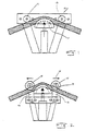
- a conventional fixed post bender 10 uses a rigid, curved former 11 which controls both the cross-sectional profile of the section and the radius of the bend. Fixed posts 12 are set apart while the former 11 is forced into the section between the posts to create the bend.
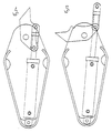
- Fig. 2 illustrates a variant of a conventional fixed post bender which allows the reaction points 13 to be kept fairly close to the point of the bend while also allowing them to move outwards (in the direction of the arrows 14) as bending progresses. This is done by mounting rollers 15 on each of two pivotted arms 16.
- Fig. 3 illustrates a prior art induction bender 20. A fixed inside former 21 cooperates with a sliding or rolling outside former 22.
- an inside former 50 includes a peripheral channel 51 which conforms to the shape of the section 52 being bent.
- the section 52 will be a round pipe and the cross-section of the channel 51 will correspond to about one half of the circumference of the pipe.
- teachings of the present invention are not limited to bending of round pipes.
- the inside former 50 works in cooperation with an outside former 53.
- the outside former 53 comprises at least two means for exerting pressure on the section 52.
- the means for exerting pressure are rollers 54.
- the means need not be rollers, as sliding shoes or various other pressure exerting devices could be used in place of the rollers 54.
- the rollers 54 are mounted on a pivotting cradle 55.
- the cradle 55 pivots about an axis 56.
- the rollers 54 have concave peripheral grooves or channels which match the profile of the section being bent. Because the cradle is pivotting, the reaction force exerted against the first roller 57 is reflected or transmitted to the second roller 58 which is located at or near the point of bend.
- leading outside former 57 applies the bending force as a moment and that the trailing outside former 58 applies a force to the material to contain and control the shape of material in the inside former 50. It is preferred that the trailing outside former 58 be located at or near the point of bend. The trailing outside former 58 need not be located precisely at the point of bend. In a preferred embodiment, a gap of several millimeters is left between the outside diameter of the trailing former and the outside diameter of the inside former. This ensures that the pressure exerted by the trailing edge former is also exerted onto the section or pipe being bent and not transmitted directly onto the inside former.
- the distance separating the two outside formers could vary greatly so that the contact they have with the material being bent could be very close or quite distant.
- the two outside formers while preferably mounted on a common pivotting carriage, could be moved into and out of position by separate means. Hydraulic, pneumatic, electrical, magnetic or mechanical devices can be used to move each outside former into and out of position independent of the other outside formers.
- the pivot point 56 of the carriage 55 can be moved relative to the rotational centres of the outside formers to as to vary the geometry and hence the contact pressure exerted by the trailing outside former 58.
- rollers and cradle 55 rotate with respect to the centre of the inside former or whether the former and section being bent rotate with respect to a fixed set of outside formers.
- rollers or other means for exerting pressure may be mounted on a rotating arm or urged into position in other suitable ways.
- two pairs of outside formers could be located to allow bending to proceed around the inside former in opposite directions and simultaneously.
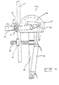
- Fig. 6 illustrates an example of a pipe bending apparatus 60 utilizing tandem rollers 61 as disclosed with reference to Fig. 5.
- the rollers 62 are mounted on a common cradle 63 which rotates about a pivot point 64.
- the cradle 63 pivots with respect to an arm 65 which rotates about the centre 66 of the inside former 67.
- a central post 68 to which the inside former is mounted also bears an arm 69 which provides a fixed reaction point 70 for the material which is being bent 71.
- a hydraulic cylinder 72 in combination with a link mechanism 73 allows the arm 65 to be rotated at least 180° with respect to the inside former. This particular arrangement for rotating the arm 65 is described more completely in Australian Patent Application No. 58906/90.
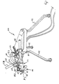
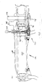
- FIG. 7 to 13 of the accompanying drawings there is schematically depicted a pipe bender 110.
- the bender 110 has a base 111 from which there extends legs 112 to support the base 111 on a ground surface.
- the base 111 is basically a hollow housing which pivotally supports an arm 113 for pivotting movement about a generally vertical axis defined by the main pin 114.
- a bending assembly 115 which includes a carriage 116.
- the carriage 116 is slidably mounted on the arm 113 for longitudinal movement relative thereto. This movement is effected by means of a threaded shaft 117 provided at its outer end with an adjustment wheel or lever 118.
- the shaft 117 threadably engages a threaded passage 119 formed in the arm 113.
- the bending assembly 115 further includes a roller support 120 pivotally mounted by means of a secondary pin 140.
- the support 120 co-operates with a pair of vertically spaced generally horizontal flanges 121 to support two or more rollers.
- two rollers 122 and 123 are provided.
- the flanges 121 are joined by means of a handle 124 which is pivotally supported by passing through a passage in the support 120.
- the rollers are each supported by means of a pin 125.
- the roller 122 is positioned at the point of bending and the roller 123 is positioned forward thereof.
- the roller 123 is located angularly forward of and radially further out than the roller 122, relative to the bending axis.
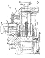
- a hydraulic ram 126 having a cylinder 127 pivotally mounted at one end by means of a pin 145.
- the ram 126 has a piston rod 129 terminating with a yolk 128.
- the yolk 128 is pivotally attached to a link 129 by means of a pin 130.
- the other end of the link 129 is pivotally attached to the arm 113 by means of a pin 131.
- the arm 113 is also provided with a socket 146 which receives the pin 130 during various phases of movement of the arm 113 about the pin 114.
- a former 132 which is provided with a former surface 133 which extends angularly about the pin 114, at a generally constant radius.
- the former surface 132 is concave in transverse cross-section.
- a length of pipe 134 to be deformed by the bender 110 is bended to generally conform to the surface 132 and therefore the pin 114 also defines the bending axis about which the pipe 134 is bent.
- the hydraulic ram 126 is controlled in its movement by means of a spool valve 135, operated by means of a lever 136 extending upwardly through the base 111.
- the spool valve 135 receives hydraulic fluid under pressure and delivers it to the cylinder 127.
- hydraulic fluid under pressure is delivered to the cylinder 127 to cause the piston rod 129 to telescopically extend from within the cylinder 127.
- This telescopic movement commenced from when the hydraulic ram 126 is configured as shown in Figure 4.
- the arm 113 is caused to pivot due to engagement of the pin 130 with the socket 132. This continues until the arm 113 has reached the position depicted in Figure 6. At this position, the arm 113 pivots to remove the pin 130 from contact within the socket 146. However the arm 113 continues to pivot due to the force being applied to the arm 113 via the link 129.
- the spool valve 135 has a cam follower 136 which engages a cam 137 fixed to the arm 113 (via the pin 125) so as to rotate with the arm 113.
- the cam 137 is adjustable to return the spool valve 135 to the start position and/or to cause the spool valve 135 to return the arm 113 to the start position. Accordingly, the cam 137 can be used to govern the angle through which the pipe 134 is bent.
- the former 132 is mounted on the pin 114 but is removable. This enables formers of various sizes to be used so that varying radii may be produced.
- the former 132 has a rear recess 139 which engages a projection 140 on the base 111, so that the former 132 is held stationary during operation.
- a pipe support 141 which engages the pipe 134 to retain one portion stationary with respect to the base 111 during bending.
- the bender 110 is described as bending in one predetermined direction. However it should be appreciated that bending can take place in the reverse direction. This is achieved by removing the former 132. Thereafter, the lever 136 is removed together with the cam 137 by release of the bolt 138. The handle 118 is then rotated to remove the bending assembly 115. Next the main pin 114 is removed which enables the arm 113 to be pulled from within the base 111. This is achieved by telescopic movement of the piston rod 127 outwardly with respect to the cylinder 127. Thereafter, the arm 113, link 129 and piston rod 127 are rotated about the axis of the piston rod 127, through 180°.
- the handle 118 is rotated in order to move the rollers 122 radially with respect to the pin 114, in order to accomodate pipes of different diameters. It should further be appreciated that two or more rollers 122 may be employed, with one of the rollers being positioned at the point of deformation of the pipe 134.
Landscapes
- Engineering & Computer Science (AREA)
- Mechanical Engineering (AREA)
- Bending Of Plates, Rods, And Pipes (AREA)
- Machines For Manufacturing Corrugated Board In Mechanical Paper-Making Processes (AREA)
Abstract
Description
- The invention pertains to pipe bending and more particularly to an apparatus and method for bending pipe using at least two means for exerting pressure against an inside former.
- There are many known apparatuses for pipe bending, each with its own particular method of use and each with its own limitations. Certain features are commonly considered to be unacceptable in a bent section of pipe. Kinking of the surface of the section is usually found on the inside of the bend. It is considered a major fault. Wrinkling of the surface of this section is also usually found on the inside of a bend. Wrinkling is like small but repeated kinks and is often not acceptable. Distortion of the original shape of the cross-sectional profile in the form of a flattening found at the outside of the bend is sometimes acceptable if only minor by visual inspection. Marks, dents or bulges left in the surface of the section by the bending apparatus is usually considered a minor fault from a mechanical standpoint but may be very significant in a visual sense.
- In recent times, pipe and RHS have been available in C350 grade steel, which is stronger than previously supplied steels. This grade of steel is work hardened when it is cold formed into pipe. It is also welded at the seam by electric resistance welding. The resulting pipe and RHS section is stronger and much more resistant to deformation. However bending is itself a form of controlled deformation. Further, sections are now offered with thinner wall thicknesses to give a section of similar strength lower weight than previous sections. While the strength, section thinness and lower weight may be advantagous to most users, problems involving all of the bending faults mentioned above are encountered when using conventional bending devices which were designed for sections produced by prior means.
- Most existing pipe benders use a rigid, curved former which controls both the cross-sectional profile of the section and the radius of the bend. One simple type of bender users two fixed posts to apply a reaction force, while the inner former is forced into the pipe section between the posts to create the bend. The bend starts at the centre and progresses in both directions along the section as the former is progressively advanced between the posts. This type of bender is usually referred to as a "fixed post bender". Because the reaction points are widely spaced (to allow the former to pass between them) the force applied is relatively low allowing easy bending. However, high former contact pressure is desireable to prevent wrinkling of the bend, particularly with C350 grade sections which are in use today. Severe kinking is usually experienced with C350 grade pipe in conventional formers with a radius of bend of approximately three times the diameter of the pipe. There have been attempts to avoid this by increasing the former radius from three diameters to four diameters and by making the former tighter on the pipe, even to the point of having the pipe squeeze into the former. It is intended that this grip in the former will stop the pipe rising out of the former at the point of bend and allow a kink to form. These measures are successful on some types of pipe and in most cases kinking is not found while flattening and wrinkling are only minor.
- However, many users do not like the swept band appearance of a four diameter bend as it affects design from both a mechanical point of view as well as aesthetic considerations. Also, variations in pipe quality, bending technique and former specifications all cause serious bending faults.
- A fairly recent variation of the fixed post bender allows the reaction points to be kept fairly close to the point of bend while also providing for them to move outward as bending progresses. This is done by mounting a roller on each of two pivotting arms. The arms move apart as the former is driven between them. However, this method still results in some problems with extra light wall sections where some wrinkling still occurs and outside flattening is noticeable.
- Certain more effective and also more complex and expensive benders are referred to as draw benders. They are arranged to start the bend at a predetermined point and progressively bend this section around a former in one direction only. This is usually done by providing a fixed inside former, with one reaction point also fixed. Bending is achieved by a sliding or rolling outside former following an arc concentric with the inside former's shape. This allows the reaction point to be kept relatively close to the actual point of bend at all times and high former contact pressure is maintained. This tends to minimise wrinkling. However, with some extra light wall sections, wrinkling is still encountered with considarably flattening around the outside of the bend.
- Draw benders are usually arranged to make a bend progressively in one direction from a start point, by engaging the pipe to be bent between a fixed reaction point, a fixed inside former and a movable outside member which is attached pivotally at the centre of the fixed former. Some variations use a fixed outside member and an inside former and clamping reaction member that rotate together pulling the pipe around the bend.
- On fixed inside former types the outside member is usually a shaped roller that moves at a constant radius to the fixed inside former which has a curved groove to shape and support the pipe as it is bent. Sometimes the outside member is a flat roller with a shaped straight outside former to distribute the bending force over a length of the pipe to avoid deformation of the pipe surface by a concentrated point of contact from a roller alone.
- To load the pipe into the bender ready for bending the pipe can be slid between the three members but this is very awkward, even impossible if a series of bends are to be made on one pipe close to each other. For ease of use the outside member is moved away from the former far enough to allow the pipe to be lowered to the plane of bending and moved into the former groove. Then the outside member must be moved closer to the former again for bending. After bending the outside member must be moved away again to unload the pipe.
- This movement is usually achieved by mounting the outside member in a carriage which has its position adjusted along the radial arm by a screw thread and handle. This means can introduce two problems; that it is awkwardly slow to operate, and that it does not accurately bring the outside member to the same radial position for all bends in a series of bends that may be required to be the same. In some industrial bending apparatus the carriage is moved radially in relation to the former by a hydraulic cylinder or other linear actuator. This is very expensive to arrange and physically large, making such benders only suitable for industry producing large volume runs of products using bent pipe.
- It is an object of the invention to substantially ameliorate some of the disadvantages associated with prior art pipe benders.
- There is disclosed herein a pipe bender comprising:
a base;
a former mounted on the base and having a former surface extending angularly at a fixed radius about a bending axis, said former surface being provided to engage a length of pipe to be bent to conform to at least a portion of the length of said former surface;
a bending arm pivotally mounted on said base for pivotting movement about said axis;
a bending assembly mounted on said arm, said assembly including two deforming rollers rotatably mounted for movement about an axes parallel to said bending axis, and spaced radially outwardly of said surface, said rollers being adapted to engage said length of pipe to cause bending thereof as it is moved angularly about said axis;
said rollers being substantially co-extensive with one roller being positioned radially with respect to said bending axis so that in use said one roller is positioned at approximately the bending point of the pipe, the other roller being spaced angularly forward of said one roller and radially further from said bending axis than said one roller; and
motor means to cause angular movement of said arm about said axis to thereby move said roller to deform said pipe. - A preferred form of the present invention will now be described by way of example with reference to the accompanying drawings wherein:
- Figure 1 is a front elevation of a prior art fixed post bender;
- Figure 2 is a front elevation of a prior art bender with pivotted arms;
- Figure 3 is a front elevation of a prior art draw bender;
- Figure 4 is a front elevation illustrating a source of defects in conventional pipe benders;
- Figure 5 is a front elevation of a tandem roller pipe bender according to the teachings of the present invention;
- Figure 6 is a front elevation of a bending apparatus incorporating a tandem roller arrangement;
- Figure 7 is a schematic perspective view of a pipe bender;
- Figure 8 is a schematic sectioned side elevation of a portion of the pipe bender of Figure 7;
- Figure 9 is a schematic sectioned side elevation of the pipe bender of Figure 7; and
- Figures 10 to 13 are schematic plan views of the pipe bender of Figure 7 in progressive modes of operation.
- As shown in Fig. 1, a conventional fixed post bender 10 uses a rigid, curved former 11 which controls both the cross-sectional profile of the section and the radius of the bend.
Fixed posts 12 are set apart while the former 11 is forced into the section between the posts to create the bend. Fig. 2 illustrates a variant of a conventional fixed post bender which allows the reaction points 13 to be kept fairly close to the point of the bend while also allowing them to move outwards (in the direction of the arrows 14) as bending progresses. This is done by mountingrollers 15 on each of twopivotted arms 16. Fig. 3 illustrates a priorart induction bender 20. A fixed inside former 21 cooperates with a sliding or rolling outside former 22. Each of these prior devices has been briefly described and their limitations partially discussed in the BACKGROUND OF THE INVENTION. It is believed that wrinkling occurs in these and other devices because the actual point of bend can lag behind the point of maximum contact pressure. This causes the pipe or section being formed to be lifted out of the inside former by leverage from the reaction point and the point of maximum contact pressure. This concentrates the bend momentarily until a new bend point is established at the contact point. The cycle continues, thus causing wrinkles. This is shown in Fig. 4, wherein A represents the reaction point, B represents the point of maximum contact pressure and C represents the point of bending. - It is possible to avoid the cycle of wrinkle formation by providing a second point of contact pressure at the point of bend. A device for achieving this result is illustrated in Fig. 5. As shown in Fig. 5, an inside former 50 includes a
peripheral channel 51 which conforms to the shape of thesection 52 being bent. Generally, thesection 52 will be a round pipe and the cross-section of thechannel 51 will correspond to about one half of the circumference of the pipe. However, it should be appreciated that the teachings of the present invention are not limited to bending of round pipes. - The inside former 50 works in cooperation with an outside former 53. The outside former 53 comprises at least two means for exerting pressure on the
section 52. For the purpose of the present example, the means for exerting pressure arerollers 54. However, the means need not be rollers, as sliding shoes or various other pressure exerting devices could be used in place of therollers 54. Therollers 54 are mounted on apivotting cradle 55. Thecradle 55 pivots about an axis 56. Preferably, therollers 54 have concave peripheral grooves or channels which match the profile of the section being bent. Because the cradle is pivotting, the reaction force exerted against thefirst roller 57 is reflected or transmitted to thesecond roller 58 which is located at or near the point of bend. This keeps the pipe or material at the point of bend fully seated in the inside former 50, thus prevent the point of bend from lagging the point of maximum pressure. Thus, bending will be continuous without the wrinkle cycle being encountered. One advantage of this system is that the grip of the inside former 50 is not relied upon to keep the material at the point of bend seated. Because former squeeze is not required, the profile shape of the formers is less critical. By reducing the inside former coverage to one half pipe diameter and having the point of bend outside former 54 with half pipe diameter coverage also, the profile of the pipe will be fully contained at the point of bend and outside flattening will be minimized. This allows former radius to be reduced while maintaining a good quality of bend on a wide range of sections. - It can be appreciated that the leading outside former 57 applies the bending force as a moment and that the trailing outside former 58 applies a force to the material to contain and control the shape of material in the inside former 50. It is preferred that the trailing outside former 58 be located at or near the point of bend. The trailing outside former 58 need not be located precisely at the point of bend. In a preferred embodiment, a gap of several millimeters is left between the outside diameter of the trailing former and the outside diameter of the inside former. This ensures that the pressure exerted by the trailing edge former is also exerted onto the section or pipe being bent and not transmitted directly onto the inside former.
- The distance separating the two outside formers could vary greatly so that the contact they have with the material being bent could be very close or quite distant. Further, the two outside formers, while preferably mounted on a common pivotting carriage, could be moved into and out of position by separate means. Hydraulic, pneumatic, electrical, magnetic or mechanical devices can be used to move each outside former into and out of position independent of the other outside formers. In this regard it should also be noted that the pivot point 56 of the
carriage 55 can be moved relative to the rotational centres of the outside formers to as to vary the geometry and hence the contact pressure exerted by the trailing outside former 58. - It should be appreciated that the advantages of the present invention are obtained regardless of whether the rollers and
cradle 55 rotate with respect to the centre of the inside former or whether the former and section being bent rotate with respect to a fixed set of outside formers. Similarly the rollers or other means for exerting pressure may be mounted on a rotating arm or urged into position in other suitable ways. - To speed the rate at which sections can be bent, two pairs of outside formers could be located to allow bending to proceed around the inside former in opposite directions and simultaneously.
- Fig. 6 illustrates an example of a
pipe bending apparatus 60 utilizing tandem rollers 61 as disclosed with reference to Fig. 5. Note that therollers 62 are mounted on acommon cradle 63 which rotates about a pivot point 64. Thecradle 63 pivots with respect to anarm 65 which rotates about the centre 66 of the inside former 67. Acentral post 68 to which the inside former is mounted also bears anarm 69 which provides a fixedreaction point 70 for the material which is being bent 71. Ahydraulic cylinder 72 in combination with alink mechanism 73 allows thearm 65 to be rotated at least 180° with respect to the inside former. This particular arrangement for rotating thearm 65 is described more completely in Australian Patent Application No. 58906/90. - In Figures 7 to 13 of the accompanying drawings there is schematically depicted a pipe bender 110. The bender 110 has a base 111 from which there extends
legs 112 to support the base 111 on a ground surface. The base 111 is basically a hollow housing which pivotally supports anarm 113 for pivotting movement about a generally vertical axis defined by themain pin 114. - Mounted on the radial extremity of the
arm 113 is a bendingassembly 115 which includes acarriage 116. Thecarriage 116 is slidably mounted on thearm 113 for longitudinal movement relative thereto. This movement is effected by means of a threadedshaft 117 provided at its outer end with an adjustment wheel orlever 118. Theshaft 117 threadably engages a threaded passage 119 formed in thearm 113. - The bending
assembly 115 further includes aroller support 120 pivotally mounted by means of asecondary pin 140. Thesupport 120 co-operates with a pair of vertically spaced generallyhorizontal flanges 121 to support two or more rollers. In this particular embodiment tworollers 122 and 123 are provided. Theflanges 121 are joined by means of ahandle 124 which is pivotally supported by passing through a passage in thesupport 120. The rollers are each supported by means of apin 125. - The roller 122 is positioned at the point of bending and the
roller 123 is positioned forward thereof. Theroller 123 is located angularly forward of and radially further out than the roller 122, relative to the bending axis. - Mounted within the base 111 is a
hydraulic ram 126 having acylinder 127 pivotally mounted at one end by means of apin 145. Theram 126 has apiston rod 129 terminating with ayolk 128. Theyolk 128 is pivotally attached to alink 129 by means of apin 130. The other end of thelink 129 is pivotally attached to thearm 113 by means of apin 131. Thearm 113 is also provided with asocket 146 which receives thepin 130 during various phases of movement of thearm 113 about thepin 114. - Also mounted on the base 111 is a former 132 which is provided with a
former surface 133 which extends angularly about thepin 114, at a generally constant radius. In this particular embodiment, theformer surface 132 is concave in transverse cross-section. In this regard it should be appreciated that a length of pipe 134 to be deformed by the bender 110, is bended to generally conform to thesurface 132 and therefore thepin 114 also defines the bending axis about which the pipe 134 is bent. - The
hydraulic ram 126 is controlled in its movement by means of aspool valve 135, operated by means of alever 136 extending upwardly through the base 111. Thespool valve 135 receives hydraulic fluid under pressure and delivers it to thecylinder 127. When thespool valve 135 is moved in a first direction by means of thelever 136, hydraulic fluid under pressure is delivered to thecylinder 127 to cause thepiston rod 129 to telescopically extend from within thecylinder 127. This telescopic movement commenced from when thehydraulic ram 126 is configured as shown in Figure 4. As thepiston rod 127 extends, thearm 113 is caused to pivot due to engagement of thepin 130 with thesocket 132. This continues until thearm 113 has reached the position depicted in Figure 6. At this position, thearm 113 pivots to remove thepin 130 from contact within thesocket 146. However thearm 113 continues to pivot due to the force being applied to thearm 113 via thelink 129. - The
spool valve 135 has acam follower 136 which engages acam 137 fixed to the arm 113 (via the pin 125) so as to rotate with thearm 113. Thecam 137 is adjustable to return thespool valve 135 to the start position and/or to cause thespool valve 135 to return thearm 113 to the start position. Accordingly, thecam 137 can be used to govern the angle through which the pipe 134 is bent. - The former 132 is mounted on the
pin 114 but is removable. This enables formers of various sizes to be used so that varying radii may be produced. The former 132 has arear recess 139 which engages aprojection 140 on the base 111, so that the former 132 is held stationary during operation. - Also mounted on the base 111 is a pipe support 141 which engages the pipe 134 to retain one portion stationary with respect to the base 111 during bending.
- In operation of the above described bender 110, it should be appreciated that the bender 110 is described as bending in one predetermined direction. However it should be appreciated that bending can take place in the reverse direction. This is achieved by removing the former 132. Thereafter, the
lever 136 is removed together with thecam 137 by release of thebolt 138. Thehandle 118 is then rotated to remove the bendingassembly 115. Next themain pin 114 is removed which enables thearm 113 to be pulled from within the base 111. This is achieved by telescopic movement of thepiston rod 127 outwardly with respect to thecylinder 127. Thereafter, thearm 113, link 129 andpiston rod 127 are rotated about the axis of thepiston rod 127, through 180°. Thereafter, the above steps are reversed. This then locates thehydraulic ram 126 and link 127 on the other side of thelever 136. The bender 110 will then operate to move thearm 113 clockwise about thepin 114 as opposed to anti-clockwise as described with reference to Figures 4 to 7. To accomodate the reverse movement, there is provided apin 143 which is locatable in either of recesses 142 to hold thesupport 120 in the correct position. - It should be appreciated that the
handle 118 is rotated in order to move the rollers 122 radially with respect to thepin 114, in order to accomodate pipes of different diameters. It should further be appreciated that two or more rollers 122 may be employed, with one of the rollers being positioned at the point of deformation of the pipe 134. - While the present invention has been described with reference to particular details of construction, it should be appreciated that the teachings of the present invention have been provided by way of specific examples which should not be construed as limitations to the scope or spirit of the invention.
Claims (12)
- A pipe bender comprising:
a base;
a former mounted on the base and having a former surface extending angularly at a fixed radius about a bending axis, said former surface being provided to engage a length of pipe to be bent to conform to at least a portion of the length of said former surface;
a bending arm pivotally mounted on said base for pivotting movement about said axis;
a bending assembly mounted on said arm, said assembly including two deforming rollers rotatably mounted for movement about an axes parallel to said bending axis, and spaced radially outwardly of said surface, said rollers being adapted to engage said length of pipe to cause bending thereof as it is moved angularly about said axis;
said rollers being substantially co-extensive with one roller being positioned radially with respect to said bending axis so that in use said one roller is positioned at approximately the bending point of the pipe, the other roller being spaced angularly forward of said one roller and radially further from said bending axis than said one roller; and
motor means to cause angular movement of said arm about said axis to thereby move said roller to deform said pipe. - The pipe bender of claim 1 further comprising a reaction member mounted on said base and adapted to engage said length of pipe during bending thereof and retain a bent portion of said length of pipe in contact with said former surface.
- The pipe bender of claim 1 or claim 2 wherein said bending arm comprises means for selecting a radial location of the bending assembly relative to said surface.
- The pipe bender of any one of the preceding claims wherein said two deforming rollers are rotatably mounted upon a flange which is pivotally supported by said bending arm.
- The pipe bender of any one of the preceding claims wherein said motor means comprises a hydraulic ram pivotally mounted to the base at one end thereof, and at the other end pivotally associated with said bending arm.
- The pipe bender of claim 5 wherein said other end of the hydraulic ram is pivotally connected to a link by way of a pin, the link in turn being pivotally connected to the bending arm and wherein said pin is adapted to form contact within a socket of the bending arm during at least a portion of pivotal rotation of said bending arm.
- The pipe bender of claim 5 or claim 6 further comprising an abutment mounted on the base to provide means by which the angle through which the hydraulic ram may pivot is limited.
- The pipe bender of claim 6 or claim 7 wherein the arm, link and hydraulic ram may be rotated about an axis of the hydraulic ram through 180° so as to allow the pipe bender to operate in a reverse direction.
- The pipe bender of any one of the preceding claims further comprising a spool valve having a cam follower which engages a cam fixed to the bending arm, the cam being adjustable to cooperate with said spool valve thus governing an angle through which said length of pipe is bent.
- The pipe bender of any one of the preceding claims wherein the former is removable so as to be replaced by formers of varying radii.
- The pipe bender of any one of the preceding claims wherein the former comprises a recess adapted to cooperate with a projection on the base, cooperation of the projection with the recess holding said former stationary relative to the base during operation.
- A pipe bender substantially as hereinbefore described with reference to Figs. 5 to 13 of the accompanying drawings.
Applications Claiming Priority (4)
| Application Number | Priority Date | Filing Date | Title |
|---|---|---|---|
| AUPK311090 | 1990-10-31 | ||
| AU3110/90 | 1990-10-31 | ||
| AUPK780591 | 1991-08-16 | ||
| AU7805/91 | 1991-08-16 |
Publications (3)
| Publication Number | Publication Date |
|---|---|
| EP0484155A2 true EP0484155A2 (en) | 1992-05-06 |
| EP0484155A3 EP0484155A3 (en) | 1992-07-29 |
| EP0484155B1 EP0484155B1 (en) | 1995-01-25 |
Family
ID=25643962
Family Applications (1)
| Application Number | Title | Priority Date | Filing Date |
|---|---|---|---|
| EP91310063A Expired - Lifetime EP0484155B1 (en) | 1990-10-31 | 1991-10-31 | Tandem roller pipe bender |
Country Status (8)
| Country | Link |
|---|---|
| US (1) | US5390522A (en) |
| EP (1) | EP0484155B1 (en) |
| AT (1) | ATE117601T1 (en) |
| BR (1) | BR9104750A (en) |
| CA (1) | CA2054557A1 (en) |
| DE (1) | DE69107016T2 (en) |
| ES (1) | ES2070443T3 (en) |
| NZ (1) | NZ240419A (en) |
Cited By (2)
| Publication number | Priority date | Publication date | Assignee | Title |
|---|---|---|---|---|
| CN1063685C (en) * | 1993-12-03 | 2001-03-28 | 罗伯特·亚历山大·德克斯 | Pipe bending device |
| EP2106864A2 (en) | 2008-04-04 | 2009-10-07 | Rothenberger, S.A. | Manual tube bender |
Families Citing this family (15)
| Publication number | Priority date | Publication date | Assignee | Title |
|---|---|---|---|---|
| US6097012A (en) * | 1998-01-14 | 2000-08-01 | Hajime Yoshida | Induction-heating bender |
| BRPI0721361A2 (en) | 2007-02-21 | 2015-09-29 | Nippon Steel Corp | apparatus and method for hydraulic piston bending of a tubular material |
| US8234898B1 (en) | 2008-12-12 | 2012-08-07 | Wilson Brian S | Bending assembly for extruded stock material |
| US9283605B2 (en) | 2010-05-05 | 2016-03-15 | Greenlee Textron Inc. | Pivoting conduit bender |
| USD645061S1 (en) * | 2010-11-05 | 2011-09-13 | Textron Innovations Inc. | Frame for a conduit bender |
| USD687546S1 (en) * | 2010-12-14 | 2013-08-06 | Poly Medicure Limited | Kink preventing device for I.V. sets |
| US9156075B2 (en) | 2013-01-25 | 2015-10-13 | Irwin Industrial Tool Company | Lever bender and related method of use |
| US9718108B2 (en) * | 2014-09-11 | 2017-08-01 | Huskie Tools, Inc. | Powered bending tool |
| JP6871254B2 (en) * | 2015-12-27 | 2021-05-12 | カーステン マニュファクチュアリング コーポレーション | Golf club heads made from stronger, more elastic and lighter materials |
| JP7025955B2 (en) * | 2018-02-22 | 2022-02-25 | 三桜工業株式会社 | Automatic tube fitting device for bending mold |
| US10702323B2 (en) * | 2018-03-29 | 2020-07-07 | Aesculap Ag | Spinal fixation rod bending instrument |
| CN111571223A (en) * | 2020-04-25 | 2020-08-25 | 齐云龙 | Automatic rolling machine for plates |
| CN113102577A (en) * | 2021-04-01 | 2021-07-13 | 白红涛 | Notebook computer heat dissipation copper pipe forming device |
| CN113477763B (en) * | 2021-07-27 | 2023-06-02 | 温州国乐不锈钢管业有限公司 | Automatic stainless steel pipe bending equipment and pipe bending processing technology |
| CN113458202B (en) * | 2021-08-05 | 2022-11-29 | 中国科学院合肥物质科学研究院 | Pipe bending device convenient for angle adjustment |
Family Cites Families (16)
| Publication number | Priority date | Publication date | Assignee | Title |
|---|---|---|---|---|
| US2346371A (en) * | 1942-01-30 | 1944-04-11 | Trimble & Fink Mfg Company | Tube bender |
| US2620848A (en) * | 1949-08-08 | 1952-12-09 | Paoli Louis De | Pipe bender |
| US2656872A (en) * | 1950-03-23 | 1953-10-27 | Hossfeld Mfg Company | Iron bending machine |
| US2754880A (en) * | 1954-10-19 | 1956-07-17 | Tal Bender Inc | Combination pipe bending apparatus and auxiliary pivoted tube bender |
| US3236082A (en) * | 1961-07-24 | 1966-02-22 | Crawford Fitting Co | Tube bending tools |
| US3380283A (en) * | 1965-01-11 | 1968-04-30 | Parker Hannifin Corp | Tube bending tool |
| US3613430A (en) * | 1969-07-25 | 1971-10-19 | Silas R Crees | Wire bending apparatus |
| CH545143A (en) * | 1971-11-25 | 1973-12-15 | Miescher Marcel | Apparatus for bending soft metal tubes |
| GB1463522A (en) * | 1974-09-11 | 1977-02-02 | Russel Bowen Systems Ltd | Bending machines |
| US3949584A (en) * | 1974-12-23 | 1976-04-13 | Greenlee Bros. & Co. | Bending apparatus having a roller support unit for E.M.T., conduit and thin wall tubing |
| SE435025B (en) * | 1976-05-06 | 1984-09-03 | Arenco Parts Ab | DEVICE FOR BENDING ROWS FOR RISES |
| SU627885A1 (en) * | 1977-05-24 | 1978-10-15 | Бийский Котельный Завод | Pipe bending bench |
| US4180997A (en) * | 1978-04-17 | 1980-01-01 | Applied Power Inc. | Single piece self-supporting shoe for use in a conduit bender |
| SU884789A1 (en) * | 1979-11-22 | 1981-11-30 | Всесоюзный Научно-Исследовательский Институт По Монтажным И Специальным Строительным Работам | Apparatus for bending tubes |
| US4546632A (en) * | 1982-04-14 | 1985-10-15 | Applied Power Inc. | Portable conduit bending apparatus |
| US4938050A (en) * | 1989-06-22 | 1990-07-03 | Usui Kokusai Sangyo Kaisha Ltd. | Small-diameter metallic conduit bending machine |
-
1991
- 1991-10-30 CA CA002054557A patent/CA2054557A1/en not_active Abandoned
- 1991-10-31 ES ES91310063T patent/ES2070443T3/en not_active Expired - Lifetime
- 1991-10-31 DE DE69107016T patent/DE69107016T2/en not_active Expired - Fee Related
- 1991-10-31 NZ NZ240419A patent/NZ240419A/en unknown
- 1991-10-31 AT AT91310063T patent/ATE117601T1/en not_active IP Right Cessation
- 1991-10-31 EP EP91310063A patent/EP0484155B1/en not_active Expired - Lifetime
- 1991-10-31 BR BR919104750A patent/BR9104750A/en not_active Application Discontinuation
-
1993
- 1993-12-28 US US08/175,472 patent/US5390522A/en not_active Expired - Fee Related
Cited By (2)
| Publication number | Priority date | Publication date | Assignee | Title |
|---|---|---|---|---|
| CN1063685C (en) * | 1993-12-03 | 2001-03-28 | 罗伯特·亚历山大·德克斯 | Pipe bending device |
| EP2106864A2 (en) | 2008-04-04 | 2009-10-07 | Rothenberger, S.A. | Manual tube bender |
Also Published As
| Publication number | Publication date |
|---|---|
| ATE117601T1 (en) | 1995-02-15 |
| DE69107016T2 (en) | 1995-10-12 |
| EP0484155A3 (en) | 1992-07-29 |
| BR9104750A (en) | 1992-06-16 |
| ES2070443T3 (en) | 1995-06-01 |
| CA2054557A1 (en) | 1992-05-01 |
| NZ240419A (en) | 1994-05-26 |
| DE69107016D1 (en) | 1995-03-09 |
| US5390522A (en) | 1995-02-21 |
| EP0484155B1 (en) | 1995-01-25 |
Similar Documents
| Publication | Publication Date | Title |
|---|---|---|
| US5390522A (en) | Tandem roller pipe bender | |
| EP3225321B1 (en) | A method of producing a steel pipe | |
| JP5361996B2 (en) | Method for manufacturing large steel pipes | |
| US4062216A (en) | Metal bending methods and apparatus | |
| KR101799086B1 (en) | Welding machine for manufacturing pipe | |
| US5339670A (en) | Apparatus and method for bending tubing | |
| US5499521A (en) | Tube bender apparatus | |
| US4207453A (en) | Method of producing seam welded tube | |
| KR20140131282A (en) | Die and counter-die type bending machine for right-hand and left-hand bending an elongated piece | |
| EP0733428B1 (en) | Method and apparatus for cutting and notching a hollow pipe | |
| JPS6154487B2 (en) | ||
| US6655182B2 (en) | Apparatus and method for reshaping tubes | |
| AU657705B2 (en) | Tandem roller pipe bender | |
| US20050082345A1 (en) | Device for production of a tube | |
| CA1134650A (en) | Up-set shrinker for producing thick wall steel pipe | |
| US20050145002A1 (en) | Apparatus and method for the noncircular bending of tubes | |
| CA2243702C (en) | Process and device for producing pipes as per the uoe-process | |
| CN208213997U (en) | a pipe bending machine | |
| JP3035025B2 (en) | Section bending machine | |
| JPH0679356A (en) | In-line roller type pipe bending machine | |
| CN110193535A (en) | A kind of metal winding pipe straightening equipment and its method for aligning | |
| JP2851561B2 (en) | Metal pipe bending method and apparatus | |
| CN110722023B (en) | Steel pipe straightening equipment and steel pipe straightening method | |
| CN223889242U (en) | Auxiliary welding tool for stainless steel straight welded pipe | |
| EP0626222A1 (en) | Procedure and apparatus for forming a rectangular collar at the end of a pipe |
Legal Events
| Date | Code | Title | Description |
|---|---|---|---|
| PUAI | Public reference made under article 153(3) epc to a published international application that has entered the european phase |
Free format text: ORIGINAL CODE: 0009012 |
|
| AK | Designated contracting states |
Kind code of ref document: A2 Designated state(s): AT BE CH DE DK ES FR GB GR IT LI LU NL SE |
|
| PUAL | Search report despatched |
Free format text: ORIGINAL CODE: 0009013 |
|
| AK | Designated contracting states |
Kind code of ref document: A3 Designated state(s): AT BE CH DE DK ES FR GB GR IT LI LU NL SE |
|
| 17P | Request for examination filed |
Effective date: 19930129 |
|
| 17Q | First examination report despatched |
Effective date: 19930805 |
|
| GRAA | (expected) grant |
Free format text: ORIGINAL CODE: 0009210 |
|
| AK | Designated contracting states |
Kind code of ref document: B1 Designated state(s): AT BE CH DE DK ES FR GB GR IT LI LU NL SE |
|
| PG25 | Lapsed in a contracting state [announced via postgrant information from national office to epo] |
Ref country code: NL Effective date: 19950125 Ref country code: LI Effective date: 19950125 Ref country code: GR Free format text: LAPSE BECAUSE OF FAILURE TO SUBMIT A TRANSLATION OF THE DESCRIPTION OR TO PAY THE FEE WITHIN THE PRESCRIBED TIME-LIMIT Effective date: 19950125 Ref country code: DK Effective date: 19950125 Ref country code: CH Effective date: 19950125 Ref country code: BE Effective date: 19950125 Ref country code: AT Effective date: 19950125 |
|
| REF | Corresponds to: |
Ref document number: 117601 Country of ref document: AT Date of ref document: 19950215 Kind code of ref document: T |
|
| REF | Corresponds to: |
Ref document number: 69107016 Country of ref document: DE Date of ref document: 19950309 |
|
| ITF | It: translation for a ep patent filed | ||
| PG25 | Lapsed in a contracting state [announced via postgrant information from national office to epo] |
Ref country code: SE Effective date: 19950425 |
|
| REG | Reference to a national code |
Ref country code: CH Ref legal event code: PL |
|
| REG | Reference to a national code |
Ref country code: ES Ref legal event code: FG2A Ref document number: 2070443 Country of ref document: ES Kind code of ref document: T3 |
|
| ET | Fr: translation filed | ||
| NLV1 | Nl: lapsed or annulled due to failure to fulfill the requirements of art. 29p and 29m of the patents act | ||
| PG25 | Lapsed in a contracting state [announced via postgrant information from national office to epo] |
Ref country code: LU Free format text: LAPSE BECAUSE OF NON-PAYMENT OF DUE FEES Effective date: 19951031 |
|
| PLBE | No opposition filed within time limit |
Free format text: ORIGINAL CODE: 0009261 |
|
| STAA | Information on the status of an ep patent application or granted ep patent |
Free format text: STATUS: NO OPPOSITION FILED WITHIN TIME LIMIT |
|
| 26N | No opposition filed | ||
| PGFP | Annual fee paid to national office [announced via postgrant information from national office to epo] |
Ref country code: GB Payment date: 19961029 Year of fee payment: 6 Ref country code: FR Payment date: 19961029 Year of fee payment: 6 |
|
| PGFP | Annual fee paid to national office [announced via postgrant information from national office to epo] |
Ref country code: ES Payment date: 19961030 Year of fee payment: 6 |
|
| PG25 | Lapsed in a contracting state [announced via postgrant information from national office to epo] |
Ref country code: GB Free format text: LAPSE BECAUSE OF NON-PAYMENT OF DUE FEES Effective date: 19971031 Ref country code: FR Free format text: THE PATENT HAS BEEN ANNULLED BY A DECISION OF A NATIONAL AUTHORITY Effective date: 19971031 |
|
| PG25 | Lapsed in a contracting state [announced via postgrant information from national office to epo] |
Ref country code: ES Free format text: LAPSE BECAUSE OF NON-PAYMENT OF DUE FEES Effective date: 19971101 |
|
| GBPC | Gb: european patent ceased through non-payment of renewal fee |
Effective date: 19971031 |
|
| REG | Reference to a national code |
Ref country code: FR Ref legal event code: ST |
|
| PGFP | Annual fee paid to national office [announced via postgrant information from national office to epo] |
Ref country code: DE Payment date: 20010626 Year of fee payment: 10 |
|
| PG25 | Lapsed in a contracting state [announced via postgrant information from national office to epo] |
Ref country code: DE Free format text: LAPSE BECAUSE OF NON-PAYMENT OF DUE FEES Effective date: 20020702 |
|
| REG | Reference to a national code |
Ref country code: ES Ref legal event code: FD2A Effective date: 19981113 |
|
| PG25 | Lapsed in a contracting state [announced via postgrant information from national office to epo] |
Ref country code: IT Free format text: LAPSE BECAUSE OF NON-PAYMENT OF DUE FEES;WARNING: LAPSES OF ITALIAN PATENTS WITH EFFECTIVE DATE BEFORE 2007 MAY HAVE OCCURRED AT ANY TIME BEFORE 2007. THE CORRECT EFFECTIVE DATE MAY BE DIFFERENT FROM THE ONE RECORDED. Effective date: 20051031 |