EP0487025A1 - Power electrical cable plug - Google Patents
Power electrical cable plug Download PDFInfo
- Publication number
- EP0487025A1 EP0487025A1 EP91119716A EP91119716A EP0487025A1 EP 0487025 A1 EP0487025 A1 EP 0487025A1 EP 91119716 A EP91119716 A EP 91119716A EP 91119716 A EP91119716 A EP 91119716A EP 0487025 A1 EP0487025 A1 EP 0487025A1
- Authority
- EP
- European Patent Office
- Prior art keywords
- plug
- projection
- receiver
- fitting portion
- pressure
- Prior art date
- Legal status (The legal status is an assumption and is not a legal conclusion. Google has not performed a legal analysis and makes no representation as to the accuracy of the status listed.)
- Granted
Links
Images




Classifications
-
- H—ELECTRICITY
- H02—GENERATION; CONVERSION OR DISTRIBUTION OF ELECTRIC POWER
- H02G—INSTALLATION OF ELECTRIC CABLES OR LINES, OR OF COMBINED OPTICAL AND ELECTRIC CABLES OR LINES
- H02G15/00—Cable fittings
- H02G15/08—Cable junctions
- H02G15/18—Cable junctions protected by sleeves, e.g. for communication cable
- H02G15/184—Cable junctions protected by sleeves, e.g. for communication cable with devices for relieving electrical stress
-
- H—ELECTRICITY
- H01—ELECTRIC ELEMENTS
- H01R—ELECTRICALLY-CONDUCTIVE CONNECTIONS; STRUCTURAL ASSOCIATIONS OF A PLURALITY OF MUTUALLY-INSULATED ELECTRICAL CONNECTING ELEMENTS; COUPLING DEVICES; CURRENT COLLECTORS
- H01R13/00—Details of coupling devices of the kinds covered by groups H01R12/70 or H01R24/00 - H01R33/00
- H01R13/46—Bases; Cases
- H01R13/53—Bases or cases for heavy duty; Bases or cases for high voltage with means for preventing corona or arcing
Definitions
- the present invention relates to a cable plug for high voltage usage, or a high-voltage plug. More particularly, this invention relates to a plug for connecting a power cable to an electric device which is operated at voltage of 1 kv to several 10 kv.
- insulating rubbers and other organic materials such as polyethylene have been used.
- a dielectric strength of these materials is apt to change with applied pressure thereto as shown in Fig.3. Namely, the dielectric strength increases as the pressure becomes large until the pressure reaches a certain value.
- conventional high-voltage plugs are provided with means for increasing the dielectric strength of such insulating materials by applying suitable pressure thereto. Two typical examples of such conventional high-voltage plugs are explained here.
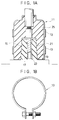
- FIGS 1A and 1B show structures of a conventional plug 11, a plug receiver 15 and ribbon-shape bands 13.
- the bands 13 are provided on the outer surface of the plug 11 to apply pressure to an insulating material incorporated therein.
- a pair of plug receivers 15 for electrical connection are provided on the electric device 12, and each receiver 15 is formed into a projection and comprises a contact terminal 17 and an insulating material 19 provided around the terminal 17.
- a cavity portion 21 of the plug 11 is fitted around these projections 15 so as to connect its contact terminal 23 to the contact terminals 17. Accordingly, it is possible to apply pressure to the insulating material 19 by compressing the plug 11 with the bands 13 from the outside. As a result, the dielectric strength of the material 19 can be increased.
- Fig.2 shows another conventional example. As shown in the same drawing, this case has an epoxy bushing 31 to which a protection tube 33 is secured with several screws. Moreover, the protection tube 33 has springs 35 for applying pressure to a semiconductive rubber layer 39 and an insulating rubber 41 through a metal plate 37.
- the present invention was made to solve the above-mentioned problem in the conventional technology, therefore, it is an object thereof to provide a high-voltage plug which can be easily handled and is excellent in the insulating ability.
- the present invention is characterized by a plug for performing electrical connection with being fitted around a plug receiver which includes power receiving means and is formed into a projection, comprising an electrically conductive part which is connected to a core wire of a power supply cable and has a connection part for connecting it to a contact terminal of the plug receiver, a semiconductive layer part which is provided around the conductive part so as to prevent from high voltages centering in small parts of the plug , an insulating layer part which is provided on the exterior of the semi-conductive layer part so as to protect an outer case from high voltages of the outer surface of the semi-conductive layer part, a fitting portion comprising a cavity which is fitted around the plug receiver so as to facilitate connection between the contact terminal of the plug receiver and the conductive part of the plug, pressurizing means for increasing a dielectric strength of the insulating layer part by pressure to be generated by slightly lessening the inner dimension of the fitting portion as compared with the outer dimension of the plug receiver, pressure control means for making the pressure to be uniform by changing the dimensions ,
- the above mentioned pressure control means is the most important element of the present invention. According to the above described construction of the present invention, it becomes possible to reduce the number of parts necessary for the plug system and facilitate attachment of the plug.
- Fig.4 shows schematic construction of a system utilizing the embodiment of the present invention.
- a high-voltage electric device not shown is contained in a box 51, and plug receivers 53 formed into a pair of projections are mounted on the box 51.
- the bottom end portion of an L-shape plug 55 is fitted to make electrical contact relation therewith.
- each plug 55 is connected to a power cable 57 comprising a 22 kv high-voltage crosslinking polyethylene cable at the right or left end portion thereof.
- these two plugs 55 have completely the same structure.
- Fig.5 shows a detailed cross section of the structure of the plug 55.
- the plug 55 is provided with an insulating layer 61 consisting of an L-shape insulating rubber material.
- a semi-conductive layer 63 consisting of an L-shape hard rubber material is embedded.
- the semiconductive layer 63 is provided coaxially to the upper central axis thereof with a copper conductive part 65 in which the left half portion is solid, but the right half portion is hollow.
- the conductive part 65 is electrically connected to a core wire 57a of the power cable 57 through a contact piece not shown in the same drawing. While, the left end portion of the conductive part 65 has a flat lower face and contains a female screw extending vertically in the same drawing at the central portion thereof. Moreover, the female screw is engaged with an upper male screw portion 67c of a contact terminal 67 which further includes a cylindrical lower portion 67a and a hexagonal-prism intermediate portion 67b.
- a truncated-cone-shape fitting portion 69 opening downwards is provided coaxially to the contact terminal 67 in the left end portion of the insulating layer 61.
- the upper portion 69a of the fitting portion 69 is formed with an annular portion 63a of the semiconductive layer 63, and the intermediate portion 69b is constructed with the insulating layer 61.
- the upper portion 69a and the intermediate portion 69b of the fitting portion 69 are connected to each other so as to form a continuous or the same side face of a truncated cone.
- a grounded outer cover 71 is provided on the outer surface of the insulating layer 61.
- the left bottom end portion of the cover 71 has a convex portion 71a with a substantially trapezoidal cross section on the inner circumference thereof as well as covers the left bottom end portion of the insulating layer 61.
- the power cable 57 is inserted into the plug 55 so as to connect the core wire 57a of the cable 57 with the conductive part 65 described above.
- an insulating tape 73 is wound around the right end portion of the outer cover 71.
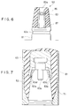
- Fig.6 shows a cross section of the plug receiver 53 to be fitted around in the above mentioned plug 55.
- the plug receiver 53 is mounted on an attachment base 81 of the box 51, and comprises a truncated-cone projection 83 consisting of an epoxy resin and extending upwards from the base 81.
- the projection 83 has a side face with the same inclination as that of the above-mentioned fitting portion 69 comprising the insulating layer 61 and semi-conductive layer 63, and the outer diameter of the former 83 is slightly larger (by about 2mm) than the inner diameter of the latter 69.
- a trapezoidal groove 83c with a diameter slightly larger (by about 2mm) than that of the above mentioned convex portion 71a is formed in the bottom end portion of the fitting portion 69. Therefore, the groove 83c serves as holding means for engaging the plug 55 with the plug receiver 53.
- a cylindrical hole 83a is formed in the projection 83 coaxially to the central axis thereof, and a cylindrical metal piece 87 is embedded in the inner wall of the hole 83a.
- a contact ring 85 electrically connecting to the metal piece 87 is provided at the intermediate portion of the hole 83.
- the bottom end of the metal piece 87 is connected to an input terminal of the above-described electric device.
- an insulating rubber material is used for producing the insulating layer 61
- a hard rubber material is used for the semi-conductive layer 63
- the conductive part 65 is made of copper
- the projection 83 of the plug receiver 53 consists of an epoxy resin.
- the pressure to be generated on the contact face between the plug 55 and the plug receiver 53 on engaging them with each other is adjusted at about several kg/cm2, for example, by setting the difference between the outer diameter of the projection 83 and the inner diameter of the fitting portion 69 at 1mm.
- the left lower portion of the insulating layer 61 interposed between the compression band and the projection 83 is compressed by both of the compression force of the band and the pressure generated by engagement of the fitting portion 69 and the projection 83. Therefore, the dielectric strength is elevated so that sufficient insulation ability of the insulating layer 61 can be guaranteed.
- the inner circumference of the annular portion 63a should be uniformly extended at the fitting part when the projection 83 is inserted in the fitting portion 69 of the plug 55, if both ends of the annular portion 63a were free.
- the base potion of the annular portion 63a is rigidly fixed with the body of the semiconductor layer 63, the base potion is little extended. Therefore, stress is generated only at the base portion , so that the portion 63a is deformed as shown in Fig.7 for the reason that will be explained below. That is, the annular portion 63a is bent more than the inclination angle of the side face of the truncated cone decided by the projection 83, and thereby a small gap 63d is formed between them.
- the structure of the semiconductive layer 63 is symmetrical about the central axis thereof, considering a sliced part cut off from the annular portion 63a by a very small length in a circular direction, then a deflection of the part is nearly equal to that of a cantilever applied with a force F1 caused by inserting the projection 83 into the annular portion 63a.
- the cantilever is bent to the deflection curve ⁇ 1 shown in Fig. 8A. And the deflection ⁇ 1 of the part causes a compression force F2 on the insulating layer 61 surrounding the annular portion 63a, which produce the reaction force F2 on the cantilever as shown in Fig. 8B. Then, the cantilever is also bent downwards to the deflection curve shown in the same figure. As a result, the cantilever is deformed into the the deflection curve ( ⁇ 1- ⁇ 2) as shown in Fig. 8C.
- the above-mentioned small gap 63d is generated between the annular portion 63a and the projection 83.
- a circular stress is also caused in the annular portion 63a by being extended in a circular direction, however it is not considered in the above discussion because of smallness of its influence to the deflection of the cantilever.
- the second embodiment of the present invention is so improved that the gap due to the insertion of the projection can be prevented, and preferred insulating ability can be maintained over a long term.
- the inclination gradient of the inner side wall of the annular portion 63a is set slightly larger as shown by the solid line in Fig.9 by enlarging the diameter of the top end portion thereof as compared with that in the first embodiment as shown by the dotted line in the same drawing.
- the force F1' applies to the cantilever instead of F1 when the projection inserts into annual portion 63a, which deflects the cantilever to the curve ⁇ 1' having an upward concave as shown in Fig.10C. And this deflection causes a force F2' as the same principle as described above, which bent the cantilever to the deflection curve ⁇ 2'. Therefore the cantilever, as a result, is bent in the deflection curve ( ⁇ 1'- ⁇ 2') shown in Fig. 10D. However, since ( ⁇ 1'- ⁇ 2') is nearly equal to zero at any points of the cantilever, the gap as above mentioned is not generated. As a result, discharge between the annular portion 63a and the projection 58 is not caused.
- the cable plug based on the construction of the second embodiment can prevent the gap generation between the annular portion 63a and the projection 83 as shown in Fig.7, it can maintain preferred insulating ability over a long period of time.
- the same effect can be obtained by modifying the outer diameter of the distal end portion of the projection 83.
- the inclination of the side wall of the projection 83 may be decreased by reducing the diameter of the distal end portion by about 1.6 mm.
- annular portion 63a may be changed into a curve.
- the fitting portion may be also applied to T-shape, Y-shape or cross-type cable plugs.
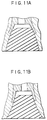
- the shape of the fitting portion is not limited to the truncated cone type, but the portion may be formed in a shape with a narrow skirt portion as shown in Fig.11(a) or in a shape with a wide skirt portion as shown in Fig.11(b).
Landscapes
- Connector Housings Or Holding Contact Members (AREA)
Abstract
Description
- The present invention relates to a cable plug for high voltage usage, or a high-voltage plug. More particularly, this invention relates to a plug for connecting a power cable to an electric device which is operated at voltage of 1 kv to several 10 kv.
- In case of connecting a power cable to an electric device which is operated at about 1 kv to some 10 kv, it is necessary to insulate the cable with special means. Namely, to prevent a high-voltage current flowing in the conductive wire of the cable from leaking, special structures and materials for insulating the plug have been proposed or used so far.
- As the materials for insulating such a high-voltage plug, insulating rubbers and other organic materials such as polyethylene have been used. However, a dielectric strength of these materials is apt to change with applied pressure thereto as shown in Fig.3. Namely, the dielectric strength increases as the pressure becomes large until the pressure reaches a certain value.
- Accordingly, conventional high-voltage plugs are provided with means for increasing the dielectric strength of such insulating materials by applying suitable pressure thereto. Two typical examples of such conventional high-voltage plugs are explained here.
- Figures 1A and 1B show structures of a
conventional plug 11, aplug receiver 15 and ribbon-shape bands 13. Thebands 13 are provided on the outer surface of theplug 11 to apply pressure to an insulating material incorporated therein. In more detail, a pair ofplug receivers 15 for electrical connection are provided on the electric device 12, and eachreceiver 15 is formed into a projection and comprises acontact terminal 17 and aninsulating material 19 provided around theterminal 17. Moreover, acavity portion 21 of theplug 11 is fitted around theseprojections 15 so as to connect itscontact terminal 23 to thecontact terminals 17. Accordingly, it is possible to apply pressure to the insulatingmaterial 19 by compressing theplug 11 with thebands 13 from the outside. As a result, the dielectric strength of thematerial 19 can be increased. - Fig.2 shows another conventional example. As shown in the same drawing, this case has an
epoxy bushing 31 to which aprotection tube 33 is secured with several screws. Moreover, theprotection tube 33 hassprings 35 for applying pressure to asemiconductive rubber layer 39 and aninsulating rubber 41 through ametal plate 37. - As explained above, the structure of these conventional plugs is so complicated that handling these plugs is very troublesome, moreover, it is very difficult to uniformly apply pressure to the insulating materials.
- The present invention was made to solve the above-mentioned problem in the conventional technology, therefore, it is an object thereof to provide a high-voltage plug which can be easily handled and is excellent in the insulating ability.
- To achieve this object, the present invention is characterized by a plug for performing electrical connection with being fitted around a plug receiver which includes power receiving means and is formed into a projection, comprising an electrically conductive part which is connected to a core wire of a power supply cable and has a connection part for connecting it to a contact terminal of the plug receiver, a semiconductive layer part which is provided around the conductive part so as to prevent from high voltages centering in small parts of the plug , an insulating layer part which is provided on the exterior of the semi-conductive layer part so as to protect an outer case from high voltages of the outer surface of the semi-conductive layer part,a fitting portion comprising a cavity which is fitted around the plug receiver so as to facilitate connection between the contact terminal of the plug receiver and the conductive part of the plug, pressurizing means for increasing a dielectric strength of the insulating layer part by pressure to be generated by slightly lessening the inner dimension of the fitting portion as compared with the outer dimension of the plug receiver, pressure control means for making the pressure to be uniform by changing the dimensions , and holding means for engaging the the plug to the plug receiver.
- In particular, the above mentioned pressure control means is the most important element of the present invention. According to the above described construction of the present invention, it becomes possible to reduce the number of parts necessary for the plug system and facilitate attachment of the plug.
- These and other objects, features and advantages of the present invention will be more apparent from the following description of a preferred embodiment, taken in conjuction with the accompanying drawings.
-
- Fig.1 shows an example of conventional high-voltage plugs;
- Fig.2 shows another example of conventional high-voltage plugs;
- Fig.3 shows relation between pressures to be applied to a insulating material and dielectric strengths of the insulating material;
- Fig.4 shows a schematic construction of a system utilizing a first embodiment of the present invention;
- Fig.5 shows a cross section of a plug used in the first embodiment;
- Fig.6 shows a cross section of a plug receiver to be fitted around in the plug shown in Fig.5 so as to supply the system with high voltage;
- Fig.7 is a diagram for explaining a problem to be more improved in the first embodiment;
- Figs.8A to 8C are diagrams for explaining phenomena by which the problem explained by Fig.7 is caused;
- Fig.9 shows points improved in a second embodiment of the present invention;
- Figs.10A to 10D are diagrams for explaining the effect of the improvement in the second embodiment; and
- Figs.11A and 11B respectively show another embodiments of the present invention.
- Hereinafter, a first embodiment of the present invention and a second embodiment in which a problem of the first embodiment is improved will be respectively explained.
- Fig.4 shows schematic construction of a system utilizing the embodiment of the present invention. In the same drawing, a high-voltage electric device not shown is contained in a
box 51, andplug receivers 53 formed into a pair of projections are mounted on thebox 51. Around each of theseplug receivers 53, the bottom end portion of an L-shape plug 55 is fitted to make electrical contact relation therewith. Moreover, eachplug 55 is connected to apower cable 57 comprising a 22 kv high-voltage crosslinking polyethylene cable at the right or left end portion thereof. Incidentally, these twoplugs 55 have completely the same structure. - Fig.5 shows a detailed cross section of the structure of the
plug 55. As shown in the same drawing, theplug 55 is provided with aninsulating layer 61 consisting of an L-shape insulating rubber material. At the central portion of the corner portion in theinsulating layer 61, asemi-conductive layer 63 consisting of an L-shape hard rubber material is embedded. Moreover, thesemiconductive layer 63 is provided coaxially to the upper central axis thereof with a copperconductive part 65 in which the left half portion is solid, but the right half portion is hollow. - At the right end portion, the
conductive part 65 is electrically connected to acore wire 57a of thepower cable 57 through a contact piece not shown in the same drawing. While, the left end portion of theconductive part 65 has a flat lower face and contains a female screw extending vertically in the same drawing at the central portion thereof. Moreover, the female screw is engaged with an upper male screw portion 67c of a contact terminal 67 which further includes a cylindricallower portion 67a and a hexagonal-prismintermediate portion 67b. - Moreover, a truncated-cone-
shape fitting portion 69 opening downwards is provided coaxially to the contact terminal 67 in the left end portion of theinsulating layer 61. Theupper portion 69a of thefitting portion 69 is formed with anannular portion 63a of thesemiconductive layer 63, and theintermediate portion 69b is constructed with theinsulating layer 61. Besides, theupper portion 69a and theintermediate portion 69b of thefitting portion 69 are connected to each other so as to form a continuous or the same side face of a truncated cone. - A grounded
outer cover 71 is provided on the outer surface of theinsulating layer 61. The left bottom end portion of thecover 71 has aconvex portion 71a with a substantially trapezoidal cross section on the inner circumference thereof as well as covers the left bottom end portion of theinsulating layer 61. Through an opening of the right end portion of theouter cover 71 or of the right end portion of theinsulating layer 61, thepower cable 57 is inserted into theplug 55 so as to connect thecore wire 57a of thecable 57 with theconductive part 65 described above. Moreover, aninsulating tape 73 is wound around the right end portion of theouter cover 71. - Fig.6 shows a cross section of the
plug receiver 53 to be fitted around in the above mentionedplug 55. Theplug receiver 53 is mounted on anattachment base 81 of thebox 51, and comprises a truncated-cone projection 83 consisting of an epoxy resin and extending upwards from thebase 81. Theprojection 83 has a side face with the same inclination as that of the above-mentionedfitting portion 69 comprising theinsulating layer 61 andsemi-conductive layer 63, and the outer diameter of the former 83 is slightly larger (by about 2mm) than the inner diameter of the latter 69. - Namely, due to the slight difference between these two outer diameters, pressure is applied to the insulating
layer 61 when theplug 51 is fitted around theplug receiver 53. Incidentally, atrapezoidal groove 83c with a diameter slightly larger (by about 2mm) than that of the above mentionedconvex portion 71a is formed in the bottom end portion of thefitting portion 69. Therefore, thegroove 83c serves as holding means for engaging theplug 55 with theplug receiver 53. - Moreover, a
cylindrical hole 83a is formed in theprojection 83 coaxially to the central axis thereof, and acylindrical metal piece 87 is embedded in the inner wall of thehole 83a. At the intermediate portion of thehole 83, acontact ring 85 electrically connecting to themetal piece 87 is provided. Incidentally, the bottom end of themetal piece 87 is connected to an input terminal of the above-described electric device. - In this embodiment, an insulating rubber material is used for producing the insulating
layer 61, a hard rubber material is used for thesemi-conductive layer 63 and theconductive part 65 is made of copper, moreover, theprojection 83 of theplug receiver 53 consists of an epoxy resin. - Moreover, the pressure to be generated on the contact face between the
plug 55 and theplug receiver 53 on engaging them with each other is adjusted at about several kg/cm2, for example, by setting the difference between the outer diameter of theprojection 83 and the inner diameter of thefitting portion 69 at 1mm. - In such a cable plug constructed as mentioned above, when the
fitting portion 69 of theplug 55 is fitted around the truncated-cone projection 83 on theattachment base 81, the above mentionedcontact ring 85 is electrically connected to theconductive part 65 through the contact terminal 67 incorporated in theplug 55. Moreover, when theconvex portion 71a is completely fitted in thegroove 83c, the insertion position of theprojection 83 to theplug 55 is determined. Incidentally, theplug 55 is compressed by a compression band which is not shown in the drawings, but is wound around the outer circumference of the left bottom end portion of theplug 55. - Accordingly, the left lower portion of the insulating
layer 61 interposed between the compression band and theprojection 83 is compressed by both of the compression force of the band and the pressure generated by engagement of thefitting portion 69 and theprojection 83. Therefore, the dielectric strength is elevated so that sufficient insulation ability of the insulatinglayer 61 can be guaranteed. - Then, in this case, the inner circumference of the
annular portion 63a should be uniformly extended at the fitting part when theprojection 83 is inserted in thefitting portion 69 of theplug 55, if both ends of theannular portion 63a were free. However, as the base potion of theannular portion 63a is rigidly fixed with the body of thesemiconductor layer 63, the base potion is little extended. Therefore, stress is generated only at the base portion , so that theportion 63a is deformed as shown in Fig.7 for the reason that will be explained below. That is, theannular portion 63a is bent more than the inclination angle of the side face of the truncated cone decided by theprojection 83, and thereby asmall gap 63d is formed between them. - As a result, high voltage is generated between the
small gap 63d, so that slight electric discharge is caused. Accordingly, the insulating ability of an epoxy resin portion included in theprojection 53 corresponding to thesmall gap 63d is deteriorated during long-term operation, and the dielectric strength thereof is also lowered. - Hereinafter, the reason of generation of the
small gap 63d will be explained. - Since the structure of the
semiconductive layer 63 is symmetrical about the central axis thereof, considering a sliced part cut off from theannular portion 63a by a very small length in a circular direction, then a deflection of the part is nearly equal to that of a cantilever applied with a force F1 caused by inserting theprojection 83 into theannular portion 63a. - According to a principle of strength of materials, the cantilever is bent to the deflection curve δ1 shown in Fig. 8A. And the deflection δ1 of the part causes a compression force F2 on the insulating
layer 61 surrounding theannular portion 63a, which produce the reaction force F2 on the cantilever as shown in Fig. 8B. Then, the cantilever is also bent downwards to the deflection curve shown in the same figure. As a result, the cantilever is deformed into the the deflection curve (δ1-δ2) as shown in Fig. 8C. - Accordingly, the above-mentioned
small gap 63d is generated between theannular portion 63a and theprojection 83. Practically, a circular stress is also caused in theannular portion 63a by being extended in a circular direction, however it is not considered in the above discussion because of smallness of its influence to the deflection of the cantilever. - To solve this problem in the above described embodiment, the second embodiment of the present invention is so improved that the gap due to the insertion of the projection can be prevented, and preferred insulating ability can be maintained over a long term.
- Namely, in the second embodiment, the inclination gradient of the inner side wall of the
annular portion 63a is set slightly larger as shown by the solid line in Fig.9 by enlarging the diameter of the top end portion thereof as compared with that in the first embodiment as shown by the dotted line in the same drawing. - In more detail, now considered is a case where the inclination gradient of the inner side wall of the
annular portion 63a is changed as shown in Fig.10A. - In this modified case, the force F1' applies to the cantilever instead of F1 when the projection inserts into
annual portion 63a, which deflects the cantilever to the curve δ1' having an upward concave as shown in Fig.10C. And this deflection causes a force F2' as the same principle as described above, which bent the cantilever to the deflection curve δ2'. Therefore the cantilever, as a result, is bent in the deflection curve ( δ1'- δ2') shown in Fig. 10D. However, since (δ1'- δ2') is nearly equal to zero at any points of the cantilever, the gap as above mentioned is not generated. As a result, discharge between theannular portion 63a and the projection 58 is not caused. - Accordingly, by modifying the structure of the
annular portion 63a as designed in the second embodiment, the problem to be caused by the above-mentioned small gap can be almost avoided. - Therefore, since the cable plug based on the construction of the second embodiment can prevent the gap generation between the
annular portion 63a and theprojection 83 as shown in Fig.7, it can maintain preferred insulating ability over a long period of time. - Incidentally, though the inner diameter of the
annular portion 63a of thesemi-conductive layer 63 is changed in the second embodiment, the same effect can be obtained by modifying the outer diameter of the distal end portion of theprojection 83. Namely, the inclination of the side wall of theprojection 83 may be decreased by reducing the diameter of the distal end portion by about 1.6 mm. - Moreover, though the side wall of
annular portion 63a is lineally modified, it may be changed into a curve. - Besides, though the L-shape cable plug is mentioned in the first and second embodiments, the fitting portion may be also applied to T-shape, Y-shape or cross-type cable plugs.
- In addition, the shape of the fitting portion is not limited to the truncated cone type, but the portion may be formed in a shape with a narrow skirt portion as shown in Fig.11(a) or in a shape with a wide skirt portion as shown in Fig.11(b).
- Various modifications will become possible for those skilled in the art after receiving the teachings of the present disclosure without departing from the scope thereof.
Claims (8)
- High-voltage plug (55) for performing electrical connection with being fitted around a plug receiver (53) which includes power receiving means (87) and is formed into a projection (83), comprising:(1) an electrically conductive part (65, 67) which is connected to a core wire (57a) of a power-supply cable (57) and has a connection part (67a) for connecting to a contact terminal (85) of the plug receiver (53);(2) a semi-conductive layer part (63) which is provided around the conductive part (65, 67) so as to prevent from high voltages centering in small parts of the plug;(3) an insulating layer part (61) which is provided on the exterior of the semi-conductive layer part (63) so as to insulate an outer case (71) from high voltage portions in the plug;(4) a fitting portion (69) comprising a cavity whose opening is fitted around the plug receiver (53) so as to facilitate connection between the contact terminal (85) of the plug receiver and the conductive part (67a) of the plug;(5) pressurizing means for increasing a dielectric strength of the insulating layer part (61) by pressure to be generated by slightly lessening the inner dimension of the fitting portion as compared with the outer dimension of the plug receiver (83);(6) pressure control means for making the pressure to be uniform by changing the dimensions; and(7) holding means (71a) for engaging the plug (55) with the plug receiver (53).
- Plug according to claim 1, wherein:(1) the fitting portion (69) is formed into a truncated cone shape where the diameter of the opening is larger than that of the top end portion, and the height is slightly larger than that of the projection (83) of the plug receiver (53) to produce a space when they are fitted;(2) the fitting portion (69) is having an opening front portion consisting of the insulating layer part (61) and an annular rear portion (63a) consisting of the semiconductive layer part (63) of which inside wall completely covers the space; further(3) the inclination gradient of the side wall in the opening portion (69b) corresponding to the annular portion (63a) is set slightly larger than that corresponding to the insulating layer part so that the difference between the inner diameter of the annular portion and the outer diameter of the projection of the plug receiver is gradually reduced toward the top end portion, whereby the pressure to be applied over the contact face can be suitable controlled.
- Plug according to claim 2, wherein:
the difference between the inner diameter of the annular portion (63a) and the outer diameter of the projection (83) is linearly reduced toward to the top so as to control the pressure to be applied over the contact face. - Plug according to claim 3, wherein:
the difference is made zero at the top end portion of the annular portion (63a). - Plug according to any of claims 2 to 4, wherein:
the skirt portion of the truncated cone shape in the fitting portion and the projection of the plug receiver is slightly narrowed. - Plug according to any of claims 2 to 4, wherein:
the skirt portion of the truncated cone shape in the fitting portion and the projection of the plug receiver is slightly spread. - Plug according to any of claims 1 to 6, wherein:
the plug is formed into a L shape, and is provided with the fitting portion at one end thereof and an opening for connection to a power supply cable at the other end thereof. - Plug according to any of claims 1 to 6, wherein:
the plug is formed into a T shape.
Applications Claiming Priority (2)
| Application Number | Priority Date | Filing Date | Title |
|---|---|---|---|
| JP2312721A JP2866473B2 (en) | 1990-11-20 | 1990-11-20 | Cable plug |
| JP312721/90 | 1990-11-20 |
Publications (2)
| Publication Number | Publication Date |
|---|---|
| EP0487025A1 true EP0487025A1 (en) | 1992-05-27 |
| EP0487025B1 EP0487025B1 (en) | 1995-04-19 |
Family
ID=18032622
Family Applications (1)
| Application Number | Title | Priority Date | Filing Date |
|---|---|---|---|
| EP19910119716 Expired - Lifetime EP0487025B1 (en) | 1990-11-20 | 1991-11-19 | Power electrical cable plug |
Country Status (3)
| Country | Link |
|---|---|
| EP (1) | EP0487025B1 (en) |
| JP (1) | JP2866473B2 (en) |
| DE (1) | DE69109060T2 (en) |
Cited By (6)
| Publication number | Priority date | Publication date | Assignee | Title |
|---|---|---|---|---|
| WO1994002977A1 (en) * | 1992-07-25 | 1994-02-03 | Karl Pfisterer Elektrotechnische Spezialartikel Gmbh & Co. Kg | Plug |
| WO1994002976A1 (en) * | 1992-07-25 | 1994-02-03 | Karl Pfisterer Elektrotechnische Spezialartikel Gmbh & Co. Kg | Angled plug |
| WO1996019024A1 (en) * | 1994-12-12 | 1996-06-20 | N.V. Raychem S.A. | Sealing device |
| EP0716488A3 (en) * | 1994-12-08 | 1997-02-19 | Ritz Messwandler Kg | High voltage connector |
| EP2490302A1 (en) * | 2011-02-15 | 2012-08-22 | GE Sensing & Inspection Technologies GmbH | High voltage plug connection part for high voltage cable and method for producing same |
| WO2014084052A1 (en) * | 2012-11-28 | 2014-06-05 | 株式会社オートネットワーク技術研究所 | L-shaped terminal metal fitting and l-shaped connector employing same |
Families Citing this family (4)
| Publication number | Priority date | Publication date | Assignee | Title |
|---|---|---|---|---|
| KR20130059564A (en) * | 2011-11-29 | 2013-06-07 | 엘지이노텍 주식회사 | Terminal cable assembly having water proof structure |
| JP6438675B2 (en) * | 2014-04-28 | 2018-12-19 | 矢崎総業株式会社 | Connector waterproof structure |
| CN111682500B (en) * | 2020-06-28 | 2022-05-06 | 中科英华长春高技术有限公司 | 35kV separable connector for offshore wind power |
| EP4167391A1 (en) * | 2021-10-13 | 2023-04-19 | ASML Netherlands B.V. | Electrical connector for high power in a vacuum environment and method |
Citations (4)
| Publication number | Priority date | Publication date | Assignee | Title |
|---|---|---|---|---|
| FR1455728A (en) * | 1964-12-14 | 1966-10-14 | Amp Inc | High voltage electrical connection device |
| DE2441091A1 (en) * | 1974-08-28 | 1976-03-11 | Felten & Guilleaume Kabelwerk | Insulating of cable end or joint - using outer elastic winding under tension |
| EP0148394A2 (en) * | 1983-11-30 | 1985-07-17 | Kabushiki Kaisha Toshiba | Enclosed switchgears |
| EP0389677A2 (en) * | 1989-03-29 | 1990-10-03 | AMERACE CORPORATION (a Delaware corporation) | 600-AMP hot stick-operable pin-and-socket assembled connector system |
-
1990
- 1990-11-20 JP JP2312721A patent/JP2866473B2/en not_active Expired - Lifetime
-
1991
- 1991-11-19 DE DE1991609060 patent/DE69109060T2/en not_active Expired - Fee Related
- 1991-11-19 EP EP19910119716 patent/EP0487025B1/en not_active Expired - Lifetime
Patent Citations (4)
| Publication number | Priority date | Publication date | Assignee | Title |
|---|---|---|---|---|
| FR1455728A (en) * | 1964-12-14 | 1966-10-14 | Amp Inc | High voltage electrical connection device |
| DE2441091A1 (en) * | 1974-08-28 | 1976-03-11 | Felten & Guilleaume Kabelwerk | Insulating of cable end or joint - using outer elastic winding under tension |
| EP0148394A2 (en) * | 1983-11-30 | 1985-07-17 | Kabushiki Kaisha Toshiba | Enclosed switchgears |
| EP0389677A2 (en) * | 1989-03-29 | 1990-10-03 | AMERACE CORPORATION (a Delaware corporation) | 600-AMP hot stick-operable pin-and-socket assembled connector system |
Cited By (7)
| Publication number | Priority date | Publication date | Assignee | Title |
|---|---|---|---|---|
| WO1994002977A1 (en) * | 1992-07-25 | 1994-02-03 | Karl Pfisterer Elektrotechnische Spezialartikel Gmbh & Co. Kg | Plug |
| WO1994002976A1 (en) * | 1992-07-25 | 1994-02-03 | Karl Pfisterer Elektrotechnische Spezialartikel Gmbh & Co. Kg | Angled plug |
| EP0716488A3 (en) * | 1994-12-08 | 1997-02-19 | Ritz Messwandler Kg | High voltage connector |
| WO1996019024A1 (en) * | 1994-12-12 | 1996-06-20 | N.V. Raychem S.A. | Sealing device |
| EP2490302A1 (en) * | 2011-02-15 | 2012-08-22 | GE Sensing & Inspection Technologies GmbH | High voltage plug connection part for high voltage cable and method for producing same |
| US8657618B2 (en) | 2011-02-15 | 2014-02-25 | Ge Sensing And Inspection Technologies Gmbh | High-voltage connector component for a high-voltage cable, high-voltage connector, and method of manufacturing a high-voltage connector component |
| WO2014084052A1 (en) * | 2012-11-28 | 2014-06-05 | 株式会社オートネットワーク技術研究所 | L-shaped terminal metal fitting and l-shaped connector employing same |
Also Published As
| Publication number | Publication date |
|---|---|
| DE69109060T2 (en) | 1996-01-04 |
| JPH04184875A (en) | 1992-07-01 |
| EP0487025B1 (en) | 1995-04-19 |
| JP2866473B2 (en) | 1999-03-08 |
| DE69109060D1 (en) | 1995-05-24 |
Similar Documents
| Publication | Publication Date | Title |
|---|---|---|
| US5120260A (en) | Connector for semi-rigid coaxial cable | |
| JP5231583B2 (en) | Air termination box | |
| US3328744A (en) | Corona resistant lead and terminal assembly | |
| US3770878A (en) | Hermetically sealed electrical terminal | |
| EP0487025B1 (en) | Power electrical cable plug | |
| US3275737A (en) | Coaxial cable terminating means | |
| US4053702A (en) | Dielectric stress relief at a high voltage cable termination | |
| US6075209A (en) | Insulated cap for loadbreak bushing | |
| US4266841A (en) | High voltage cable terminal | |
| US3277423A (en) | High-voltage electrical connector | |
| US2449570A (en) | Electrical connector | |
| US4404423A (en) | Three-phase gas insulated bus | |
| US4780577A (en) | Electrical bushing of a gas insulated electrical apparatus | |
| US4037187A (en) | Metal clad insulating circuit breaker | |
| US2337800A (en) | Plug-in terminal for electric cables | |
| JP2002165351A (en) | Cable terminal part and cable terminal connect part using thereof | |
| JPH0754775B2 (en) | Device for connecting high voltage lead-out cables to high voltage transformers without high voltage lead-out cables | |
| JP5926664B2 (en) | Cable connection | |
| US1703409A (en) | High-voltage terminal | |
| US2868866A (en) | Lead-in bushings | |
| US6535097B1 (en) | Transformer system provided with a decoupling system | |
| JP2529335Y2 (en) | L-type connector plug | |
| JP2002135959A (en) | Connection structure cable termination electrical apparatus | |
| JP3352529B2 (en) | Cable end structure for junction box and its outer plug | |
| JPH05166440A (en) | Vacuum switch |
Legal Events
| Date | Code | Title | Description |
|---|---|---|---|
| PUAI | Public reference made under article 153(3) epc to a published international application that has entered the european phase |
Free format text: ORIGINAL CODE: 0009012 |
|
| 17P | Request for examination filed |
Effective date: 19911119 |
|
| AK | Designated contracting states |
Kind code of ref document: A1 Designated state(s): DE FR NL |
|
| 17Q | First examination report despatched |
Effective date: 19940125 |
|
| GRAA | (expected) grant |
Free format text: ORIGINAL CODE: 0009210 |
|
| AK | Designated contracting states |
Kind code of ref document: B1 Designated state(s): DE FR NL |
|
| REF | Corresponds to: |
Ref document number: 69109060 Country of ref document: DE Date of ref document: 19950524 |
|
| ET | Fr: translation filed | ||
| PLBE | No opposition filed within time limit |
Free format text: ORIGINAL CODE: 0009261 |
|
| STAA | Information on the status of an ep patent application or granted ep patent |
Free format text: STATUS: NO OPPOSITION FILED WITHIN TIME LIMIT |
|
| 26N | No opposition filed | ||
| PGFP | Annual fee paid to national office [announced via postgrant information from national office to epo] |
Ref country code: FR Payment date: 19961007 Year of fee payment: 6 |
|
| PGFP | Annual fee paid to national office [announced via postgrant information from national office to epo] |
Ref country code: DE Payment date: 19961128 Year of fee payment: 6 |
|
| PGFP | Annual fee paid to national office [announced via postgrant information from national office to epo] |
Ref country code: NL Payment date: 19961129 Year of fee payment: 6 |
|
| PG25 | Lapsed in a contracting state [announced via postgrant information from national office to epo] |
Ref country code: FR Free format text: THE PATENT HAS BEEN ANNULLED BY A DECISION OF A NATIONAL AUTHORITY Effective date: 19971130 |
|
| PG25 | Lapsed in a contracting state [announced via postgrant information from national office to epo] |
Ref country code: NL Free format text: LAPSE BECAUSE OF NON-PAYMENT OF DUE FEES Effective date: 19980601 |
|
| PG25 | Lapsed in a contracting state [announced via postgrant information from national office to epo] |
Ref country code: DE Free format text: LAPSE BECAUSE OF NON-PAYMENT OF DUE FEES Effective date: 19980801 |
|
| NLV4 | Nl: lapsed or anulled due to non-payment of the annual fee |
Effective date: 19980601 |
|
| REG | Reference to a national code |
Ref country code: FR Ref legal event code: ST |