EP0491741B1 - Wärmeübertragungsgerät - Google Patents
Wärmeübertragungsgerät Download PDFInfo
- Publication number
- EP0491741B1 EP0491741B1 EP90912986A EP90912986A EP0491741B1 EP 0491741 B1 EP0491741 B1 EP 0491741B1 EP 90912986 A EP90912986 A EP 90912986A EP 90912986 A EP90912986 A EP 90912986A EP 0491741 B1 EP0491741 B1 EP 0491741B1
- Authority
- EP
- European Patent Office
- Prior art keywords
- unit
- heat exchange
- flow pathway
- exchange apparatus
- impeller
- Prior art date
- Legal status (The legal status is an assumption and is not a legal conclusion. Google has not performed a legal analysis and makes no representation as to the accuracy of the status listed.)
- Expired - Lifetime
Links
Images


Classifications
-
- F—MECHANICAL ENGINEERING; LIGHTING; HEATING; WEAPONS; BLASTING
- F24—HEATING; RANGES; VENTILATING
- F24F—AIR-CONDITIONING; AIR-HUMIDIFICATION; VENTILATION; USE OF AIR CURRENTS FOR SCREENING
- F24F12/00—Use of energy recovery systems in air conditioning, ventilation or screening
- F24F12/001—Use of energy recovery systems in air conditioning, ventilation or screening with heat-exchange between supplied and exhausted air
-
- B—PERFORMING OPERATIONS; TRANSPORTING
- B60—VEHICLES IN GENERAL
- B60H—ARRANGEMENTS OF HEATING, COOLING, VENTILATING OR OTHER AIR-TREATING DEVICES SPECIALLY ADAPTED FOR PASSENGER OR GOODS SPACES OF VEHICLES
- B60H1/00—Heating, cooling or ventilating devices
- B60H1/02—Heating, cooling or ventilating devices the heat being derived from the propulsion plant
- B60H1/03—Heating, cooling or ventilating devices the heat being derived from the propulsion plant and from a source other than the propulsion plant
- B60H1/039—Heating, cooling or ventilating devices the heat being derived from the propulsion plant and from a source other than the propulsion plant from air leaving the interior of the vehicle, i.e. heat recovery
-
- F—MECHANICAL ENGINEERING; LIGHTING; HEATING; WEAPONS; BLASTING
- F04—POSITIVE - DISPLACEMENT MACHINES FOR LIQUIDS; PUMPS FOR LIQUIDS OR ELASTIC FLUIDS
- F04D—NON-POSITIVE-DISPLACEMENT PUMPS
- F04D29/00—Details, component parts, or accessories
- F04D29/58—Cooling; Heating; Diminishing heat transfer
- F04D29/582—Cooling; Heating; Diminishing heat transfer specially adapted for elastic fluid pumps
- F04D29/5826—Cooling at least part of the working fluid in a heat exchanger
-
- Y—GENERAL TAGGING OF NEW TECHNOLOGICAL DEVELOPMENTS; GENERAL TAGGING OF CROSS-SECTIONAL TECHNOLOGIES SPANNING OVER SEVERAL SECTIONS OF THE IPC; TECHNICAL SUBJECTS COVERED BY FORMER USPC CROSS-REFERENCE ART COLLECTIONS [XRACs] AND DIGESTS
- Y02—TECHNOLOGIES OR APPLICATIONS FOR MITIGATION OR ADAPTATION AGAINST CLIMATE CHANGE
- Y02B—CLIMATE CHANGE MITIGATION TECHNOLOGIES RELATED TO BUILDINGS, e.g. HOUSING, HOUSE APPLIANCES OR RELATED END-USER APPLICATIONS
- Y02B30/00—Energy efficient heating, ventilation or air conditioning [HVAC]
- Y02B30/56—Heat recovery units
-
- Y—GENERAL TAGGING OF NEW TECHNOLOGICAL DEVELOPMENTS; GENERAL TAGGING OF CROSS-SECTIONAL TECHNOLOGIES SPANNING OVER SEVERAL SECTIONS OF THE IPC; TECHNICAL SUBJECTS COVERED BY FORMER USPC CROSS-REFERENCE ART COLLECTIONS [XRACs] AND DIGESTS
- Y10—TECHNICAL SUBJECTS COVERED BY FORMER USPC
- Y10S—TECHNICAL SUBJECTS COVERED BY FORMER USPC CROSS-REFERENCE ART COLLECTIONS [XRACs] AND DIGESTS
- Y10S165/00—Heat exchange
- Y10S165/909—Regeneration
Definitions
- This invention relates to heat exchange apparatus for exchanging heat between fluids.
- the heat exchange apparatus may, for example, find application as part of an air conditioning unit or a heat pump.
- the invention relates in particular to a compact heat exchange apparatus suitable for application as a room or car air conditioner/heater.
- heat exchange apparatus comprising a first heat exchange unit and a second heat exchange unit, each heat exchange unit having a fluid impeller and a heat conductive wall about the impeller, wherein each said unit has a first flow pathway, about the impeller, internally of the wall, and a second flow pathway, externally of the wall; the first and second units being so connected that the first flow pathway of the first unit communicates, via the impeller of the first unit, with the second flow pathway of the second unit; and the first flow pathway of the second unit communicates, via the impeller of the second unit, with the second flow pathway of the first unit.
- each heat exchange unit is of spiral form thereby enclosing a volute within which the impeller is located.
- the first pathway of each unit continues beyond the volute in a spiral conformation.
- each heat exchange unit may thus comprise two flow pathways of spiral conformation, interleaved with each other, and isolated from each other by means of two heat conductive walls.
- Fluid flow in the second pathway of each heat exchange unit is preferably in the spiral direction, though could, in certain embodiments, be in the axial direction.
- the second flow pathway of each heat exchange unit may communicate with a transfer port located substantially at the innermost region of the pathway, the transfer port permitting fluid to enter or leave the pathway by flow in a direction which is transverse to the flow, in a spiral direction, within the pathway.
- the fluid is moved in one sense along one pathway and in the opposite sense along an adjacent pathway, in each unit.
- Each unit may have two fluid pathways as described, or may have further such fluid pathways, each fluid pathway being separated from each adjacent pathway by a heat conductive wall.
- the heat conductive wall(s) is/are constituted by flexible strip(s), preferably of a metallic material.
- the metallic material is thin, suitably about 0.1-0.5 mm, so that its heat capacity is low, whereby the thermal lag of the heat exchange unit is low.
- each said heat exchange unit comprises a fluid impeller, for example a centrifugal fan, located in its eye, suitably a volute.
- the fluid impellers are preferably driven by a common motor, suitably located between the impellers. In this way, a heat exchange unit in accordance with the invention may be compact, yet provide efficient heat transfer.
- the first and second units are located together substantially in face-to-face contact, the first and second units defining respective hollows, which oppose each other but with a lateral offset from each other, wherein the units have partitioning between them, the arrangement being such that the communication between the second flow pathway of the first unit and the first flow pathway of the second unit is via a transfer port in the partitioning at the position at which the second hollow extends laterally beyond the first hollow, and via the impeller of the second unit; and the communication between the second flow pathway of the second unit and the first flow pathway of the first unit is via a transfer port in the partitioning at the position at which the first hollow extends laterally beyond the second hollow, and via the impeller of the first unit.
- the second heat unit is arranged upside down relative to the first unit and the said hollows are axial continuations of respective volutes of the units, wherein each transfer port is aligned with a region of the volute of the other unit.
- Heat exchange apparatus in accordance with the present invention is compact and efficient, and is particularly well suited for the exchange of heat between gaseous media, for example, air/air. It may be especially useful as an air conditioner/heater for use in a car or building, extracting air from the interior and bringing in air from the exterior; in winter extracting heat from the outgoing interior air and transferring it to the incoming exterior air, and in summer extracting heat from the incoming exterior air and transferring it to the outgoing interior air. In so doing, moreover, condensation problems are reduced, the interior air generally being moister then the exterior air.
- Efficient car or household heat exchange apparatus comprising two heat exchange units, as previously described, may be a cube of size about 30 cm x 30 cm x 30 cm.
- heat exchange apparatus in accordance with the present invention is through-wall heat exchange apparatus, exchanging heat between a car or room of a house, and the outside.
- an auxiliary heating device conveniently an electric heating element
- modules securable to the apparatus for example a heater module as described above, a cooling module, a humidifying or dehumidifying module, an electrostatic filter module or a perfuming/room freshening module.
- modules may conveniently be securable over the "interior outlet" of the unit, for example replacing the standard fascia of the unit.
- Heat exchange apparatus for use in a household context can be a main apparatus serving a number of rooms via ducting.
- the modules described above may be incorporated in the ducting or at the "interior outlets" of such a system.
- Heater or cooling modules when provided, are preferably located at the "interior outlets”.
- Heat exchange apparatus in accordance with the invention may find application in other areas, for example, as a high temperature heat exchanger, or as a heat pump.
- a heat exchange apparatus in accordance with the invention has a heat conductive wall which is a flexible strip of heat conductive material, and the apparatus comprises spaced-apart, parallel, support plates formed with opposed aligned curved grooves, the apparatus having been made by feeding the flexible strip of heat conductive material lengthwise into the opposed aligned curved grooves respectively provided in the spaced-apart support plates.
- the heat exchange apparatus comprises a first heat exchange unit 2, and a second heat exchange unit 4, units 2 and 4 being arranged side by side with a space between them.
- the first heat exchange unit 2 comprises two interleaved spiral flow pathways 6, 8.
- Each spiral pathway is bounded by parallel side walls 10, 12 (Fig. 3), suitably of a plastics material, and by a pair of flexible aluminium strips 14/15 and 15/16, set between the side walls 10, 12.
- the central strip 15 acts as a barrier separating the flow pathways 6 and 8, as does the strip 14 in its innermost region.
- only two strips, 14, 15 are provided.
- each spiral pathway extends for between one and two revolutions.
- the inner pathway 8 commences at an inner volute 17 within which a conventional centrifugal impeller 18 is located, the side wall 12 adjacent the impeller 18 having a circular opening 19 slightly larger than the impeller cross-section.
- the position of the opening 19 is shown in dotted line in Fig. 1, in which the side wall 12 is not shown.
- the volute 17 within the spirals is considerably larger than the opening 19.
- Mounted on the outside of the side wall 12 is an eye plate 20 (Fig. 3) having a circular aperture corresponding in size with and aligned with the interior cross-section of the impeller, and whose rim 21 is formed with a taper to guide air into the interior of the impeller.
- the outer flow pathway 6 terminates at an end closure or blind wall 22, the aluminium strips 14, 15 coming together at this point.
- a nosing (not shown) may be provided, if desired, into which the ends of the strips locate.
- a transverse slot-like transfer port 23 formed in the side wall 12, providing an outlet from this flow pathway.
- the second heat exchange unit 4 Arranged alongside the unit 2, but spaced apart from it, is the second heat exchange unit 4 of identical form but arranged upside down relative to the unit 2.
- the respective impellers 18, 24 of the first and second heat exchange units are driven by a common shaded pole motor 26 located between them.
- the motor is within an enclosure 27 defined by opposed side walls 12, 28 of the first and second heat exchange units, and cross walls 30 therebetween.
- an enclosure 27 defined by opposed side walls 12, 28 of the first and second heat exchange units, and cross walls 30 therebetween.
- a heat exchange unit 2, 4 in accordance with the invention may be facilitated by forming the side walls 10, 12 in manufacture with appropriately shaped guides or grooves to receive thin, flexible aluminium strips (Fig. 4), suitably of about 0.25 mm thickness.
- the side walls may be pressed or moulded into the appropriate shape.
- Grooves to receive the steel strips are shown as 40.
- Side walls 10, 12 of a heat exchange unit are in alignment with each other, as shown in Fig. 4, and the aluminium strips are fed into place by lengthwise movement. The strips follow the spiral grooves until they can travel no further, having reached the end of the grooves.
- adjacent grooves meet at the innermost part of the spiral, so that when adjacent strips have been pushed into place, they abut with each other at the end of one of the pathways.
- a nosing may be provided, into which they locate.
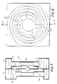
- Fig. 5 there is shown a more compact heat exchange apparatus in which the spiral pathways, not shown in detail but generally indicated by cross-hatching, of each heat exchange unit 2, 4, extend to the centre plane of the apparatus.
- the motor 26 is located in a central space constituted by hollows 40, 42 defined in the units 2, 4 respectively.
- the hollows are aligned with - effectively axial extensions of - the volutes V of the units.
- the two hollows face each other but are laterally displaced from each other to a small extent and do not communicate with one another, a partition 44 being provided, around the motor 26.
- the partition 44 extends further out so that the spiral pathways of unit 2 are not directly in communication with spiral pathways of unit 4.
- the partition has two apertures 23, 32, at the position at which the hollows 40, 42 are displaced beyond each other.
- the apertures 23, 32 constitute the transverse transfer ports from spiral pathways of units 2, 4. It will thus be appreciated, and is seen in Fig. 5, that exhaust air into unit 2 passes through aperture 23 on leaving its spiral flow path and then passes into the core of the centrifugal fan of the unit 4, thence to the outflow spiral flow path of unit 4; and that the intake air into unit 4 passes through aperture 32 on leaving its spiral flow path and thence into the core of the centrifugal fan of the unit 2, thence to the outflow spiral flow path of the unit 2.
- the embodiment of Fig. 5 is compact because of the elimination of the spacing between the heat exchange units as provided in the embodiment of Fig. 1 to 3.
- Fig. 6 shows schematically a simple embodiment in which the inner pathway 8 is effectively entirely constituted by a volute of a centrifugal impeller 18, and an outer pathway 6 is for the axial passage (into the plane of the paper) of, for example, air or water.
- Figs. 7 and 8 show an embodiment of heat exchange apparatus similar to the embodiment of Fig. 5, and in greater detail, showing the heat conductive barriers.
- the hollows 40, 42 are axial extensions of the volutes V.
- Fig. 8 shows the unit 4 (whose spiral walls are shown in dotted line) arranged upside down relative to unit 2, whose spiral walls are shown in solid line, with the transfer port 32 of unit 4 aligned with a region of the volute of unit 2, and the transfer port 23 of unit 2 aligned with a region of the volute of unit 4.
- each unit also has a outer-facing hollow 50, an axial extension of the volute, at its end which is remote from the other unit.
- the hollow 50 may receive electrical control apparatus, for example switchgear, thermostat, etc.
- each inner pathway between the dotted lines X (for unit 2), and Y (for unit 4) is a ramped region in which the inner pathway widens axially to compensate for the radial narrowing of the pathway as it leaves the volute, and prevent turbulence/stalling of the air.
- the ramp is schematically indicated by dotted lines 60 as is the nosing 62 at the end of the inner spiral pathway.
Landscapes
- Engineering & Computer Science (AREA)
- Chemical & Material Sciences (AREA)
- Combustion & Propulsion (AREA)
- Mechanical Engineering (AREA)
- Physics & Mathematics (AREA)
- Thermal Sciences (AREA)
- General Engineering & Computer Science (AREA)
- Heat-Exchange Devices With Radiators And Conduit Assemblies (AREA)
- Structures Of Non-Positive Displacement Pumps (AREA)
Claims (11)
- Heizungsgerät, bestehend aus einer ersten Heizeinheit (2) und einer zweiten Heizeinheit (4), wobei jede Heizeinheit mit einem Flussigkeitstriebrad (18, 24) und einer Hitze leitenden Wand (15) um das Flüssigkeitstriebrad herum versehen ist, und wobei jede der genannten Einheiten einen ersten Fließweg (8) um das Triebrad herum innerhalb der Wand und einen zweiten Fließweg (6) außerhalb der Wand aufweist. Die erste und zweite Einheit sind derart angeschlossen, daß der erste Fließweg der ersten Einheit über das Triebrad der ersten Einheit mit dem zweiten Fließweg der zweiten Einheit in Verbindung steht; und der erste Fließweg der zweiten Einheit steht über das Triebrad der zweiten Einheit mit dem zweiten Fließweg der ersten Einheit in Verbindung.
- Heizgerat nach Anspruch 1, wobei die Wand einer jeden Einheit spiralförmig ist und somit eine Schnecke (17) einschließt in welcher sich das Triebrad der entsprechenden Einheit befindet.
- Heizgerat nach Anspruch 2, wobei der erste Fließweg einer jeden Einheit über die Schnecke hinaus in einer Spiralgestaltung weiterläuft.
- Heizgerat nach Anspruch 2 or 3, wobei jede Einheit eine zweite spiralförmige Hitze leitende Wand (14) enthält, die als Außenwand des zweiten Fließweges der entsprechenden zweiten Einheit dient.
- Heizgerat nach einem der obigen Ansprüche, wobei die ersten und die zweiten Einheiten im wesentlichen einander gegenüber zusammenliegen, die ersten und zweiten Einheiten entsprechende Auskerbungen (19) begrenzen, welche sich seitlich abgesetzt gegenüberliegen, wobei die Einheiten zwischen sich eine Unterteilung (31) aufweisen, die so angelegt ist, daß die Verbindung zwischen dem zweiten Fließweg der ersten Einheit und dem ersten Fließweg der zweiten Einheit über eine Übergangsverbindung (23) in der Unterteilung läuft, wo sich die zweite Auskerbung seitlich über die erste Auskerbung hinauserstreckt, und über das Triebrad der zweiten Einheit.; die Verbindung zwischen dem zweiten Fließweg der zweiten Einheit und dem ersten Fließweg der ersten Einheit läuft über eine Übergangsverbindung (32) in der Unterteilung, wo sich die erste Auskerbung seitlich über die zweite Auskerbung hinauserstreckt. und über das Triebrad der ersten Einheit.
- Heizgerät nach Anspruch 5, wobei die zweite Einheit gegenüber der ersten Einheit auf den Kopf gestellt ist, und die vorgenannten Auskerbungen sind axiale Fortsetzungen entsprechender Schnecken der Einheiten, wobei jede Übergangsverbindung auf einen Abschnitt der Schnecke der anderen Einheit ausgerichtet ist.
- Heizgerät nach einem der obigen Ansprüche, wobei die Treibräder von einem gewöhnlichen Motor angetrieben werden.
- Heizgerät nach Anspruch 7, wobei der Motor zwischen den Treibrädern liegt.
- Heizgerät nach Anspruch 8 wenn von Anspruch 5 oder 6 abhängig, in dem der Motor in dem Raum zwischen den Auskerbungen liegt.
- Heizgerät nach einem der obigen Ansprüche, in dem die Hitze leitende Wand ein flexibler Streifen eines Hitze leitenden Materials ist, wobei das Gerät räumlich getrennte, parallele, aus gegenüberliegend ausgerichteten gekrümmten Rillen geformte Stützplatten hat, und daß das Gerät hergestellt wird indem der flexible Streifen des Hitze leitenden Materials der Länge nach in die gegenüber ausgerichteten gekrümmten Rillen eingeführt wird, die entsprechend in den räumlich getrennten Stützplatten vorgesehen sind.
- Verwendung des Heizgerätes nach einem der obigen Ansprüche in situ in der Außenwand eines Gebäudes zum Zwecke des Hitzeaustausches zwischen Absaugluft aus dem Innern des Gebäudes and Ansauglauf von außen.
Applications Claiming Priority (3)
| Application Number | Priority Date | Filing Date | Title |
|---|---|---|---|
| GB898918446A GB8918446D0 (en) | 1989-08-12 | 1989-08-12 | Heat exchange apparatus |
| GB8918446 | 1989-08-12 | ||
| PCT/GB1990/001272 WO1991002928A1 (en) | 1989-08-12 | 1990-08-13 | Heat exchange apparatus |
Publications (2)
| Publication Number | Publication Date |
|---|---|
| EP0491741A1 EP0491741A1 (de) | 1992-07-01 |
| EP0491741B1 true EP0491741B1 (de) | 1995-06-21 |
Family
ID=10661552
Family Applications (1)
| Application Number | Title | Priority Date | Filing Date |
|---|---|---|---|
| EP90912986A Expired - Lifetime EP0491741B1 (de) | 1989-08-12 | 1990-08-13 | Wärmeübertragungsgerät |
Country Status (6)
| Country | Link |
|---|---|
| US (1) | US5220955A (de) |
| EP (1) | EP0491741B1 (de) |
| AU (1) | AU6281290A (de) |
| DE (1) | DE69020354D1 (de) |
| GB (1) | GB8918446D0 (de) |
| WO (1) | WO1991002928A1 (de) |
Families Citing this family (25)
| Publication number | Priority date | Publication date | Assignee | Title |
|---|---|---|---|---|
| US5326537A (en) * | 1993-01-29 | 1994-07-05 | Cleary James M | Counterflow catalytic device |
| US5490557A (en) * | 1994-10-07 | 1996-02-13 | Trent Metals Limited | Housing for a heat recovery ventilator with fans hingedly mounted to housing |
| GB2296968A (en) * | 1994-12-02 | 1996-07-17 | Thermal Technology | Heat exchange ventilator |
| DE19654704A1 (de) * | 1996-12-30 | 1998-07-02 | Walter Foeckersperger | Raumbelüftungsverfahren |
| JP3574727B2 (ja) * | 1997-03-31 | 2004-10-06 | 国際技術開発株式会社 | 熱交換装置 |
| US5855320A (en) * | 1997-04-17 | 1999-01-05 | Nutech Energy Systems Inc. | Combined furnace and heat recovery system |
| DE19743509A1 (de) * | 1997-10-01 | 1999-04-08 | Bosch Siemens Hausgeraete | Haushalt-Wäschetrockner mit einem Wäschefeuchtigkeit abführenden Prozeßluft-Kreis |
| US6742582B1 (en) * | 2000-01-20 | 2004-06-01 | Vent-Rite Valve Corp. | Modular climate control unit |
| AU2003201182B2 (en) * | 2002-01-03 | 2008-05-01 | Pax Scientific, Inc. | Vortex ring generator |
| AUPR982502A0 (en) * | 2002-01-03 | 2002-01-31 | Pax Fluid Systems Inc. | A heat exchanger |
| AUPR982302A0 (en) * | 2002-01-03 | 2002-01-31 | Pax Fluid Systems Inc. | A fluid flow controller |
| AU2003903386A0 (en) * | 2003-07-02 | 2003-07-17 | Pax Scientific, Inc | Fluid flow control device |
| CA2544516C (en) * | 2003-11-04 | 2014-04-29 | Pax Scientific, Inc. | Fluid circulation system |
| CA2554808A1 (en) | 2004-01-30 | 2005-08-11 | Pax Scientific, Inc. | Housing for a centrifugal fan, pump or turbine |
| CN1985093A (zh) * | 2004-01-30 | 2007-06-20 | 百思科技公司 | 用于离心通风机、泵或涡轮机的机罩 |
| USD570996S1 (en) | 2006-09-25 | 2008-06-10 | Pax Scientific, Inc. | Rotor |
| US8328522B2 (en) | 2006-09-29 | 2012-12-11 | Pax Scientific, Inc. | Axial flow fan |
| USD570999S1 (en) | 2006-11-22 | 2008-06-10 | Pax Scientific, Inc. | Rotor |
| US20090308472A1 (en) * | 2008-06-15 | 2009-12-17 | Jayden David Harman | Swirl Inducer |
| IN2012DN00274A (de) | 2009-06-24 | 2015-05-08 | Valorbec Soc En Commandite Representee Par Gestion Valeo S E C | |
| US7952857B1 (en) | 2010-02-22 | 2011-05-31 | Motley Gregory O | Arc-resistant switchgear enclosure with ambient air ventilation system |
| WO2014111742A1 (en) * | 2013-01-21 | 2014-07-24 | Carrier Corporation | Advanced air terminal |
| US10557391B1 (en) * | 2017-05-18 | 2020-02-11 | Advanced Cooling Technologies, Inc. | Incineration system and process |
| CN107504533B (zh) * | 2017-08-23 | 2020-03-31 | 上海多环油烟净化设备有限公司 | 两用式循环净化机 |
| TWI769612B (zh) * | 2020-11-02 | 2022-07-01 | 國立成功大學 | 渦捲式加熱裝置 |
Family Cites Families (19)
| Publication number | Priority date | Publication date | Assignee | Title |
|---|---|---|---|---|
| DE180784C (de) * | ||||
| GB221714A (en) * | 1923-12-20 | 1924-09-18 | Christian Lorenzen | Improvements in or relating to gas turbines |
| US1799039A (en) * | 1929-09-16 | 1931-03-31 | Conejos Anthony | Heat extractor |
| GB433004A (en) * | 1934-06-27 | 1935-08-07 | Soren Jorgen Jensen | Apparatus for heating or cooling of liquids |
| NL48051C (de) * | 1937-02-25 | |||
| GB745914A (en) * | 1953-01-28 | 1956-03-07 | William Helmore | Improvements in or relating to heat exchangers |
| US2768508A (en) * | 1953-03-30 | 1956-10-30 | Robert H Guyton | Refrigerator condenser |
| GB778541A (en) * | 1955-01-31 | 1957-07-10 | Rosenblads Patenter Ab | Heat-exchanger of the type having spiral or volute passages |
| US3854530A (en) * | 1969-12-29 | 1974-12-17 | E Jouet | Heat exchanger |
| SE7415821L (sv) * | 1974-12-17 | 1976-06-18 | Blomgren Ab Ventilation | Korsstromsvermevexlare |
| DE3006318C2 (de) * | 1980-02-20 | 1986-08-07 | MLL Maximal Lärmschutz-Lüftungen GmbH | Lüftungsvorrichtung |
| GB2076133A (en) * | 1980-02-26 | 1981-11-25 | Strentex Fabrics Ltd | A respiratory heat exchanger for low temperature environments |
| JPS5915739A (ja) * | 1982-07-16 | 1984-01-26 | Matsushita Electric Ind Co Ltd | 熱交換換気装置 |
| US4574872A (en) * | 1982-11-04 | 1986-03-11 | Matsushita Electric Industrial Co., Ltd. | Heat exchanger apparatus |
| DE3319521A1 (de) * | 1983-05-28 | 1984-11-29 | Kienzle Apparate Gmbh, 7730 Villingen-Schwenningen | Waermeaustauscher fuer fluessige medien |
| DE3505789A1 (de) * | 1985-02-20 | 1986-08-21 | Grote, Paul, 2901 Friedrichsfehn | Spiralwaermetauscher |
| DE3509226C2 (de) * | 1985-03-14 | 1997-03-27 | Sen Alexander Faller | Wärmetauscher |
| US4711293A (en) * | 1986-08-28 | 1987-12-08 | Kabushiki Kaisha Toshiba | Ventilator of the heat exchange type |
| DE3643496C2 (de) * | 1986-12-19 | 1994-06-09 | Timmer Ingbuero Gmbh | Strömungsmaschine zum Fördern von zwei Medien mit Wärmeübertragung zwischen den Medien |
-
1989
- 1989-08-12 GB GB898918446A patent/GB8918446D0/en active Pending
-
1990
- 1990-08-13 DE DE69020354T patent/DE69020354D1/de not_active Expired - Lifetime
- 1990-08-13 AU AU62812/90A patent/AU6281290A/en not_active Abandoned
- 1990-08-13 US US07/834,333 patent/US5220955A/en not_active Expired - Fee Related
- 1990-08-13 WO PCT/GB1990/001272 patent/WO1991002928A1/en not_active Ceased
- 1990-08-13 EP EP90912986A patent/EP0491741B1/de not_active Expired - Lifetime
Also Published As
| Publication number | Publication date |
|---|---|
| AU6281290A (en) | 1991-04-03 |
| EP0491741A1 (de) | 1992-07-01 |
| DE69020354D1 (de) | 1995-07-27 |
| WO1991002928A1 (en) | 1991-03-07 |
| US5220955A (en) | 1993-06-22 |
| GB8918446D0 (en) | 1989-09-20 |
Similar Documents
| Publication | Publication Date | Title |
|---|---|---|
| EP0491741B1 (de) | Wärmeübertragungsgerät | |
| US7334629B2 (en) | Ventilating system, heat exchanger and methods | |
| US6931883B2 (en) | Two stage indirect evaporative cooling system | |
| JPS6335900B2 (de) | ||
| US20200300498A1 (en) | A compact heat recovery ventilation system | |
| WO2005103576A2 (en) | Heat and energy recovery ventilators and methods of use | |
| WO2013075722A1 (en) | A modular ventilation system with energy recovery | |
| EP2306108A1 (de) | Belüftungsanordnung | |
| US4572282A (en) | Ventilation system for building | |
| WO2019050484A1 (en) | VENTILATION DEVICE | |
| JPS6136641A (ja) | 空調換気装置 | |
| WO2017192038A1 (en) | Recuperator for exchanging energy between two air flows | |
| WO1994018507A1 (en) | Arrangement relating to a regenerative heat exchanger for ventilation | |
| FI96238C (fi) | Ilmanvaihtolaite huonetiloissa samanaikaisesti tapahtuvaa ilman syöttämistä ja poistamista varten | |
| EP2965020B1 (de) | Anlage zum konditionieren der luft in einem gebäude | |
| JP4325813B2 (ja) | 住宅用ダクトレス換気システム | |
| CN112443913B (zh) | 吸湿模块、加湿装置 | |
| JP2575861B2 (ja) | 空調換気扇 | |
| WO2008051098A2 (en) | A heat exchanger, a heat sink and a heat exchange system | |
| EP4722611A1 (de) | Wärmerückgewinnungseinheit und verfahren zu dessen betrieb | |
| WO1999013283A1 (en) | Heat exchanger | |
| CN219589063U (zh) | 一种新风装置及具有其的新风空调 | |
| JP2586746B2 (ja) | 天井冷暖房システム | |
| KR20260049846A (ko) | 건물의 벽에 설치되기 위한 환기 시스템 및 이를 구비한 건물 | |
| JPS6110109Y2 (de) |
Legal Events
| Date | Code | Title | Description |
|---|---|---|---|
| PUAI | Public reference made under article 153(3) epc to a published international application that has entered the european phase |
Free format text: ORIGINAL CODE: 0009012 |
|
| 17P | Request for examination filed |
Effective date: 19920312 |
|
| AK | Designated contracting states |
Kind code of ref document: A1 Designated state(s): AT BE CH DE DK ES FR GB IT LI LU NL SE |
|
| RBV | Designated contracting states (corrected) |
Designated state(s): DE ES FR GB IT |
|
| 17Q | First examination report despatched |
Effective date: 19930721 |
|
| GRAA | (expected) grant |
Free format text: ORIGINAL CODE: 0009210 |
|
| AK | Designated contracting states |
Kind code of ref document: B1 Designated state(s): DE ES FR GB IT |
|
| PG25 | Lapsed in a contracting state [announced via postgrant information from national office to epo] |
Ref country code: IT Free format text: LAPSE BECAUSE OF FAILURE TO SUBMIT A TRANSLATION OF THE DESCRIPTION OR TO PAY THE FEE WITHIN THE PRESCRIBED TIME-LIMIT;WARNING: LAPSES OF ITALIAN PATENTS WITH EFFECTIVE DATE BEFORE 2007 MAY HAVE OCCURRED AT ANY TIME BEFORE 2007. THE CORRECT EFFECTIVE DATE MAY BE DIFFERENT FROM THE ONE RECORDED. Effective date: 19950621 Ref country code: ES Free format text: THE PATENT HAS BEEN ANNULLED BY A DECISION OF A NATIONAL AUTHORITY Effective date: 19950621 Ref country code: FR Effective date: 19950621 |
|
| REF | Corresponds to: |
Ref document number: 69020354 Country of ref document: DE Date of ref document: 19950727 |
|
| PG25 | Lapsed in a contracting state [announced via postgrant information from national office to epo] |
Ref country code: DE Effective date: 19950922 |
|
| EN | Fr: translation not filed | ||
| PLBE | No opposition filed within time limit |
Free format text: ORIGINAL CODE: 0009261 |
|
| STAA | Information on the status of an ep patent application or granted ep patent |
Free format text: STATUS: NO OPPOSITION FILED WITHIN TIME LIMIT |
|
| 26N | No opposition filed | ||
| PGFP | Annual fee paid to national office [announced via postgrant information from national office to epo] |
Ref country code: GB Payment date: 19970714 Year of fee payment: 8 |
|
| PG25 | Lapsed in a contracting state [announced via postgrant information from national office to epo] |
Ref country code: GB Free format text: LAPSE BECAUSE OF NON-PAYMENT OF DUE FEES Effective date: 19980813 |
|
| GBPC | Gb: european patent ceased through non-payment of renewal fee |
Effective date: 19980813 |