EP0498536A2 - Valve disc and drive shaft assembly - Google Patents
Valve disc and drive shaft assembly Download PDFInfo
- Publication number
- EP0498536A2 EP0498536A2 EP92300347A EP92300347A EP0498536A2 EP 0498536 A2 EP0498536 A2 EP 0498536A2 EP 92300347 A EP92300347 A EP 92300347A EP 92300347 A EP92300347 A EP 92300347A EP 0498536 A2 EP0498536 A2 EP 0498536A2
- Authority
- EP
- European Patent Office
- Prior art keywords
- shaft
- bore
- tang
- disc
- base
- Prior art date
- Legal status (The legal status is an assumption and is not a legal conclusion. Google has not performed a legal analysis and makes no representation as to the accuracy of the status listed.)
- Withdrawn
Links
Images




Classifications
-
- F—MECHANICAL ENGINEERING; LIGHTING; HEATING; WEAPONS; BLASTING
- F16—ENGINEERING ELEMENTS AND UNITS; GENERAL MEASURES FOR PRODUCING AND MAINTAINING EFFECTIVE FUNCTIONING OF MACHINES OR INSTALLATIONS; THERMAL INSULATION IN GENERAL
- F16K—VALVES; TAPS; COCKS; ACTUATING-FLOATS; DEVICES FOR VENTING OR AERATING
- F16K1/00—Lift valves or globe valves, i.e. cut-off apparatus with closure members having at least a component of their opening and closing motion perpendicular to the closing faces
- F16K1/16—Lift valves or globe valves, i.e. cut-off apparatus with closure members having at least a component of their opening and closing motion perpendicular to the closing faces with pivoted closure-members
- F16K1/18—Lift valves or globe valves, i.e. cut-off apparatus with closure members having at least a component of their opening and closing motion perpendicular to the closing faces with pivoted closure-members with pivoted discs or flaps
- F16K1/22—Lift valves or globe valves, i.e. cut-off apparatus with closure members having at least a component of their opening and closing motion perpendicular to the closing faces with pivoted closure-members with pivoted discs or flaps with axis of rotation crossing the valve member, e.g. butterfly valves
Definitions
- This invention relates to a valve disc and drive shaft assembly particularly for a butterfly valve.
- the disc is cast to its general shape and then a diametrically arranged bore is formed by drilling. This bore extends across the whole diameter of the disc and receives the drive shaft by means of which the disc is rotated to open or close the valve.
- one or more pins are provided radially with respect to the shaft axis and inserted through holes in the disc into blind apertures on the shaft.
- a valve disc and drive shaft assembly comprises a disc formed with a blind bore of circular cross-section extending radially inwards from the disc periphery and a shaft of circular cross-section located in said bore having a diameter substantially equal to that of the bore, the end of the shaft or the base of the bore being provided with a tang extending parallel to the shaft rotational axis and diametrically across at least part of the shaft or base perpendicularly to the plane of the disc and fitting in a corresponding recess provided at the base of the bore or the end of the shaft respectively.
- the tang and recess are generally rectangular, preferably with rounded ends, for ease of manufacture.
- the tang may be formed integrally with or separately from the shaft or base and be an interference fit in an aperture formed in the base of the bore or end of the shaft respectively.
- valve comprises a central valve disc 10, an upper socket 12 and a lower socket 14, all cast as a single unit and then subsequently machined to its final shape, an upper drive shaft 16 and a lower supporting shaft 18.
- the upper drive shaft 16 is housed in a conventional tubular housing 20 in the body of the valve and is provided with a seal 22 in a conventional manner. Details of this will not be given because they are not relevant to the present invention.
- a handle 24 is provided at the upper end of the drive shaft 16 in order that the valve may be opened and closed.
- the upper socket 12 of the valve disc 10, shown particularly in Figure 6, is provided with a shallow main bore 26, accurately machined to the required size and shape and, in the base 29 of the main bore, an elongated recess 28 extending diametrically across the whole of the base of the main bore, the longer axis of the recess being perpendicular to the central plane of the disc.
- the recess 28 is generally rectangular in plan but with semi-circular ends.
- the end 30 of the drive shaft 16 is accurately machined so that it is generally at right angles to the shaft axis 0-0 and it locates in the main bore 26 of the upper socket 12 so that the shaft axis 0-0 is in alignment with the axis of the main bore.
- Protruding from the end of the shaft is a tang 32 having a configuration corresponding to the recess 28 at the base 29 of the main bore 26 in the upper socket 12.
- This tang 32 is a tight sliding fit in the recess 28, the longer axis of the tang (i.e. the tang dimension measured perpendicularly to the plane of the disc) being slightly shorter than the longer axis of the recess.
- a lower socket 14 formed with a shallow bore 34 and having a conical base 36 formed by a drilling operation.
- This bore 34 formed in the lower socket receives the upper end 38 of the lower supporting shaft 18.
- the lower supporting shaft 18 and the lower socket act as a bearing for the valve disc.
- the bore 34 in the lower socket 14 and the upper end of the supporting shaft 18 accurately locate the valve disc 10 in the required position in the valve.
- the periphery of the valve disc Adjacent the upper and lower sockets the periphery of the valve disc is formed with two flat surfaces 40, 42 in a conventional manner and the two generally semi-circular parts of the periphery of the valve disc are machined to have a profiled edge (generally semi-circular in cross-section) as shown particularly at 44 in Figure 3 to provide sealing engagement with a rubber seal formed within the bore of the main valve (not shown).
- the tang on the end face of the drive shaft is not integrally formed therewith but is in the form of a separate member which is an interference fit in an appropriately shaped aperture formed in the end face of the shaft.
- the major axis of the tang is slightly shorter than the major axis of the recess, when the disc is subjected to a high pressure and caused to bend the tang has freedom to move slightly with respect to the recess.
- the disc is therefore not constrained by the shaft in the bending mode. Thus a lower torque is needed to rotate the shaft and thus open the valve.
- the shaft is operated by an actuator, the size of actuator may be reduced.
- the diameter of the shaft may also be reduced because less shaft strength is required. Thus overall there may be a saving in energy and material cost.
- the two shafts 16 and 18 are shaped so as to provide shortened lengths 71 of shaft surface engaging the interior surfaces of the bores 26 and 34. This is achieved by providing two frusto conical surfaces 70, 72 immediately adjacent the ends of the shafts, and spaced apart from these a groove 75 having tapered sides 74 and 76, the side 76 further from the shaft end making only a small angle, about 5°, with the shaft axis.
- the shortened lengths 71 allows the disc to deflect (or float) between the shafts 16 and 18 when under a pressure load, without constraint by the shafts 16 and 18 to disc bending. Consequently, this keeps any increase in the effort required to rotate the shaft to a low value because the bending movement on each shaft itself has a low value.
- valve disc in all forms of the invention is not pierced in any way on either of its main surfaces 60, 64 the likelihood of any leakage occurring from one side of the disc to the other or to the the exterior of the valve along the surface of the drive shaft 16 is eliminated.
- the tang is aligned as described so that deflection of the disc, when in the closed position, due to the forces of the fluid flowing through the valve, tends to move along the tang and reduce the sideways loading on the shaft, which in turn prevents an excessive increase in the effort required to rotate the shaft.
Landscapes
- Engineering & Computer Science (AREA)
- General Engineering & Computer Science (AREA)
- Mechanical Engineering (AREA)
- Lift Valve (AREA)
Abstract
A valve disc (10) and drive shaft (16) assembly wherein the end of the drive shaft (16) seats in a blind bore (26) at the periphery of the valve disc. The end (30) of the shaft (16) or the base (29) of the bore (26) is formed with a tang (32), extending perpendicularly to the plane of the disc (10), seating in an elongated recess (28) in the base (29) of the bore (26) or end (30) of the shaft (16) respectively.
Description
- This invention relates to a valve disc and drive shaft assembly particularly for a butterfly valve. In a known form of butterfly valve, the disc is cast to its general shape and then a diametrically arranged bore is formed by drilling. This bore extends across the whole diameter of the disc and receives the drive shaft by means of which the disc is rotated to open or close the valve. To prevent the shaft rotating in the bore one or more pins are provided radially with respect to the shaft axis and inserted through holes in the disc into blind apertures on the shaft.
- However, it has been found that sometimes the joint between a pin and a disc is not properly formed or becomes damaged and leakage occurs either through the disc from one side to the other, or from the interior to the exterior of the valve along a leakage path alongside the drive shaft.
- When in the closed condition the disc of a butterfly valve disc is often subjected to a considerable pressure caused by the fluid acting on one side. As a result the disc may bend and very high bending movements are applied to the shaft. To open the valve a large torque has to be applied to the shaft and additionally in order to support these loads the shaft has to be of relatively large diameter.
- It is an object of the present invention to provide a valve disc and drive shaft assembly with a relatively simple means for non-rotatably securing the disc to the shaft and to reduce or overcome the above disadvantages.
- In accordance with the present invention, a valve disc and drive shaft assembly comprises a disc formed with a blind bore of circular cross-section extending radially inwards from the disc periphery and a shaft of circular cross-section located in said bore having a diameter substantially equal to that of the bore, the end of the shaft or the base of the bore being provided with a tang extending parallel to the shaft rotational axis and diametrically across at least part of the shaft or base perpendicularly to the plane of the disc and fitting in a corresponding recess provided at the base of the bore or the end of the shaft respectively.
- Preferably the tang and recess are generally rectangular, preferably with rounded ends, for ease of manufacture. The tang may be formed integrally with or separately from the shaft or base and be an interference fit in an aperture formed in the base of the bore or end of the shaft respectively.
- One embodiment of the invention will now be described by way of example with reference to the accompanying drawings of which:-
- Figure 1 is a general cross-sectional view of the valve disc and drive shaft assembly and associated valve components;
- Figure 2 is a side view of the valve disc;
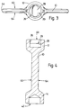
- Figure 3 is a plan view of the valve disc shown in Figure 2;
- Figure 4 is a cross-sectional view of the valve disc shown in Figure 2;
- Figure 5 is a perspective view of the lower end of the drive shaft;
- Figure 6 is a perspective view of half of the upper socket of the valve disc;
- Figure 7 shows a modified form of the assembly shown in Figure 1;
- Figure 8 shows on an enlarged scale the end of the drive shaft; and
- Figure 9 shows on an enlarged scale the end of the supporting shaft.
- As can be seen in the drawings the valve comprises a
central valve disc 10, anupper socket 12 and alower socket 14, all cast as a single unit and then subsequently machined to its final shape, anupper drive shaft 16 and a lower supportingshaft 18. - The
upper drive shaft 16 is housed in a conventionaltubular housing 20 in the body of the valve and is provided with aseal 22 in a conventional manner. Details of this will not be given because they are not relevant to the present invention. Ahandle 24 is provided at the upper end of thedrive shaft 16 in order that the valve may be opened and closed. - The
upper socket 12 of thevalve disc 10, shown particularly in Figure 6, is provided with a shallowmain bore 26, accurately machined to the required size and shape and, in thebase 29 of the main bore, anelongated recess 28 extending diametrically across the whole of the base of the main bore, the longer axis of the recess being perpendicular to the central plane of the disc. Therecess 28 is generally rectangular in plan but with semi-circular ends. - The
end 30 of thedrive shaft 16 is accurately machined so that it is generally at right angles to the shaft axis 0-0 and it locates in themain bore 26 of theupper socket 12 so that the shaft axis 0-0 is in alignment with the axis of the main bore. Protruding from the end of the shaft is atang 32 having a configuration corresponding to therecess 28 at thebase 29 of themain bore 26 in theupper socket 12. Thistang 32 is a tight sliding fit in therecess 28, the longer axis of the tang (i.e. the tang dimension measured perpendicularly to the plane of the disc) being slightly shorter than the longer axis of the recess. - Diametrically opposite the
upper socket 12 of thevalve disc 10 is alower socket 14 formed with ashallow bore 34 and having aconical base 36 formed by a drilling operation. Thisbore 34 formed in the lower socket receives theupper end 38 of the lower supportingshaft 18. The lower supportingshaft 18 and the lower socket act as a bearing for the valve disc. Thebore 34 in thelower socket 14 and the upper end of the supportingshaft 18 accurately locate thevalve disc 10 in the required position in the valve. - Adjacent the upper and lower sockets the periphery of the valve disc is formed with two
flat surfaces - As a first modification to the present invention (not illustrated) the tang on the end face of the drive shaft is not integrally formed therewith but is in the form of a separate member which is an interference fit in an appropriately shaped aperture formed in the end face of the shaft.
- Since the major axis of the tang is slightly shorter than the major axis of the recess, when the disc is subjected to a high pressure and caused to bend the tang has freedom to move slightly with respect to the recess. The disc is therefore not constrained by the shaft in the bending mode. Thus a lower torque is needed to rotate the shaft and thus open the valve. If the shaft is operated by an actuator, the size of actuator may be reduced. In addition the diameter of the shaft may also be reduced because less shaft strength is required. Thus overall there may be a saving in energy and material cost.
- In a second modification of the invention shown in Figures 7, 8 and 9 the two
shafts lengths 71 of shaft surface engaging the interior surfaces of thebores conical surfaces groove 75 having taperedsides side 76 further from the shaft end making only a small angle, about 5°, with the shaft axis. - The shortened
lengths 71 allows the disc to deflect (or float) between theshafts shafts - Since the valve disc in all forms of the invention is not pierced in any way on either of its
main surfaces drive shaft 16 is eliminated. The tang is aligned as described so that deflection of the disc, when in the closed position, due to the forces of the fluid flowing through the valve, tends to move along the tang and reduce the sideways loading on the shaft, which in turn prevents an excessive increase in the effort required to rotate the shaft.
Claims (9)
- A valve disc (10) and drive shaft assembly (16) characterised by comprising a disc (10) formed with a blind bore (26) of circular cross-section extending radially inwards from the disc periphery and a shaft (16) of circular cross-section located in said bore (26) having a diameter substantially equal to that of the bore (26), the end (30) of the shaft (16) or the base (29) of the bore (26) being provided with a tang (32) extending parallel to the shaft rotational axis and diametrically across at least part of the shaft (16) or base (29) perpendicularly to the plane of the disc (10) and fitting in an elongated recess (28) provided at the base (29) of the bore (26) or the end (30) of the shaft (16) respectively.
- An assembly according to Claim 1 characterised in that the tang (32) and recess (28) are generally rectangular.
- An assembly according to Claim 1 characterised in that the tang (32) and recess (28) are generally rectangular and have rounded ends.
- An assembly according to any one of the preceding claims characterised in that the tang (32) is integral with the shaft (10).
- An assembly according to any one of Claims 1-3 characterised in that the tang (32) is integral with the base (29) of the bore (26).
- An assembly according to any one of Claims 1-3 characterised in that the tang (32) is formed separately from the shaft (10) or base (29) and is an interference fit in an aperture formed in the end (30) of the shaft (10) or base (29) of the bore (26) respectively.
- An assembly according to any one of the preceding claims characterised in that the longer axis of the tang (32) is shorter than the longer axis of the recess (28).
- An assembly according to any one of the preceding claims characterised in that the shaft (10) comprises a groove (75) spaced apart from the end (30) thereof and extending around the shaft circumference.
- An assembly according to Claim 8 characterised in that the groove (75) has tapered sides (74,76).
Applications Claiming Priority (2)
| Application Number | Priority Date | Filing Date | Title |
|---|---|---|---|
| GB9102003 | 1991-01-30 | ||
| GB919102003A GB9102003D0 (en) | 1991-01-30 | 1991-01-30 | Valve disc and drive shaft assembly |
Publications (2)
| Publication Number | Publication Date |
|---|---|
| EP0498536A2 true EP0498536A2 (en) | 1992-08-12 |
| EP0498536A3 EP0498536A3 (en) | 1992-10-14 |
Family
ID=10689238
Family Applications (1)
| Application Number | Title | Priority Date | Filing Date |
|---|---|---|---|
| EP19920300347 Withdrawn EP0498536A3 (en) | 1991-01-30 | 1992-01-15 | Valve disc and drive shaft assembly |
Country Status (4)
| Country | Link |
|---|---|
| US (1) | US5226630A (en) |
| EP (1) | EP0498536A3 (en) |
| GB (2) | GB9102003D0 (en) |
| IN (1) | IN176498B (en) |
Cited By (3)
| Publication number | Priority date | Publication date | Assignee | Title |
|---|---|---|---|---|
| DE4236144A1 (en) * | 1992-10-27 | 1994-04-28 | Babcock Energie Umwelt | Throttle valve with housing and flap valve - has shaft location pins with spherical heads connected to housing and mounting sleeve |
| EP1811211A3 (en) * | 2006-01-21 | 2007-11-07 | Erhard GmbH & Co. KG | Valve for the cut-off or regulation of a fluide |
| WO2014072094A1 (en) * | 2012-11-09 | 2014-05-15 | Pierburg Gmbh | Flap device for an internal combustion engine or an electric vehicle |
Families Citing this family (1)
| Publication number | Priority date | Publication date | Assignee | Title |
|---|---|---|---|---|
| US20050184268A1 (en) * | 2004-02-25 | 2005-08-25 | Siemens Vdo Automotive, Inc. | Laser welded butterfly valve blade |
Family Cites Families (12)
| Publication number | Priority date | Publication date | Assignee | Title |
|---|---|---|---|---|
| DE1072037B (en) * | 1959-12-24 | |||
| AT209123B (en) * | 1956-09-06 | 1960-05-25 | Rockwell Mfg Co | Rooster |
| US3192945A (en) * | 1961-10-26 | 1965-07-06 | Victaulic Co Of America | Butterfly valves |
| US3118465A (en) * | 1963-02-18 | 1964-01-21 | Scaramucci Domer | Disc valve |
| US3341170A (en) * | 1964-03-25 | 1967-09-12 | Fmc Corp | Valve |
| FR1464861A (en) * | 1965-11-25 | 1967-01-06 | Forges & Acieries Du Saut Du T | Ball valve |
| DE2626666C2 (en) * | 1976-06-15 | 1986-05-22 | Josef 6200 Wiesbaden Nemetz | Butterfly valve |
| US4293163A (en) * | 1977-04-26 | 1981-10-06 | Texas Iron Works, Inc. | Valve for closing the fluid passage of a well bore tubular member with balanced operating arrangement |
| DE2724007A1 (en) * | 1977-05-27 | 1978-12-07 | Wurzer Lothar | Stop or non-return valve for fluids - has disc hub fitting round inwards protruding bushes fixed in housing |
| IT1138544B (en) * | 1981-09-02 | 1986-09-17 | Nuovo Pignone Spa | PERFECTED KEY FOR BALL VALVES OPERATION |
| US4519414A (en) * | 1983-01-18 | 1985-05-28 | Industrial De Valvulas, S.A. De C.V. | Mechanically balanced tapered plug valve |
| US4756507A (en) * | 1987-07-06 | 1988-07-12 | Mcandrew William J | Ball or plug valve stem extension and lock mechanism |
-
1991
- 1991-01-30 GB GB919102003A patent/GB9102003D0/en active Pending
-
1992
- 1992-01-15 GB GB9201254A patent/GB2252395B/en not_active Expired - Fee Related
- 1992-01-15 EP EP19920300347 patent/EP0498536A3/en not_active Withdrawn
- 1992-01-27 US US07/826,431 patent/US5226630A/en not_active Expired - Lifetime
- 1992-02-27 IN IN46CA1992 patent/IN176498B/en unknown
Cited By (6)
| Publication number | Priority date | Publication date | Assignee | Title |
|---|---|---|---|---|
| DE4236144A1 (en) * | 1992-10-27 | 1994-04-28 | Babcock Energie Umwelt | Throttle valve with housing and flap valve - has shaft location pins with spherical heads connected to housing and mounting sleeve |
| DE4236144B4 (en) * | 1992-10-27 | 2005-07-21 | Babcock Borsig Power Systems Gmbh | butterfly valve |
| EP1811211A3 (en) * | 2006-01-21 | 2007-11-07 | Erhard GmbH & Co. KG | Valve for the cut-off or regulation of a fluide |
| RU2423635C2 (en) * | 2006-01-21 | 2011-07-10 | Эрхард Гмбх Унд Ко.Кг | Accessories for shutting-off and control of medium |
| WO2014072094A1 (en) * | 2012-11-09 | 2014-05-15 | Pierburg Gmbh | Flap device for an internal combustion engine or an electric vehicle |
| US9851123B2 (en) | 2012-11-09 | 2017-12-26 | Pierburg Gmbh | Flap device for an internal combustion engine or an electric vehicle |
Also Published As
| Publication number | Publication date |
|---|---|
| GB9102003D0 (en) | 1991-03-13 |
| GB9201254D0 (en) | 1992-03-11 |
| GB2252395A (en) | 1992-08-05 |
| EP0498536A3 (en) | 1992-10-14 |
| IN176498B (en) | 1996-06-22 |
| US5226630A (en) | 1993-07-13 |
| GB2252395B (en) | 1994-11-02 |
Similar Documents
| Publication | Publication Date | Title |
|---|---|---|
| EP2299152A2 (en) | Ball valve with anti-rotational pressure plate | |
| US6604448B2 (en) | Dual end stop actuator and method | |
| US4768750A (en) | Valve joint connection | |
| EP0160576A1 (en) | Wafer check valves | |
| US10228070B2 (en) | Check valves | |
| US6988709B2 (en) | Bearing retainer for trunnion mounted ball valve | |
| US6213141B1 (en) | Rotary valve apparatus and associated methods | |
| US5743512A (en) | Wedge lock butterfly valve | |
| US4711427A (en) | Apparatus for connecting a valve element to a valve stem | |
| US5226630A (en) | Valve disc and drive shaft assembly | |
| US5388807A (en) | Modular butterfly valve | |
| US4632140A (en) | Top entry ball valve | |
| EP0493921A1 (en) | Valve disc and drive shaft assembly | |
| US5297778A (en) | Valve disc and drive shaft assembly | |
| EP1825176B1 (en) | Axially energisable ball valve | |
| US20110198527A1 (en) | Axially energisable ball valve | |
| US7243901B2 (en) | Rotary valve apparatus and associated methods | |
| CN112789435A (en) | Multi-valve seat gate valve | |
| CN102395823A (en) | Fluid valves having adjustable sealing characteristics | |
| EP0442972A1 (en) | FLAP VALVE WITHOUT PIVOT. | |
| EP0461294A1 (en) | Stop valve | |
| TWM517277U (en) | Dual-wedge-shaped butterfly valve structure | |
| KR820001288B1 (en) | Rotary valve | |
| JP2571423Y2 (en) | Top entry type three-way switching ball valve | |
| GB2237099A (en) | Valve assembly |
Legal Events
| Date | Code | Title | Description |
|---|---|---|---|
| PUAI | Public reference made under article 153(3) epc to a published international application that has entered the european phase |
Free format text: ORIGINAL CODE: 0009012 |
|
| AK | Designated contracting states |
Kind code of ref document: A2 Designated state(s): DE ES FR GB IT NL |
|
| PUAL | Search report despatched |
Free format text: ORIGINAL CODE: 0009013 |
|
| AK | Designated contracting states |
Kind code of ref document: A3 Designated state(s): DE ES FR GB IT NL |
|
| 17P | Request for examination filed |
Effective date: 19930413 |
|
| 17Q | First examination report despatched |
Effective date: 19940705 |
|
| RBV | Designated contracting states (corrected) |
Designated state(s): DE ES FR IT NL |
|
| 18W | Application withdrawn |
Withdrawal date: 19960302 |