EP0506171A1 - Pneumatic device for cleaning air filters - Google Patents
Pneumatic device for cleaning air filters Download PDFInfo
- Publication number
- EP0506171A1 EP0506171A1 EP92200750A EP92200750A EP0506171A1 EP 0506171 A1 EP0506171 A1 EP 0506171A1 EP 92200750 A EP92200750 A EP 92200750A EP 92200750 A EP92200750 A EP 92200750A EP 0506171 A1 EP0506171 A1 EP 0506171A1
- Authority
- EP
- European Patent Office
- Prior art keywords
- duct
- filter
- filters
- compressed air
- air
- Prior art date
- Legal status (The legal status is an assumption and is not a legal conclusion. Google has not performed a legal analysis and makes no representation as to the accuracy of the status listed.)
- Granted
Links
- 238000004140 cleaning Methods 0.000 title claims abstract description 18
- 230000033001 locomotion Effects 0.000 claims abstract description 11
- XLYOFNOQVPJJNP-UHFFFAOYSA-N water Substances O XLYOFNOQVPJJNP-UHFFFAOYSA-N 0.000 claims abstract description 4
- 239000013013 elastic material Substances 0.000 claims 1
- 239000000428 dust Substances 0.000 abstract description 17
- 239000002245 particle Substances 0.000 abstract description 2
- 239000000203 mixture Substances 0.000 abstract 1
- 241000196324 Embryophyta Species 0.000 description 3
- 238000006243 chemical reaction Methods 0.000 description 2
- 239000012535 impurity Substances 0.000 description 2
- 239000000463 material Substances 0.000 description 2
- 230000001172 regenerating effect Effects 0.000 description 2
- 229920001875 Ebonite Polymers 0.000 description 1
- 244000126968 Kalanchoe pinnata Species 0.000 description 1
- 230000002159 abnormal effect Effects 0.000 description 1
- 238000004378 air conditioning Methods 0.000 description 1
- 230000005540 biological transmission Effects 0.000 description 1
- 230000000903 blocking effect Effects 0.000 description 1
- 238000002485 combustion reaction Methods 0.000 description 1
- 230000000694 effects Effects 0.000 description 1
- 230000007613 environmental effect Effects 0.000 description 1
- 238000001914 filtration Methods 0.000 description 1
- 239000000446 fuel Substances 0.000 description 1
- 238000007689 inspection Methods 0.000 description 1
- 230000000737 periodic effect Effects 0.000 description 1
- 238000000926 separation method Methods 0.000 description 1
- 230000003068 static effect Effects 0.000 description 1
Images


Classifications
-
- B—PERFORMING OPERATIONS; TRANSPORTING
- B08—CLEANING
- B08B—CLEANING IN GENERAL; PREVENTION OF FOULING IN GENERAL
- B08B5/00—Cleaning by methods involving the use of air flow or gas flow
- B08B5/02—Cleaning by the force of jets, e.g. blowing-out cavities
-
- B—PERFORMING OPERATIONS; TRANSPORTING
- B01—PHYSICAL OR CHEMICAL PROCESSES OR APPARATUS IN GENERAL
- B01D—SEPARATION
- B01D46/00—Filters or filtering processes specially modified for separating dispersed particles from gases or vapours
-
- B—PERFORMING OPERATIONS; TRANSPORTING
- B01—PHYSICAL OR CHEMICAL PROCESSES OR APPARATUS IN GENERAL
- B01D—SEPARATION
- B01D41/00—Regeneration of the filtering material or filter elements outside the filter for liquid or gaseous fluids
- B01D41/04—Regeneration of the filtering material or filter elements outside the filter for liquid or gaseous fluids of rigid self-supporting filtering material
-
- F—MECHANICAL ENGINEERING; LIGHTING; HEATING; WEAPONS; BLASTING
- F02—COMBUSTION ENGINES; HOT-GAS OR COMBUSTION-PRODUCT ENGINE PLANTS
- F02M—SUPPLYING COMBUSTION ENGINES IN GENERAL WITH COMBUSTIBLE MIXTURES OR CONSTITUENTS THEREOF
- F02M35/00—Combustion-air cleaners, air intakes, intake silencers, or induction systems specially adapted for, or arranged on, internal-combustion engines
- F02M35/02—Air cleaners
- F02M35/08—Air cleaners with means for removing dust, particles or liquids from cleaners; with means for indicating clogging; with by-pass means; Regeneration of cleaners
- F02M35/086—Dust removal by flushing, blasting, pulsating or aspirating flow, washing or the like; Mechanical dust removal, e.g. by using scrapers
-
- Y—GENERAL TAGGING OF NEW TECHNOLOGICAL DEVELOPMENTS; GENERAL TAGGING OF CROSS-SECTIONAL TECHNOLOGIES SPANNING OVER SEVERAL SECTIONS OF THE IPC; TECHNICAL SUBJECTS COVERED BY FORMER USPC CROSS-REFERENCE ART COLLECTIONS [XRACs] AND DIGESTS
- Y02—TECHNOLOGIES OR APPLICATIONS FOR MITIGATION OR ADAPTATION AGAINST CLIMATE CHANGE
- Y02A—TECHNOLOGIES FOR ADAPTATION TO CLIMATE CHANGE
- Y02A50/00—TECHNOLOGIES FOR ADAPTATION TO CLIMATE CHANGE in human health protection, e.g. against extreme weather
- Y02A50/20—Air quality improvement or preservation, e.g. vehicle emission control or emission reduction by using catalytic converters
- Y02A50/2351—Atmospheric particulate matter [PM], e.g. carbon smoke microparticles, smog, aerosol particles, dust
Definitions
- the filters After the filters have been cleaned, they can be used again for a period of time that is obviously shorter than the original period, due to the fact that compressed air jets, orientated at random, do not completely remove the dust, particularly from the accordian type folds that make up the body of the majority of filters and, furthermore, while the majority of the dust removed invades the environment and falls on the operator, a considerable quantity of dust particles, due to the pression of the air, are pushed downwards into the porous body of the filter, thereby blocking it and reducing the air passage, whatever the structure of the filtering body may be.
- the purpose of the invention is to provide a pneumatic device which is capable of regenerating the efficiency of the used filters, of any type, and make them suitable for an increased number of cycles of use alternated by cycles of cleaning and, at the same time, avoid that the operator and the environment are exposed to the dust removed, particularly with respect to the periodic cleaning of a considerable number of filters such as, for example, those used in the engines of the numerous motor vehicles making up the fleet for public services and the static motors in large air conditioning plants.
- the pneumatic device is characterised by the fact that it comprises: a water tight container provided with one or more access doors with controlled closure from the outside; one or more inside mobile supports, one for each filter; said supports being constituted by parallel and coaxial plates of which at least one is axially mobile so as to vary the distance between the axes so as to be able to accept filters of different sizes and shapes; a collector which sucks in the dust removed by the compressed air which is blown into the container through a suitable duct and covers a surface or face of the filter to be cleaned; jets of compressed air emitted by mobile nozzles which hit the surface of the filter(s) opposite the surface hit by the air blown through said duct; a duct which connects the dust sucking collector with known means for separating the air from the dust collected in containers.
- 1 indicates a container, in which a support 2 is mounted revolving, as indicated by the arrow 4a, which can be set into angular motion, in both directions, at variable speed, by means of the shaft 3 of a suitable geared motor 4, mounted on the outside of the casing 1, controlled by commutator-switch 9.
- An annular flange 5 is mounted axially opposite to the support 2, said flange being fixed to a tubular duct 7 slidably mounted, as indicated by the arrow 7a, in a collar 1a, fixed to the casing 1.
- 1f indicates a longitudinal opening defined by juxtaposed rims fitting into a part 1h in elastically deformable material such as suitably hard rubber or other suitable material; a tubular branch 8 for compressed air -P- and provided with at least one terminal nozzle 8b, passes through said opening; said tubular branch can run, in both directions, through the opening 1f as indicated by the arrow 8a.
- 1b indicates a water tight door
- 1c indicates opening-closing means for said door
- 1d indicates a window protected by a fixed and transparent sheet which allows for inspection of the inside of the container 1.
- the container is provided with a suction collector 1g, associated to known means for the separation of the dust from the air.
- the device works as described below: a cylindrical filter -F- to be cleaned is inserted between the support 2 and the flange 5, through the door 1b; the reaction of the spring 6 blocks the filter -F- in the position as shown in Figure 2.
- Compressed air is blown through the duct 7, which hits, from the inside towards the outside, the filter set into angular movement around the axis X-X by the geared motor 4.
- Compressed air -P- is blown into the opening 1f with alternate movement through the duct 8, said air coming out of the nozzle 8b and hitting the outside surface of the filter -F- freeing it from the dust and other impurities.
- the action of the compressed air -A- combined with the action of the compressed air -P- and with the rotating movement of the filter, cleans the body of the same while the dust is directed to the suction collector 1g from which, in the direction -B-, it is sent on to the separating plant.
- the two air flows -A- and -P- are separately rated in volume and pressure.
- the casing 1 can be advantageously provided with one or more longitudinal and/or transverse openings 1f, and relative ducts for jets of air in order to accelerate the cleaning cycles of the filters.
- the duct 8, with nozzle 8b, can be set into alternate movement both manually and mechanically by means of the geared motor 4 or other electric or pneumatic means.
- an ejector 10 is provided said ejector having a nozzle 11 controlled by an electro-valve 12 connected to a tank 13 which, in turn, is connected, in 14, to a suitable air compressor.
- the electro-valve 12 can be controlled either cyclicly or manually in order to input temporary jets of compressed air which, added to the compressed air already flowing into the filter -F-, generate pneumatic thrusts which can free the filter -F- from all the impurities held in its alveoli.
- the container indicated by 15 is provided with a duct for the compressed air 7 from which a plurality of branches 16 derive each one being provided with an intercepting valve or electro-valve 17; each duct derived is associated to a support for a filter -F- of the type described and illustrated in Figures 2 and 3.
- Each support can be set into angular motion by a geared motor 4 or by transmission means activated by a single motor.
- the container 15 can, furthermore, advantageously be provided with supplementary entrances 18, 19 for compressed air. These entrances, normally closed, are opened to let in compressed air, for example at the end of a cleaning cycle of one or more filters and, in particular, for cleaning the container itself.
- branches of the duct on which the springs are fitted are telescopic, made up of two branches 16, 16a.
- the compressed air blown into -C- passes through the body of the filter and frees it from the dust and any foreign bodies while one or more jets of air 23, disposed in front of the grill 20, remove the dust from the facing surface.
- the opening 11a and the elastically deformable part 8a are orientated in a transverse direction with respect to the axis X-X.
- the grill 20 holds the filter and prevents deformation caused by the jet of compressed air arriving from the duct 7.
- Slow angular alternate motion is advantagiously applied to the support 2, for the width of an angle - - so as to allow the jet(s) of air emitted from the nozzles 25 to gradually hit all the folded surface of the filter, particularly the single side surfaces -F2-, Figure 8, of the different folds; the branch of the duct 24 can be oscillated into the transverse opening 11a of the casing 1 and can be set into alternate motion either manually or mechanically.
- the device described can advantageously be provided with means for separating the dust and can constitute an autonomous and compact unit.
Landscapes
- Chemical & Material Sciences (AREA)
- Engineering & Computer Science (AREA)
- Chemical Kinetics & Catalysis (AREA)
- Combustion & Propulsion (AREA)
- Mechanical Engineering (AREA)
- General Engineering & Computer Science (AREA)
- Filtering Of Dispersed Particles In Gases (AREA)
- Cleaning In General (AREA)
Abstract
Description
- It is known that industrial air filters, and filters for air for combustion, mounted on endothermic engines, particularly engines for motor vehicles, after a certain period of use and in relation to more or less dusty working environments, have to be cleaned or replaced so as to avoid excessive fuel consumption, abnormal running of the engine and a high level of environmental polution.
- The frequent replacement of air filters has a notable effect on the running costs of engines, particularly with respect to motor cars, lorries, buses, excavators and the like. The same consideration can be made for filters on stable air conditioners which generally have to be cleaned by means of jets of compressed air in order to remove the dust that has collected on the alveoli. After the filters have been cleaned, they can be used again for a period of time that is obviously shorter than the original period, due to the fact that compressed air jets, orientated at random, do not completely remove the dust, particularly from the accordian type folds that make up the body of the majority of filters and, furthermore, while the majority of the dust removed invades the environment and falls on the operator, a considerable quantity of dust particles, due to the pression of the air, are pushed downwards into the porous body of the filter, thereby blocking it and reducing the air passage, whatever the structure of the filtering body may be.
- The purpose of the invention is to provide a pneumatic device which is capable of regenerating the efficiency of the used filters, of any type, and make them suitable for an increased number of cycles of use alternated by cycles of cleaning and, at the same time, avoid that the operator and the environment are exposed to the dust removed, particularly with respect to the periodic cleaning of a considerable number of filters such as, for example, those used in the engines of the numerous motor vehicles making up the fleet for public services and the static motors in large air conditioning plants.
- For the above described purpose, the pneumatic device is characterised by the fact that it comprises: a water tight container provided with one or more access doors with controlled closure from the outside; one or more inside mobile supports, one for each filter; said supports being constituted by parallel and coaxial plates of which at least one is axially mobile so as to vary the distance between the axes so as to be able to accept filters of different sizes and shapes; a collector which sucks in the dust removed by the compressed air which is blown into the container through a suitable duct and covers a surface or face of the filter to be cleaned; jets of compressed air emitted by mobile nozzles which hit the surface of the filter(s) opposite the surface hit by the air blown through said duct; a duct which connects the dust sucking collector with known means for separating the air from the dust collected in containers.
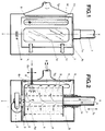
- The device is described below with reference to the schematic drawings attached as examples.
- Figure 1 is a side view of the device illustrating the access door;
- Figure 2 is a sectional view according to a plane passing through the axis X-X and a longitudinal slot in which a branch of the mobile duct is mounted, provided with one or more terminal nozzles for the air;
- Figure 3, similar to Figure 2, illustrates a variant relative to the input of the compressed air into the container;
- Figure 4 schematically illustrates a container for the cleaning of a plurality of filters, two, three or more, whose number -n- is variable according to the capacity of the container and of the pneumatic means associated to the plant;
- Figure 5 is an enlarged particular of Figure 4;
- Figure 6, similar to Figures 2 and 3, schematically illustrates, also in axonometric view, a system and the accessories used for cleaning filters having a shape different from the cylindrical shape, particularly flat filters;
- Figure 7 is a plane view of Figure 6;
- Figure 8 is an enlarged particular of a common type of filter for motor vehicles.
- With reference to Figures 1 and 2, 1 indicates a container, in which a
support 2 is mounted revolving, as indicated by the arrow 4a, which can be set into angular motion, in both directions, at variable speed, by means of theshaft 3 of a suitable gearedmotor 4, mounted on the outside of thecasing 1, controlled by commutator-switch 9. Anannular flange 5 is mounted axially opposite to thesupport 2, said flange being fixed to atubular duct 7 slidably mounted, as indicated by thearrow 7a, in acollar 1a, fixed to thecasing 1. Aspring 6, attached to thetube 7, with the interposition of at least one antifriction means 7b, such as a ball bearing, pushes theflange 5 and the filter -F- against the support 2 (Figure 2). - 1f indicates a longitudinal opening defined by juxtaposed rims fitting into a
part 1h in elastically deformable material such as suitably hard rubber or other suitable material; atubular branch 8 for compressed air -P- and provided with at least oneterminal nozzle 8b, passes through said opening; said tubular branch can run, in both directions, through the opening 1f as indicated by thearrow 8a. - 1b indicates a water tight door; 1c indicates opening-closing means for said door; 1d indicates a window protected by a fixed and transparent sheet which allows for inspection of the inside of the
container 1. The container is provided with asuction collector 1g, associated to known means for the separation of the dust from the air. - The device works as described below:
a cylindrical filter -F- to be cleaned is inserted between thesupport 2 and theflange 5, through thedoor 1b; the reaction of thespring 6 blocks the filter -F- in the position as shown in Figure 2. - Compressed air is blown through the
duct 7, which hits, from the inside towards the outside, the filter set into angular movement around the axis X-X by the gearedmotor 4. - Compressed air -P- is blown into the opening 1f with alternate movement through the
duct 8, said air coming out of thenozzle 8b and hitting the outside surface of the filter -F- freeing it from the dust and other impurities. The action of the compressed air -A- combined with the action of the compressed air -P- and with the rotating movement of the filter, cleans the body of the same while the dust is directed to thesuction collector 1g from which, in the direction -B-, it is sent on to the separating plant. Obviously the two air flows -A- and -P- are separately rated in volume and pressure. - The
casing 1 can be advantageously provided with one or more longitudinal and/ortransverse openings 1f, and relative ducts for jets of air in order to accelerate the cleaning cycles of the filters. Theduct 8, withnozzle 8b, can be set into alternate movement both manually and mechanically by means of the gearedmotor 4 or other electric or pneumatic means. - With reference to Figure 3, without altering the working characteristics of the device as described, at the entrance of the
duct 7 anejector 10 is provided said ejector having a nozzle 11 controlled by an electro-valve 12 connected to atank 13 which, in turn, is connected, in 14, to a suitable air compressor. The electro-valve 12 can be controlled either cyclicly or manually in order to input temporary jets of compressed air which, added to the compressed air already flowing into the filter -F-, generate pneumatic thrusts which can free the filter -F- from all the impurities held in its alveoli. - In Figure 4, the container indicated by 15 is provided with a duct for the
compressed air 7 from which a plurality ofbranches 16 derive each one being provided with an intercepting valve or electro-valve 17; each duct derived is associated to a support for a filter -F- of the type described and illustrated in Figures 2 and 3. Each support can be set into angular motion by a gearedmotor 4 or by transmission means activated by a single motor. Thecontainer 15 can, furthermore, advantageously be provided withsupplementary entrances - As illustrated in Figure 5, to adapt the
opposite supports branches - With reference to Figure 6, for cleaning the filters -F-, which are not cylindrical but substantially flat, said filters are inserted between the
supports grill 20 placed on one face of the filter while ahollow sector 21 is anyway temporarily fixed to thegrill 20, for example by means ofhooks 22. In these conditions a chamber -C- is formed, close to the filter, defined by thegrill 20, by thepart 21, whose transverse profile can anyway be different from that illustrated as an example, and by thesupport planes spring 6 blocks the filter into place. For the correct positioning of the filter - orientated on a parallel plane to the axis X-X - and of theparts support 2 or on the surfaces of both thesupports air 23, disposed in front of thegrill 20, remove the dust from the facing surface. The opening 11a and the elasticallydeformable part 8a are orientated in a transverse direction with respect to the axis X-X. Thegrill 20 holds the filter and prevents deformation caused by the jet of compressed air arriving from theduct 7. Slow angular alternate motion is advantagiously applied to thesupport 2, for the width of an angle - - so as to allow the jet(s) of air emitted from thenozzles 25 to gradually hit all the folded surface of the filter, particularly the single side surfaces -F2-, Figure 8, of the different folds; the branch of theduct 24 can be oscillated into thetransverse opening 11a of thecasing 1 and can be set into alternate motion either manually or mechanically. - The device described can advantageously be provided with means for separating the dust and can constitute an autonomous and compact unit.
- It is evident from the above that it is advantageous to fit batteries with suitable cells each containing a cleaning device programmed for a specific series of filters; the various cells connected to a single compressed air plant, the whole being able to clean filters of different shapes and sizes, regenerating them. Such apparatus, which can be placed for example in motor vehicle service stations are suitable for the quick cleaning of any type of air filter, mounted on the engine of any motor vehicle, said filter being reactivated at considerably low cost.
Claims (7)
- Pneumatic device for cleaning air filters for industrial use and particularly for filters mounted on endothermic engines and on motor vehicles in general, characterised by the fact that it comprises: a casing (1) ccnnected to a duct (7) for the compressed air; at least one water tight door (1d) for access to the casing; at least one inside support to said casing made up of flat, parallel and coaxial parts (2, 5), one of said parts (5) constituted by an annular flange fixed to the duct (7); means for setting into angular motion the said support (2, 5); one or more mobile nozzles (8b) for compressed air; a discharge duct in depression (1g); auxiliary electromechanical means.
- Pneumatic device according to Claim 1, for cleaning a single cylindrical filter (F) (Figures 1, 2), characterised by the fact that one of the plates (2) is connected to kinematic means (4) while the opposite plate (5) is an annular flange connected to the duct (7) coaxxial to the filter (F); furthermore characterised by the fact that the nozzle (8b) which ejects compressed air onto the outside surface of the filter to be cleaned is carried by a branch of the duct (8) mounted slidable in an opening (1h) made in a strip of elastic material (1f); said opening being parallel to the axis X-X of rotation of the filter (F).
- Device according to Claim 1, and according to a variant (Figure 3), characterised by the fact that an ejector for compressed air (10, 11) is inserted in the duct (7) controlled by an electro-valve (12) in order to input jets of air generating pneumatic thrusts periodically into the cleaning device so as to improve the cleaning of the filters.
- Device according to Claim 1, and according to a second variant (Figure 4) characterised in that a number -n- of supports for filter (F) are mounted in a casing (15) of a suitable size, subject to compressed air fed through a duct (7) provided with -n- tubular branches (16) each one provided with an intercepting valve (17); said branches being telescopic (16, 16a - Figure 5), one for each support.
- Device according to Claim 1, and according to another variant (Figures 6, 7, 8) for flat shaped filters (F1) characterised by the fact that the filter is inserted between the parts (2, 5) of the corresponding support together with a front grill (20) and to a boxed body (21), linked to the said grill and defining a chamber -C- into which the compressed air arrives from the duct (7) while nozzles (25), derived from a duct (24), slidable in a transverse opening (11a) of the casing (1), eject compressed air against the filter through the grill (20).
- Device according to Claims 1 and 5, in which, when the cleaning cycle refers to flat filters (F1, Figures 6, 7, 6) the support (2, 5) and/or the nozzle equipment (20) are set into angular alternate motion so as to hit the relative surface with compressed air and remove any foreign body also from the sides (F2) of the folds of the filter.
- Device for cleaning air filters, particularly for filters mounted on motor vehcile engines, characterised by the fact that a number -n- of devices housed in single cells made up a single battery of a plurality of devices able to clean filters of different shapes and sizes; all the cells being fed singularly or together, by a single source of compressed air.
Applications Claiming Priority (2)
| Application Number | Priority Date | Filing Date | Title |
|---|---|---|---|
| ITBZ910010 | 1991-03-29 | ||
| ITBZ910010A IT1249087B (en) | 1991-03-29 | 1991-03-29 | AIR FILTER CLEANING DEVICE |
Publications (2)
| Publication Number | Publication Date |
|---|---|
| EP0506171A1 true EP0506171A1 (en) | 1992-09-30 |
| EP0506171B1 EP0506171B1 (en) | 1998-01-07 |
Family
ID=11346506
Family Applications (1)
| Application Number | Title | Priority Date | Filing Date |
|---|---|---|---|
| EP92200750A Expired - Lifetime EP0506171B1 (en) | 1991-03-29 | 1992-03-17 | Pneumatic device for cleaning air filters |
Country Status (15)
| Country | Link |
|---|---|
| US (1) | US5305493A (en) |
| EP (1) | EP0506171B1 (en) |
| JP (1) | JPH0674112A (en) |
| KR (1) | KR0138504B1 (en) |
| CN (1) | CN1026760C (en) |
| AR (1) | AR246189A1 (en) |
| AT (1) | ATE161748T1 (en) |
| AU (1) | AU658865B2 (en) |
| BR (1) | BR9201191A (en) |
| CA (1) | CA2063881A1 (en) |
| DE (1) | DE69223832T2 (en) |
| FI (1) | FI97698C (en) |
| IT (1) | IT1249087B (en) |
| NO (1) | NO175355C (en) |
| YU (1) | YU48119B (en) |
Cited By (9)
| Publication number | Priority date | Publication date | Assignee | Title |
|---|---|---|---|---|
| FR2717407A1 (en) * | 1994-03-17 | 1995-09-22 | Qual Id 38 | Device for dusting large flexible tanks ("BIG-BAGS"). |
| RU2145676C1 (en) * | 1998-03-13 | 2000-02-20 | Воронежский государственный аграрный университет им.К.Д.Глинки | Air cleaner for internal combustion engine |
| EP1186354A3 (en) * | 2000-09-12 | 2002-08-14 | Fraunhofer-Gesellschaft zur Förderung der angewandten Forschung e.V. | Method and device for cleaning used bulk bags or the like |
| EP1186356A3 (en) * | 2000-09-07 | 2003-08-13 | Yugen Kaisha Showa Kogyosho | Cleaning apparatus |
| CN101994614A (en) * | 2010-11-11 | 2011-03-30 | 福州市公共交通集团有限责任公司 | Dust removal device for air filter cartridge |
| WO2014133474A3 (en) * | 2013-02-26 | 2014-11-13 | Adeba Mühendi̇sli̇k, Danişmanlik, Halkla İli̇şki̇ler, İnşaat Ve Ti̇caret A.Ş. | Telescopic cleaning system for exhaust air filters |
| CN104451987A (en) * | 2013-09-18 | 2015-03-25 | 立达英格尔施塔特有限公司 | Method for cleaning a filter in a line and line comprising a suction system |
| CN107246337A (en) * | 2017-08-20 | 2017-10-13 | 芜湖乐普汽车科技有限公司 | A kind of air cleaner |
| WO2020225407A1 (en) * | 2019-05-08 | 2020-11-12 | Ecoclean Gmbh | Cleaning apparatus |
Families Citing this family (48)
| Publication number | Priority date | Publication date | Assignee | Title |
|---|---|---|---|---|
| US5562251A (en) * | 1993-09-03 | 1996-10-08 | Goyen Controls & Co. Pty. Limited | Gas nozzle for bag house cleaning systems |
| US5431823A (en) * | 1994-08-18 | 1995-07-11 | Electric Fuel(E.F.L.) Ltd. | Process for supporting and cleaning a mesh anode bag |
| US5915439A (en) * | 1997-06-23 | 1999-06-29 | Zaiser; Harold W. | Apparatus for cleaning cylindrical air filters |
| KR100437357B1 (en) * | 1997-07-03 | 2004-07-16 | 에스케이 주식회사 | Automatic hammering system |
| US6216710B1 (en) * | 1999-02-05 | 2001-04-17 | Caterpillar Inc. | Method and apparatus for removing quench oil from a permeable metal part |
| US6511852B1 (en) * | 1999-06-18 | 2003-01-28 | International Flavors & Fragrances Inc. | Apparatus for collecting a volatile composition of matter releasably bonded to a pliable porous substrate and process for using said apparatus |
| KR20020009227A (en) * | 2000-07-25 | 2002-02-01 | 변상철 | Device for cleaning exhaust-gas of combustion chamber burning synthetic fiber |
| KR20040026491A (en) * | 2002-09-25 | 2004-03-31 | 현대자동차주식회사 | System for automatically sweeping filter element of air cleaner for vehicle |
| US6736722B1 (en) | 2002-12-04 | 2004-05-18 | Deere & Company | Unloader tube cleaning system for harvesting apparatus |
| US6835130B2 (en) | 2002-12-04 | 2004-12-28 | Deere & Co. | Grain compartment cleanout arrangement |
| JP2005040744A (en) * | 2003-07-24 | 2005-02-17 | Thai Toyo Denso Co Ltd | Air blow cleaning device |
| CN101320677B (en) * | 2003-08-25 | 2012-02-01 | 东京毅力科创株式会社 | Method for cleaning elements in vacuum chamber and apparatus for processing substrates |
| US20060042036A1 (en) * | 2004-08-31 | 2006-03-02 | Rovcal, Inc. | Electric shaver and cleaning system therefor |
| CN100360788C (en) * | 2004-11-17 | 2008-01-09 | 刘夫东 | Method for realizing replacement-proof air filter screen for engines and apparatus therefor |
| US8951321B2 (en) | 2005-03-31 | 2015-02-10 | Donaldson Company, Inc. | Pulse jet air cleaner components; features; assemblies; and, methods |
| WO2006133321A2 (en) * | 2005-06-03 | 2006-12-14 | Arnold Mark T | Prewash dish cleaning device |
| US7395650B2 (en) * | 2006-02-16 | 2008-07-08 | Deere & Company | Combine auger trough cleanout door |
| KR101439575B1 (en) * | 2007-03-08 | 2014-09-11 | 닛신 엔지니어링 가부시키가이샤 | Nozzle, dry cleaner, dry cleaner system |
| US20090320620A1 (en) * | 2008-06-27 | 2009-12-31 | Nuctech Company Limited | Door-type passenger security inspection apparatus and method for detecting contraband articles such as narcotic drugs, explosives |
| US8317890B2 (en) | 2008-08-29 | 2012-11-27 | Donaldson Company, Inc. | Filter assembly; components therefor; and, methods |
| JP2010095267A (en) * | 2008-10-15 | 2010-04-30 | Trinc:Kk | Dust remover for container |
| US9221083B2 (en) * | 2011-05-27 | 2015-12-29 | Robert T. Rife | Air filter reconditioning apparatus and method |
| CN102441544A (en) * | 2011-09-08 | 2012-05-09 | 索润保 | Device for washing air filter core of car |
| US9605628B2 (en) | 2014-03-06 | 2017-03-28 | Benjamin Lee Woodward | Non-invasive pneumatic filter cleaning apparatus and method |
| CN104275056A (en) * | 2014-09-02 | 2015-01-14 | 广西柳工机械股份有限公司 | Air filter maintenance device |
| CN104265519B (en) * | 2014-09-26 | 2017-01-25 | 长城汽车股份有限公司 | air filter of engine |
| CN105126482A (en) * | 2015-09-25 | 2015-12-09 | 天津天美环保科技有限公司 | Dust collecting bag cleaner |
| CN105863902B (en) * | 2016-06-06 | 2019-01-01 | 衢州丰帆科技有限公司 | A kind of vehicle air cleaner dust-extraction unit |
| CN106089513B (en) * | 2016-06-20 | 2018-08-21 | 山西人来人往企业管理咨询有限公司 | One kind exempting from maintenance type automatically cleaning air filtering core assembly apparatus |
| KR200484311Y1 (en) * | 2016-10-12 | 2017-08-23 | 주식회사 디에이치테크 | Double speed control valve of air injection apparatus for cleaning filter in vacuum cleaner |
| CN108079700B (en) * | 2016-11-22 | 2021-11-19 | 上海宝钢工业技术服务有限公司 | Cleaning device for filter element of air filter |
| RU2716807C2 (en) * | 2017-07-10 | 2020-03-16 | Ледовский Дмитрий Александрович | Device for cleaning indoor air from harmful gases, aerosols, combustion products in fire and technogenic accidents |
| KR102074864B1 (en) * | 2018-05-08 | 2020-02-10 | 주식회사 케이엠에프 | Dust remover for fuel filter |
| CN109603314A (en) * | 2018-10-18 | 2019-04-12 | 株洲市超宇实业有限责任公司 | Sand-blasting machine filtration core clears up ring |
| KR102224875B1 (en) * | 2018-12-13 | 2021-03-09 | 주식회사 디엔피코퍼레이션 | Cleaning Method for Dust Collection Filter Used for Laser Drilling |
| CN110523692A (en) * | 2019-09-23 | 2019-12-03 | 红云红河烟草(集团)有限责任公司 | Cigarette making machine brush dehydration device |
| KR102360579B1 (en) * | 2019-10-04 | 2022-02-09 | 전혁 | A filter for air cleaner |
| KR102299620B1 (en) * | 2019-11-20 | 2021-09-10 | 주식회사 위니아딤채 | Filter rotary type air cleaner |
| CN110882581A (en) * | 2019-11-25 | 2020-03-17 | 河北法远家具有限公司 | A filter cartridge cleaning device |
| CN110761924B (en) * | 2019-11-28 | 2025-01-24 | 王纲 | Air filter cleaning machine |
| CN111151512B (en) * | 2020-02-18 | 2025-01-14 | 长江南京航道工程局 | Blowing and cleaning device and automatic filter cleaning equipment having the same |
| CN111396220A (en) * | 2020-03-03 | 2020-07-10 | 浙江邗越智能科技有限公司 | A dustable self-cleaning air filter |
| CN112459932A (en) * | 2020-11-25 | 2021-03-09 | 蚌埠金威滤清器有限公司 | Efficient air cleaner assembly |
| CN112664484B (en) * | 2020-12-21 | 2022-05-24 | 云南云铝海鑫铝业有限公司 | Hot-blast self-loopa of centrifugal oilless air compressor machine prevents air inlet filter core and blocks up system that freezes |
| CN113135171B (en) * | 2021-04-12 | 2022-09-09 | 安徽金路车辆制造有限公司 | Air storage cylinder for truck and processing method thereof |
| CN113399134A (en) * | 2021-07-13 | 2021-09-17 | 中国北方车辆研究所 | Parallel dust extraction matching structure of cyclone tube separator and method for improving dust extraction reliability |
| KR102536404B1 (en) * | 2022-06-20 | 2023-05-26 | 신승배 | Filter cleaner |
| US12023615B1 (en) | 2023-11-10 | 2024-07-02 | Filter Preaux, LLC | Cartridge filter cleaning system and method |
Citations (2)
| Publication number | Priority date | Publication date | Assignee | Title |
|---|---|---|---|---|
| EP0078678A1 (en) * | 1981-10-30 | 1983-05-11 | Colortronic Co., Ltd. | Method and apparatus for cleaning filters |
| US4585019A (en) * | 1984-06-08 | 1986-04-29 | Jacobson Dwight W | Heavy duty air filter reconditioning system |
Family Cites Families (9)
| Publication number | Priority date | Publication date | Assignee | Title |
|---|---|---|---|---|
| US2242901A (en) * | 1940-03-16 | 1941-05-20 | Birch Thomas Henry | Strainer cleaning device |
| US3538926A (en) * | 1967-11-28 | 1970-11-10 | Denver Wood Products Co | Washer-dryer for automotive type air filters |
| US3733639A (en) * | 1970-10-19 | 1973-05-22 | M Timian | Renovator |
| US3765051A (en) * | 1971-11-12 | 1973-10-16 | A Nu Inc | Apparatus for cleaning filter elements or the like |
| US3936902A (en) * | 1974-07-11 | 1976-02-10 | The United States Government As Represented By The Secretary Of The Army | Automatic cleaning apparatus for fluid filters |
| US3978547A (en) * | 1975-12-22 | 1976-09-07 | Lawson Las F | Brake housing cleaner |
| DE2936779A1 (en) * | 1979-09-12 | 1981-04-02 | Fischer, Friedrich W., 7500 Karlsruhe | Suction hood for cleaning large brake systems - has compressed air blow lance and inner rotary blast system for also clearing inspection window |
| US4808234A (en) * | 1984-08-30 | 1989-02-28 | Mcwinn Filter Services Ltd. | Cleaner assembly for air filters |
| US4670062A (en) * | 1985-09-09 | 1987-06-02 | Lester James E | Brake drum cleaner |
-
1991
- 1991-03-29 IT ITBZ910010A patent/IT1249087B/en active IP Right Grant
-
1992
- 1992-03-12 NO NO920973A patent/NO175355C/en unknown
- 1992-03-17 AT AT92200750T patent/ATE161748T1/en not_active IP Right Cessation
- 1992-03-17 EP EP92200750A patent/EP0506171B1/en not_active Expired - Lifetime
- 1992-03-17 DE DE69223832T patent/DE69223832T2/en not_active Expired - Fee Related
- 1992-03-20 AU AU13091/92A patent/AU658865B2/en not_active Ceased
- 1992-03-23 YU YU29392A patent/YU48119B/en unknown
- 1992-03-24 CA CA002063881A patent/CA2063881A1/en not_active Abandoned
- 1992-03-25 FI FI921297A patent/FI97698C/en active
- 1992-03-26 JP JP4068139A patent/JPH0674112A/en not_active Withdrawn
- 1992-03-27 AR AR92322031A patent/AR246189A1/en active
- 1992-03-27 KR KR1019920005083A patent/KR0138504B1/en not_active Expired - Fee Related
- 1992-03-27 US US07/858,772 patent/US5305493A/en not_active Expired - Fee Related
- 1992-03-27 BR BR929201191A patent/BR9201191A/en not_active Application Discontinuation
- 1992-03-28 CN CN92102023A patent/CN1026760C/en not_active Expired - Fee Related
Patent Citations (2)
| Publication number | Priority date | Publication date | Assignee | Title |
|---|---|---|---|---|
| EP0078678A1 (en) * | 1981-10-30 | 1983-05-11 | Colortronic Co., Ltd. | Method and apparatus for cleaning filters |
| US4585019A (en) * | 1984-06-08 | 1986-04-29 | Jacobson Dwight W | Heavy duty air filter reconditioning system |
Cited By (12)
| Publication number | Priority date | Publication date | Assignee | Title |
|---|---|---|---|---|
| FR2717407A1 (en) * | 1994-03-17 | 1995-09-22 | Qual Id 38 | Device for dusting large flexible tanks ("BIG-BAGS"). |
| RU2145676C1 (en) * | 1998-03-13 | 2000-02-20 | Воронежский государственный аграрный университет им.К.Д.Глинки | Air cleaner for internal combustion engine |
| EP1186356A3 (en) * | 2000-09-07 | 2003-08-13 | Yugen Kaisha Showa Kogyosho | Cleaning apparatus |
| EP1186354A3 (en) * | 2000-09-12 | 2002-08-14 | Fraunhofer-Gesellschaft zur Förderung der angewandten Forschung e.V. | Method and device for cleaning used bulk bags or the like |
| CN101994614A (en) * | 2010-11-11 | 2011-03-30 | 福州市公共交通集团有限责任公司 | Dust removal device for air filter cartridge |
| CN101994614B (en) * | 2010-11-11 | 2013-01-16 | 福州市公共交通集团有限责任公司 | Dust removal device for air filter cartridge |
| WO2014133474A3 (en) * | 2013-02-26 | 2014-11-13 | Adeba Mühendi̇sli̇k, Danişmanlik, Halkla İli̇şki̇ler, İnşaat Ve Ti̇caret A.Ş. | Telescopic cleaning system for exhaust air filters |
| CN104451987A (en) * | 2013-09-18 | 2015-03-25 | 立达英格尔施塔特有限公司 | Method for cleaning a filter in a line and line comprising a suction system |
| CN104451987B (en) * | 2013-09-18 | 2019-10-25 | 立达英格尔施塔特有限公司 | Method for cleaning filters on road sections and road sections with suction system |
| CN107246337A (en) * | 2017-08-20 | 2017-10-13 | 芜湖乐普汽车科技有限公司 | A kind of air cleaner |
| WO2020225407A1 (en) * | 2019-05-08 | 2020-11-12 | Ecoclean Gmbh | Cleaning apparatus |
| US12179240B2 (en) | 2019-05-08 | 2024-12-31 | Ecoclean Gmbh | Cleaning apparatus |
Also Published As
| Publication number | Publication date |
|---|---|
| EP0506171B1 (en) | 1998-01-07 |
| US5305493A (en) | 1994-04-26 |
| DE69223832D1 (en) | 1998-02-12 |
| YU48119B (en) | 1997-03-07 |
| ITBZ910010A0 (en) | 1991-03-29 |
| NO175355B (en) | 1994-06-27 |
| FI97698C (en) | 1997-02-10 |
| KR920017697A (en) | 1992-10-21 |
| FI921297A7 (en) | 1992-09-30 |
| FI921297A0 (en) | 1992-03-25 |
| CA2063881A1 (en) | 1992-09-30 |
| BR9201191A (en) | 1992-11-24 |
| KR0138504B1 (en) | 1998-04-27 |
| AU1309192A (en) | 1992-10-01 |
| CN1065509A (en) | 1992-10-21 |
| AU658865B2 (en) | 1995-05-04 |
| ATE161748T1 (en) | 1998-01-15 |
| IT1249087B (en) | 1995-02-11 |
| ITBZ910010A1 (en) | 1992-09-29 |
| CN1026760C (en) | 1994-11-30 |
| FI97698B (en) | 1996-10-31 |
| YU29392A (en) | 1994-06-10 |
| NO175355C (en) | 1994-10-05 |
| DE69223832T2 (en) | 1998-07-09 |
| AR246189A1 (en) | 1994-07-29 |
| NO920973L (en) | 1992-09-30 |
| NO920973D0 (en) | 1992-03-12 |
| JPH0674112A (en) | 1994-03-15 |
Similar Documents
| Publication | Publication Date | Title |
|---|---|---|
| US5305493A (en) | Pneumatic device for cleaning air filters | |
| AU613754B2 (en) | Air filtering apparatus | |
| KR101549242B1 (en) | Dedusting device for bag filter used in dust collector | |
| JPH10137528A (en) | Cyclone dust collector | |
| GB1501066A (en) | Cleaning vehicles | |
| EP0793988A2 (en) | Filter for a motorized sweeper and related machine | |
| GB2270334A (en) | Pneumatic refuse collection and filter apparatus for a roadsweeper | |
| GB2199267A (en) | A gas separating apparatus | |
| CN112870867A (en) | Device for efficiently filtering dust particles | |
| CN119896915A (en) | A bag dust collector for gypsum powder production line | |
| CN117619070B (en) | Integrated composite filter cartridge dust remover | |
| CN209976599U (en) | DPF cleaning machine | |
| CN216726235U (en) | Telescopic bag-type dust collector | |
| CN209752438U (en) | Combined pulse filter cartridge dust remover | |
| CN118384612B (en) | Solid waste incineration smoke treatment equipment | |
| CN223170548U (en) | Self-ash-cleaning mechanism of bag type dust collector | |
| CN2190521Y (en) | Rhombus bag type dust collecter | |
| CN112426822A (en) | High-efficiency dust collector | |
| CN119951235A (en) | A dust collector with self-cleaning function | |
| CN221412567U (en) | AC foaming agent production workshop dust remover | |
| CN223249971U (en) | Automatic carry dust collecting equipment | |
| CN219764783U (en) | Anti-blocking dust removal filter | |
| CN113911009B (en) | A vehicle-mounted air purifier | |
| CN213132390U (en) | Vibrating exhaust gas purification equipment | |
| CN223234600U (en) | A rail vehicle side blowing and dust collecting device |
Legal Events
| Date | Code | Title | Description |
|---|---|---|---|
| PUAI | Public reference made under article 153(3) epc to a published international application that has entered the european phase |
Free format text: ORIGINAL CODE: 0009012 |
|
| AK | Designated contracting states |
Kind code of ref document: A1 Designated state(s): AT BE CH DE DK ES FR GB GR IT LI LU MC NL PT SE |
|
| 17P | Request for examination filed |
Effective date: 19921216 |
|
| 17Q | First examination report despatched |
Effective date: 19941125 |
|
| RAP3 | Party data changed (applicant data changed or rights of an application transferred) |
Owner name: COFISE S.P.A. |
|
| GRAG | Despatch of communication of intention to grant |
Free format text: ORIGINAL CODE: EPIDOS AGRA |
|
| GRAG | Despatch of communication of intention to grant |
Free format text: ORIGINAL CODE: EPIDOS AGRA |
|
| GRAH | Despatch of communication of intention to grant a patent |
Free format text: ORIGINAL CODE: EPIDOS IGRA |
|
| GRAH | Despatch of communication of intention to grant a patent |
Free format text: ORIGINAL CODE: EPIDOS IGRA |
|
| GRAA | (expected) grant |
Free format text: ORIGINAL CODE: 0009210 |
|
| AK | Designated contracting states |
Kind code of ref document: B1 Designated state(s): AT BE CH DE DK ES FR GB GR IT LI LU MC NL PT SE |
|
| PG25 | Lapsed in a contracting state [announced via postgrant information from national office to epo] |
Ref country code: GR Free format text: LAPSE BECAUSE OF FAILURE TO SUBMIT A TRANSLATION OF THE DESCRIPTION OR TO PAY THE FEE WITHIN THE PRESCRIBED TIME-LIMIT Effective date: 19980107 Ref country code: ES Free format text: THE PATENT HAS BEEN ANNULLED BY A DECISION OF A NATIONAL AUTHORITY Effective date: 19980107 Ref country code: LI Free format text: LAPSE BECAUSE OF FAILURE TO SUBMIT A TRANSLATION OF THE DESCRIPTION OR TO PAY THE FEE WITHIN THE PRESCRIBED TIME-LIMIT Effective date: 19980107 Ref country code: AT Free format text: LAPSE BECAUSE OF FAILURE TO SUBMIT A TRANSLATION OF THE DESCRIPTION OR TO PAY THE FEE WITHIN THE PRESCRIBED TIME-LIMIT Effective date: 19980107 Ref country code: BE Free format text: LAPSE BECAUSE OF FAILURE TO SUBMIT A TRANSLATION OF THE DESCRIPTION OR TO PAY THE FEE WITHIN THE PRESCRIBED TIME-LIMIT Effective date: 19980107 Ref country code: CH Free format text: LAPSE BECAUSE OF FAILURE TO SUBMIT A TRANSLATION OF THE DESCRIPTION OR TO PAY THE FEE WITHIN THE PRESCRIBED TIME-LIMIT Effective date: 19980107 Ref country code: NL Free format text: LAPSE BECAUSE OF FAILURE TO SUBMIT A TRANSLATION OF THE DESCRIPTION OR TO PAY THE FEE WITHIN THE PRESCRIBED TIME-LIMIT Effective date: 19980107 |
|
| REF | Corresponds to: |
Ref document number: 161748 Country of ref document: AT Date of ref document: 19980115 Kind code of ref document: T |
|
| REG | Reference to a national code |
Ref country code: CH Ref legal event code: EP |
|
| REF | Corresponds to: |
Ref document number: 69223832 Country of ref document: DE Date of ref document: 19980212 |
|
| PG25 | Lapsed in a contracting state [announced via postgrant information from national office to epo] |
Ref country code: LU Free format text: LAPSE BECAUSE OF NON-PAYMENT OF DUE FEES Effective date: 19980317 |
|
| ITF | It: translation for a ep patent filed | ||
| PG25 | Lapsed in a contracting state [announced via postgrant information from national office to epo] |
Ref country code: GB Free format text: LAPSE BECAUSE OF NON-PAYMENT OF DUE FEES Effective date: 19980407 Ref country code: PT Free format text: LAPSE BECAUSE OF FAILURE TO SUBMIT A TRANSLATION OF THE DESCRIPTION OR TO PAY THE FEE WITHIN THE PRESCRIBED TIME-LIMIT Effective date: 19980407 Ref country code: SE Free format text: LAPSE BECAUSE OF FAILURE TO SUBMIT A TRANSLATION OF THE DESCRIPTION OR TO PAY THE FEE WITHIN THE PRESCRIBED TIME-LIMIT Effective date: 19980407 Ref country code: DK Free format text: LAPSE BECAUSE OF FAILURE TO SUBMIT A TRANSLATION OF THE DESCRIPTION OR TO PAY THE FEE WITHIN THE PRESCRIBED TIME-LIMIT Effective date: 19980407 |
|
| ET | Fr: translation filed | ||
| NLV1 | Nl: lapsed or annulled due to failure to fulfill the requirements of art. 29p and 29m of the patents act | ||
| REG | Reference to a national code |
Ref country code: CH Ref legal event code: PL |
|
| PG25 | Lapsed in a contracting state [announced via postgrant information from national office to epo] |
Ref country code: MC Free format text: LAPSE BECAUSE OF NON-PAYMENT OF DUE FEES Effective date: 19980930 |
|
| PLBE | No opposition filed within time limit |
Free format text: ORIGINAL CODE: 0009261 |
|
| STAA | Information on the status of an ep patent application or granted ep patent |
Free format text: STATUS: NO OPPOSITION FILED WITHIN TIME LIMIT |
|
| GBPC | Gb: european patent ceased through non-payment of renewal fee |
Effective date: 19980407 |
|
| 26N | No opposition filed | ||
| PGFP | Annual fee paid to national office [announced via postgrant information from national office to epo] |
Ref country code: FR Payment date: 20060308 Year of fee payment: 15 |
|
| PGFP | Annual fee paid to national office [announced via postgrant information from national office to epo] |
Ref country code: DE Payment date: 20060309 Year of fee payment: 15 |
|
| REG | Reference to a national code |
Ref country code: FR Ref legal event code: ST Effective date: 20071130 |
|
| PG25 | Lapsed in a contracting state [announced via postgrant information from national office to epo] |
Ref country code: DE Free format text: LAPSE BECAUSE OF NON-PAYMENT OF DUE FEES Effective date: 20071002 |
|
| PG25 | Lapsed in a contracting state [announced via postgrant information from national office to epo] |
Ref country code: FR Free format text: LAPSE BECAUSE OF NON-PAYMENT OF DUE FEES Effective date: 20070402 |
|
| PG25 | Lapsed in a contracting state [announced via postgrant information from national office to epo] |
Ref country code: IT Free format text: LAPSE BECAUSE OF NON-PAYMENT OF DUE FEES Effective date: 20090317 |
|
| PGRI | Patent reinstated in contracting state [announced from national office to epo] |
Ref country code: IT Effective date: 20110616 |
|
| PGFP | Annual fee paid to national office [announced via postgrant information from national office to epo] |
Ref country code: IT Payment date: 20110921 Year of fee payment: 20 |