EP0509229A2 - Dispositif de commande pour un brûleur de gaz avec un ventilateur pour l'alimentation d'air de combustion - Google Patents
Dispositif de commande pour un brûleur de gaz avec un ventilateur pour l'alimentation d'air de combustion Download PDFInfo
- Publication number
- EP0509229A2 EP0509229A2 EP92104047A EP92104047A EP0509229A2 EP 0509229 A2 EP0509229 A2 EP 0509229A2 EP 92104047 A EP92104047 A EP 92104047A EP 92104047 A EP92104047 A EP 92104047A EP 0509229 A2 EP0509229 A2 EP 0509229A2
- Authority
- EP
- European Patent Office
- Prior art keywords
- control
- pressure
- control line
- line
- combustion air
- Prior art date
- Legal status (The legal status is an assumption and is not a legal conclusion. Google has not performed a legal analysis and makes no representation as to the accuracy of the status listed.)
- Granted
Links
Images
Classifications
-
- F—MECHANICAL ENGINEERING; LIGHTING; HEATING; WEAPONS; BLASTING
- F23—COMBUSTION APPARATUS; COMBUSTION PROCESSES
- F23N—REGULATING OR CONTROLLING COMBUSTION
- F23N5/00—Systems for controlling combustion
- F23N5/18—Systems for controlling combustion using detectors sensitive to rate of flow of air or fuel
- F23N5/188—Systems for controlling combustion using detectors sensitive to rate of flow of air or fuel using mechanical means
-
- F—MECHANICAL ENGINEERING; LIGHTING; HEATING; WEAPONS; BLASTING
- F23—COMBUSTION APPARATUS; COMBUSTION PROCESSES
- F23N—REGULATING OR CONTROLLING COMBUSTION
- F23N1/00—Regulating fuel supply
- F23N1/02—Regulating fuel supply conjointly with air supply
- F23N1/022—Regulating fuel supply conjointly with air supply using electronic means
-
- F—MECHANICAL ENGINEERING; LIGHTING; HEATING; WEAPONS; BLASTING
- F23—COMBUSTION APPARATUS; COMBUSTION PROCESSES
- F23N—REGULATING OR CONTROLLING COMBUSTION
- F23N2225/00—Measuring
- F23N2225/04—Measuring pressure
- F23N2225/06—Measuring pressure for determining flow
-
- F—MECHANICAL ENGINEERING; LIGHTING; HEATING; WEAPONS; BLASTING
- F23—COMBUSTION APPARATUS; COMBUSTION PROCESSES
- F23N—REGULATING OR CONTROLLING COMBUSTION
- F23N2233/00—Ventilators
- F23N2233/06—Ventilators at the air intake
- F23N2233/08—Ventilators at the air intake with variable speed
-
- F—MECHANICAL ENGINEERING; LIGHTING; HEATING; WEAPONS; BLASTING
- F23—COMBUSTION APPARATUS; COMBUSTION PROCESSES
- F23N—REGULATING OR CONTROLLING COMBUSTION
- F23N2235/00—Valves, nozzles or pumps
- F23N2235/12—Fuel valves
- F23N2235/18—Groups of two or more valves
Definitions
- the invention relates to a control device for gas burners with a fan for supplying the combustion air according to the preamble of the main claim.
- control devices of this type which are provided with a gas pressure regulator, both control lines are guided freely through the air space between the control pressure orifice and the gas pressure regulator, so that the control pressure signal is falsified if one or both control lines become leaky or broken. If the above-mentioned defect occurs in the first control line branching upstream of the control pressure orifice, this is not detrimental to hygienic burner behavior because this reduces the control pressure difference and thus also reduces the gas quantity or gas pressure, which corresponds to safe behavior of the control device (combustion under Excess air).
- the situation is different if the second control line branching downstream of the control pressure orifice leaks or breaks.
- the back pressure prevailing in the downstream gas-air mixing section is no longer present as a reference pressure at the control pressure orifice, but the atmospheric pressure, which is lower than the reference pressure is.
- the fuel gas pressure is increased, which leads to a disproportionate fuel gas throughput based on the available amount of combustion air. The result is a lack of air combustion that must be avoided.
- control devices for gas burners with a fan for supplying combustion air are known, in which the fuel gas is already introduced into the intake of combustion air flow upstream of the fan and a control pressure orifice, which influences a pneumatic gas pressure regulator, is also arranged upstream of the fan in the combustion air line.
- the reference pressure which is established downstream of the control pressure orifice is below atmospheric pressure, so that if the control line carrying the reference pressure leaks or breaks, the control pressure difference collapses and the gas pressure regulator closes the fuel gas line.
- the arrangement according to the invention with the characterizing features of the main claim has the advantage that it does not lead to an unsafe condition or to a combustion under air deficiency or to combustion in devices with a blower that only promotes combustion air and a control pressure orifice arranged downstream of the blower if the control lines become leaky or there is a line break. can come to a small position of the gas burner, in which a hygienic combustion is no longer guaranteed. If the second control line carrying the reference pressure breaks in this arrangement, this results in a short circuit between the two control lines, as a result of which the control pressure difference breaks down and the pneumatic actuator reacts in the sense of interrupting the fuel gas supply. If the first control line branched off upstream of the control pressure orifice breaks, the control pressure difference also decreases, which corresponds to a safety-related reaction of the pneumatic actuator.
- the pneumatic actuator is part of a gas pressure regulator in the fuel gas line, the setpoint of which is predetermined by the control pressure orifice in the combustion air line. This results in a pneumatic compound control for the two combustion components, air and gas, which adapts the fuel gas supply to the respective combustion air volume flow controlled by the heat requirement in the sense of optimizing the combustion for each required burner output within a predetermined output range.
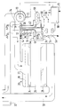
- FIG. 1 An embodiment of the invention is shown in the drawing and explained in more detail in the following description.
- the single figure shows schematically a burner device for a gas-heated water heater, which is provided with a pneumatic compound control for the combustion components.
- the burner device has a fan 10 for supplying combustion air, the speed of which is controlled in accordance with the heat requirement.
- the fan 10 conveys the sucked-in combustion air into a channel 12, into which a gas line 16 carrying the fuel gas opens at the point 14.
- the channel 12 leads into a distribution chamber 18 of a premix burner 20, from which the fuel-air mixture passes through a perforated plate 22, evenly distributed, into the combustion zone 24 of the premix burner 20, which is designed as a ceramic burner block.
- the combustion takes place in a combustion chamber 26, which is closed at the bottom by a heat exchanger 28 for the water to be heated. After the heat exchanger 28, the exhaust gases enter an exhaust duct 30, which leads through a fresh air duct 32 into a chimney or into the open.
- a control pressure orifice 34 is installed in the duct 12 between the blower 10 and the point 14 and specifies a setpoint for a gas pressure regulator 36 in the gas line 16.
- the control pressure orifice 34 derives a control pressure signal in the form of a differential pressure from the air volume flow in the channel 12, which is transmitted to the gas pressure regulator 36 via two control lines 38, 40.
- the first control line 38 branches upstream of the control pressure orifice 34 from the channel 12 and leads into a high pressure chamber 42 of a pneumatic actuator 44 in the gas pressure regulator 36.
- the second control line 40 branches off downstream of the control pressure orifice 34 from the channel 12 and leads into a low pressure chamber 46 of the actuator 44, which is separated from the high pressure chamber 42 by a membrane or the like.
- the second control line 40 is led over its entire length through a prechamber 50 which is permanently connected to the high pressure chamber 42 of the actuator 44.
- the pre-chamber 50 is formed in a tube 52 which concentrically surrounds the second control line 40.
- the first control line 38 opens into the tube 52, which thereby directly forms a section of the first control line 38.
- the fuel gas supply is monitored by the gas pressure regulator 36 by two solenoid valves 54, 56, one of which, 54, is controlled by an additional differential pressure switch 58 via a switch contact 60 in such a way that it only releases the gas line 16 when the air volume flow in the duct 12 exceeds a predetermined minimum value.
- the differential pressure switch 58 is also connected to the channel 12 via two control lines 62, 64 upstream and downstream of the control pressure orifice 34.
- the differential pressure switch 58 has a second switching contact 66, which opens the second solenoid valve 56 via a control unit 68 and activates the ignition of the premix burner when a heat demand signal 70 has caused the control unit 68 to switch on the blower 10 and the pressure difference at the control pressure orifice 34 has a higher, preferably has reached the value corresponding to the nominal power of the device.
- the regulated speed of the fan 10 is reported back to the control unit 68 via a speed sensor 72. If necessary, the measure according to the invention of enveloping the control line 64 by a chamber carrying the pressure in the control line 62 could also be provided for the differential pressure switch 58.
- the pressure difference .DELTA.P St occurs at the control pressure orifice 34, which is transmitted to the gas pressure regulator 36 via the control lines 38, 50.
- this assigns a pressure difference ⁇ P Br between the reference pressure behind the control pressure orifice 34 and the fuel gas pressure to each pressure difference ⁇ P St , that the excess air assumes and maintains a predetermined constant value.
- the control line 40 leaks or breaks, the pressures in the high pressure chamber 42 and the low pressure chamber 46 of the actuator 44 equalize, causing the gas pressure regulator 36 to close the gas line 16. If the heat requirement is below a value corresponding to the lower limit of the predetermined power range or falls below this value, the modulating operation takes the place of the modulating operation, controlled by the differential pressure switch 58 and the solenoid valve 54, of the premix burner 20.
Landscapes
- Engineering & Computer Science (AREA)
- Chemical & Material Sciences (AREA)
- Combustion & Propulsion (AREA)
- Mechanical Engineering (AREA)
- General Engineering & Computer Science (AREA)
- Regulation And Control Of Combustion (AREA)
Applications Claiming Priority (2)
| Application Number | Priority Date | Filing Date | Title |
|---|---|---|---|
| DE4112865A DE4112865A1 (de) | 1991-04-19 | 1991-04-19 | Steuer- bzw. regelvorrichtung fuer gasbrenner mit einem geblaese zum zufuehren der verbrennungsluft |
| DE4112865 | 1991-04-19 |
Publications (3)
| Publication Number | Publication Date |
|---|---|
| EP0509229A2 true EP0509229A2 (fr) | 1992-10-21 |
| EP0509229A3 EP0509229A3 (en) | 1993-01-13 |
| EP0509229B1 EP0509229B1 (fr) | 1996-02-07 |
Family
ID=6429968
Family Applications (1)
| Application Number | Title | Priority Date | Filing Date |
|---|---|---|---|
| EP92104047A Expired - Lifetime EP0509229B1 (fr) | 1991-04-19 | 1992-03-10 | Dispositif de commande pour un brûleur de gaz avec un ventilateur pour l'alimentation d'air de combustion |
Country Status (2)
| Country | Link |
|---|---|
| EP (1) | EP0509229B1 (fr) |
| DE (2) | DE4112865A1 (fr) |
Cited By (2)
| Publication number | Priority date | Publication date | Assignee | Title |
|---|---|---|---|---|
| EP1030108A1 (fr) * | 1999-02-19 | 2000-08-23 | Robert Bosch Gmbh | Brûleur à gaz et procédé de fonctionnement d'un brûleur à gaz |
| EP2292976A3 (fr) * | 2009-09-02 | 2012-11-21 | LOI Thermprocess GmbH | Dispositif de chauffage par rayonnement |
Families Citing this family (1)
| Publication number | Priority date | Publication date | Assignee | Title |
|---|---|---|---|---|
| DE4402036C2 (de) * | 1994-01-25 | 1997-06-12 | Dungs Karl Gmbh & Co | Verbunddruckwächter |
Family Cites Families (2)
| Publication number | Priority date | Publication date | Assignee | Title |
|---|---|---|---|---|
| DE8004780U1 (de) * | 1980-02-22 | 1989-06-15 | G. Kromschröder AG, 4500 Osnabrück | Regelvorrichtung für Gasbrenner |
| US4706881A (en) * | 1985-11-26 | 1987-11-17 | Carrier Corporation | Self-correcting microprocessor control system and method for a furnace |
-
1991
- 1991-04-19 DE DE4112865A patent/DE4112865A1/de not_active Withdrawn
-
1992
- 1992-03-10 EP EP92104047A patent/EP0509229B1/fr not_active Expired - Lifetime
- 1992-03-10 DE DE59205272T patent/DE59205272D1/de not_active Expired - Fee Related
Cited By (2)
| Publication number | Priority date | Publication date | Assignee | Title |
|---|---|---|---|---|
| EP1030108A1 (fr) * | 1999-02-19 | 2000-08-23 | Robert Bosch Gmbh | Brûleur à gaz et procédé de fonctionnement d'un brûleur à gaz |
| EP2292976A3 (fr) * | 2009-09-02 | 2012-11-21 | LOI Thermprocess GmbH | Dispositif de chauffage par rayonnement |
Also Published As
| Publication number | Publication date |
|---|---|
| EP0509229A3 (en) | 1993-01-13 |
| DE59205272D1 (de) | 1996-03-21 |
| DE4112865A1 (de) | 1992-10-22 |
| EP0509229B1 (fr) | 1996-02-07 |
Similar Documents
| Publication | Publication Date | Title |
|---|---|---|
| EP2014979A2 (fr) | Dispositif de fonctionnement pour un brûleur de surface haute performance et son procédé de fonctionnement | |
| EP3957910A1 (fr) | Procédé et agencement de formation pneumatique d'un mélange dans un brûleur de prémélange | |
| DE19635974A1 (de) | Gas/Luft-Mischsystem für Gasheizgeräte | |
| EP0509229B1 (fr) | Dispositif de commande pour un brûleur de gaz avec un ventilateur pour l'alimentation d'air de combustion | |
| EP0567060A1 (fr) | Procédé pour commander un brûleur à gaz avec un ventilateur | |
| DE1284686B (de) | Vergaser fuer Brennkraftmaschinen | |
| DE19905789B4 (de) | Atmosphärischer Gasbrenner sowie Gasverteilervorrichtung für einen Gasbrenner | |
| EP0866270B1 (fr) | Appareil de chauffage à gaz, notamment un chauffe-eau | |
| DE3105862A1 (de) | Gas-geblaesebrenner | |
| DE19822336C2 (de) | Vorrichtung zum Betreiben eines atmosphärischen, insbesondere vollvormischenden Gasbrenners | |
| DE19906935A1 (de) | Gasbrenner sowie Verfahren zum Betreiben eines Gasbrenners | |
| EP0434599B1 (fr) | Brûleur à gaz prémélangé | |
| DE19750873C2 (de) | Verfahren zur Steuerung eines atomsphärischen Gasbrenners für Heizgeräte, insbesondere Wassererhitzer | |
| DE3005393A1 (de) | Vergaser-vorrichtung | |
| DE19501749A1 (de) | Verfahren und Vorrichtung zum Steuern eines Gas-Gebläsebrenners | |
| DE102009037890B4 (de) | Vorrichtung zum Einstellen eines Ausgangsdrucks eines Brenngasvolumenstromes, Verfahren zum Einstellen eines Ausgangsdrucks sowie Verwendung der Vorrichtung in einer Brenngas-Luft-Mischeinrichtung für ein Verbrennungssystem | |
| EP0036613A1 (fr) | Dispositif de régulation pour un échauffeur à eau ou air à combustion gazeuse pouvant être commandé par un capteur de température | |
| DE2756513A1 (de) | Motorbrennstoffregler | |
| DE19809028A1 (de) | Gasbeheizter Wäschetrockner | |
| DE29808799U1 (de) | Regeleinrichtung für Gasbrenner | |
| DE914728C (de) | Verfahren zur Beheizung von Koksoefen mit Starkgasen schwankenden Heizwertes | |
| AT398622B (de) | Verfahren zur steuerung eines gebläsebrenners | |
| EP0284011A2 (fr) | Brûleur atmosphérique à gaz | |
| EP1116916A1 (fr) | Appareil de chauffage à gaz équipé d'un brûleur de prémélange contrôlé pneumatiquement | |
| DE19750870A1 (de) | Verfahren zur Steuerung eines atmosphärischen Gasbrenners für Heizgeräte, insbesondere Wassererhitzer |
Legal Events
| Date | Code | Title | Description |
|---|---|---|---|
| PUAI | Public reference made under article 153(3) epc to a published international application that has entered the european phase |
Free format text: ORIGINAL CODE: 0009012 |
|
| AK | Designated contracting states |
Kind code of ref document: A2 Designated state(s): DE FR GB IT |
|
| PUAL | Search report despatched |
Free format text: ORIGINAL CODE: 0009013 |
|
| AK | Designated contracting states |
Kind code of ref document: A3 Designated state(s): DE FR GB IT |
|
| 17P | Request for examination filed |
Effective date: 19930607 |
|
| 17Q | First examination report despatched |
Effective date: 19950201 |
|
| GRAA | (expected) grant |
Free format text: ORIGINAL CODE: 0009210 |
|
| AK | Designated contracting states |
Kind code of ref document: B1 Designated state(s): DE FR GB IT |
|
| ET | Fr: translation filed | ||
| REF | Corresponds to: |
Ref document number: 59205272 Country of ref document: DE Date of ref document: 19960321 |
|
| ITF | It: translation for a ep patent filed | ||
| GBT | Gb: translation of ep patent filed (gb section 77(6)(a)/1977) |
Effective date: 19960418 |
|
| PLBE | No opposition filed within time limit |
Free format text: ORIGINAL CODE: 0009261 |
|
| STAA | Information on the status of an ep patent application or granted ep patent |
Free format text: STATUS: NO OPPOSITION FILED WITHIN TIME LIMIT |
|
| 26N | No opposition filed | ||
| REG | Reference to a national code |
Ref country code: GB Ref legal event code: IF02 |
|
| PGFP | Annual fee paid to national office [announced via postgrant information from national office to epo] |
Ref country code: FR Payment date: 20020320 Year of fee payment: 11 |
|
| PGFP | Annual fee paid to national office [announced via postgrant information from national office to epo] |
Ref country code: GB Payment date: 20030227 Year of fee payment: 12 |
|
| PGFP | Annual fee paid to national office [announced via postgrant information from national office to epo] |
Ref country code: DE Payment date: 20030425 Year of fee payment: 12 |
|
| PG25 | Lapsed in a contracting state [announced via postgrant information from national office to epo] |
Ref country code: FR Free format text: LAPSE BECAUSE OF NON-PAYMENT OF DUE FEES Effective date: 20031127 |
|
| REG | Reference to a national code |
Ref country code: FR Ref legal event code: ST |
|
| PG25 | Lapsed in a contracting state [announced via postgrant information from national office to epo] |
Ref country code: GB Free format text: LAPSE BECAUSE OF NON-PAYMENT OF DUE FEES Effective date: 20040310 |
|
| PG25 | Lapsed in a contracting state [announced via postgrant information from national office to epo] |
Ref country code: DE Free format text: LAPSE BECAUSE OF NON-PAYMENT OF DUE FEES Effective date: 20041001 |
|
| GBPC | Gb: european patent ceased through non-payment of renewal fee |
Effective date: 20040310 |
|
| PG25 | Lapsed in a contracting state [announced via postgrant information from national office to epo] |
Ref country code: IT Free format text: LAPSE BECAUSE OF NON-PAYMENT OF DUE FEES Effective date: 20050310 |