EP0509965A1 - A system for the movement of the hands of a clock or watch - Google Patents
A system for the movement of the hands of a clock or watch Download PDFInfo
- Publication number
- EP0509965A1 EP0509965A1 EP92830151A EP92830151A EP0509965A1 EP 0509965 A1 EP0509965 A1 EP 0509965A1 EP 92830151 A EP92830151 A EP 92830151A EP 92830151 A EP92830151 A EP 92830151A EP 0509965 A1 EP0509965 A1 EP 0509965A1
- Authority
- EP
- European Patent Office
- Prior art keywords
- hand
- along
- clock
- watch
- section
- Prior art date
- Legal status (The legal status is an assumption and is not a legal conclusion. Google has not performed a legal analysis and makes no representation as to the accuracy of the status listed.)
- Granted
Links
Images




Classifications
-
- G—PHYSICS
- G04—HOROLOGY
- G04B—MECHANICALLY-DRIVEN CLOCKS OR WATCHES; MECHANICAL PARTS OF CLOCKS OR WATCHES IN GENERAL; TIME PIECES USING THE POSITION OF THE SUN, MOON OR STARS
- G04B19/00—Indicating the time by visual means
- G04B19/06—Dials
- G04B19/08—Geometrical arrangement of the graduations
- G04B19/087—Geometrical arrangement of the graduations with several separate scales
-
- G—PHYSICS
- G04—HOROLOGY
- G04B—MECHANICALLY-DRIVEN CLOCKS OR WATCHES; MECHANICAL PARTS OF CLOCKS OR WATCHES IN GENERAL; TIME PIECES USING THE POSITION OF THE SUN, MOON OR STARS
- G04B45/00—Time pieces of which the indicating means or cases provoke special effects, e.g. aesthetic effects
Definitions
- the present invention relates to a system which causes the hand of a clock or watch to perform a new and original movement differing essentially from that of conventional clocks and watches with so-called “analog" time display.
- a system capable of causing the hand of a clock to move in a linear manner along a straight guide slot which is equidistant from opposite side portions of a scale indicating the time on the dial of said clock, and rotating when said hand reaches the top and bottom of said straight guide slot.
- dial 1 of a clock or watch using a system according to the present invention comprising two distinct and separate scales set side by side, of which a first scale, generally indicated with 2, relating to the hours and marked in part with Roman numerals and the rest with respective dots, and a second scale, generally indicated with 3, relating to the minutes, with numbers, for example, marked every five minutes and the remaining minutes indicated by respective dots.
- the two scales 2 and 3 are externally bordered by respective outlines 4 and 5, having the same shape, made up of two straight, parallel, opposite sections, joined by two substantially semicircular sections, one at the top and one at the bottom.
- dial 1 of this embodiment of the invention scales with indicia relating to hours and minutes have been given, it is also possible to provide on the dial itself, as well as the scales mentioned above, scale for seconds next to that for hours or that for minutes, or alternatively the scale for hours alone.
- each scale 2 and 3 a slot 6 and respectively 7 is made in the dial 1, said slot being of the same length as the straight sections of the outlines 4 and 5, each of said slots having a circular enlargement 10 in correspondence with both of the ends.
- a hand 8, 9 runs, connected to a respective mechanism which will be described below and which causes said hand to move in a linear manner along the respective one of said slots, so as to indicate on its upward stroke the hours and the minutes marked on the left hand straight section, respectively, as seen in figure 1, of the outlines 4, 5, while during its downward stroke it indicates the hours and the minutes marked on the right hand straight section of said outlines, respectively.
- said mechanism causes it to rotate in the relative circular enlargment 10, so as to indicate the hours marked on the substantially semicircular upper or lower section of the respective outline 4, 5.
- the mechanism mentioned above for the movement of each hand 8 and 9 comprises two rollers rotatingly fixed to the case of the clock in question, of which one is a driving roller, indicated with 11, having on its perimeter a series of equidistant pins of which only one is illustrated and indicated with 12, and the other a driven roller, indicated with 13.
- a flat circular belt 14 is positioned, along the longitudinal axis of which is made a sequence of holes 15, having a diameter slightly larger that that of the pins 12 on roller 11, placed at intervals equal to those between said pins, said holes 15 being suitable to be engaged by said pins 12 to cause the belt 14 to turn following rotation of the driving roller 11.
- a rod 16 On the outer side of the belt 14, perpendicularly to its upper and lower edges, a rod 16 is fixed, having a first section 17 bent into a right angle, the length of said first section being equal to the radius of the rollers 11 and 13. From the free extremity of said first section there extends, perpendicularly and integral to said first section, a second section 18, parallel to the axis of the rollers 11 and 13, and engaged in the slot 6, 7. On the free extremity of said second section 18, the hand 8, 9 is fixed.
- the movement of the rod 16 carried by the straight sections of the belt 14 becomes the linear movement of the hand 8, 9 along the slot 6, 7, while when the rod 16 reaches the radius of the driven roller 13 perpendicular to the ascending section of said belt, or in correspondence with the edge of the radius of the driving roller 11 perpendicular to the descending section of said belt, which correspond, respectively, to the arrival of the hand 8, 9 at the upper or lower end of the slot 6, 7, said hand, as the movement of the belt 14 continues, respectively, around the driven roller 13 or around the driving roller 11, will make a turn, with the section 18 of the rod 16 turning in the upper or lower circular enlargement 10, in view of the fact that the length of section 17 of the rod 16 and the radius of the rollers 11 and 13 are equal, so that the section 18 of the rod 16, during the movement of belt 14 around the rollers 11 and 13, forms a continuation of the axis of one or the other roller.
- a toothed wheel (not shown) keyed to the shaft of said roller, suitable to engage with a pinion keyed to the central pin for rotation of the hands in a conventional clock, or alternatively it is possible to provide a stepper motor for said roller.
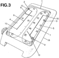
- figure 3 is shown, in a perspective view, the arrangement of a wrist watch according to the present invention, with a dial like the one shown in figure 1 and with two mechanisms (not shown), for example of the type shown in figure 2, incorporated inside the case, one of said mechanisms driving the hour hand 8 and the other driving the minute hand 9.
- FIGs 4A, 4B taken together show the general arrangement of a dial 100 having two scales 101, 102 equivalent to the scales 2, 3, shown in figures 1 and 3 (for the sake of simplicity only the mechanism at the left of figures 4A, 4B will be disclosed).
- a hand 103 for indicating hours along the path or scale 102 is mounted on a half-wheel 104, the structure of which will be better disclosed hereinafter, having an internal toothing 105 meshing with a drive pinion 106 rotated in a conventional way as it is well known to a person skilled in the art.
- the half-wheel 104 is pivoted in 107 on a movable carriage 108 that moves along a straight path 109.
- the half-wheel 104 can perform either a rotational motion or a rectilinear motion according to whether the pinion 104 is meshing with the semicircular toothing 105A or with the straight toothing 105B.
- the free end of the hand 103 follows the semicircular path at the top or bottom of the scale 101, while when the pinion 104 engages the toothing 105B, the free end of the hand 103 follows the straight part of the scale 101.
- the wheel 104 is rotatably arranged, as mentioned above, on a sliding carriage 108.
- a pin 120 fostened to the wheel 104 passes through the carriage 108 and carries a hand 121 (103).
Landscapes
- Physics & Mathematics (AREA)
- General Physics & Mathematics (AREA)
- Geometry (AREA)
- Electromechanical Clocks (AREA)
- Control Of Stepping Motors (AREA)
- Electric Clocks (AREA)
- Mobile Radio Communication Systems (AREA)
- Measuring Pulse, Heart Rate, Blood Pressure Or Blood Flow (AREA)
- Oscillators With Electromechanical Resonators (AREA)
- Debugging And Monitoring (AREA)
Abstract
Description
- The present invention relates to a system which causes the hand of a clock or watch to perform a new and original movement differing essentially from that of conventional clocks and watches with so-called "analog" time display.
- As is known, in conventional clocks and watches of the analog type, the hands indicating the hours, the minutes and possibly the seconds move following a circular path, generally following a single scale of indicia on the dial of the clock itself.
- According to the present invention a system is provided capable of causing the hand of a clock to move in a linear manner along a straight guide slot which is equidistant from opposite side portions of a scale indicating the time on the dial of said clock, and rotating when said hand reaches the top and bottom of said straight guide slot.
- The present invention will be better described below through the description of preferred embodiments thereof, given as a non-limiting example, and with reference to the enclosed figures, in which:
- figure 1 is a plan view of a clock dial according to the present invention;
- figure 2 is a perspective view of a mechanism for moving the hands of a clock or watch according to a first embodiment of the present invention;
- figure 3 is a perspective view of a wrist watch according to the present invention;
- figures 4A and 4B, taken together, show a second example of a mechanism for moving the hands of a clock or watch according to the invention;
- figure 5 shows a detail of the driving mechanism of figure 4A;
- figure 6 shows a sectional view taken along lines VI-VI of figure 5;
- figure 7 shows another detail of the driving mechanism of figure 4A;
- figure 8 shows another detail of the driving mechanism of figure 4A; and
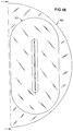
- figure 9 shows a sectional view of the detail shown in figure 8.
- Reference is made to figure 1, in which is shown the
dial 1 of a clock or watch using a system according to the present invention, said dial comprising two distinct and separate scales set side by side, of which a first scale, generally indicated with 2, relating to the hours and marked in part with Roman numerals and the rest with respective dots, and a second scale, generally indicated with 3, relating to the minutes, with numbers, for example, marked every five minutes and the remaining minutes indicated by respective dots. - The two
scales respective outlines - It must be specified that, although in
dial 1 of this embodiment of the invention scales with indicia relating to hours and minutes have been given, it is also possible to provide on the dial itself, as well as the scales mentioned above, scale for seconds next to that for hours or that for minutes, or alternatively the scale for hours alone. - Along the longitudinal axis line of each
scale 2 and 3 aslot 6 and respectively 7 is made in thedial 1, said slot being of the same length as the straight sections of theoutlines circular enlargement 10 in correspondence with both of the ends. - In each of the
slots 6, 7 ahand outlines hand respective slot circular enlargment 10, so as to indicate the hours marked on the substantially semicircular upper or lower section of therespective outline - With reference to figure 2, a description will now be given of an embodiment of the mechanism mentioned above for the movement of each of the
hands - The mechanism mentioned above for the movement of each
hand rollers 11 and 13 a flatcircular belt 14 is positioned, along the longitudinal axis of which is made a sequence ofholes 15, having a diameter slightly larger that that of thepins 12 onroller 11, placed at intervals equal to those between said pins, saidholes 15 being suitable to be engaged by saidpins 12 to cause thebelt 14 to turn following rotation of thedriving roller 11. - On the outer side of the
belt 14, perpendicularly to its upper and lower edges, arod 16 is fixed, having a first section 17 bent into a right angle, the length of said first section being equal to the radius of therollers second section 18, parallel to the axis of therollers slot second section 18, thehand - With the mechanism as above, the movement of the
rod 16 carried by the straight sections of thebelt 14 becomes the linear movement of thehand slot rod 16 reaches the radius of the drivenroller 13 perpendicular to the ascending section of said belt, or in correspondence with the edge of the radius of thedriving roller 11 perpendicular to the descending section of said belt, which correspond, respectively, to the arrival of thehand slot belt 14 continues, respectively, around the drivenroller 13 or around thedriving roller 11, will make a turn, with thesection 18 of therod 16 turning in the upper or lowercircular enlargement 10, in view of the fact that the length of section 17 of therod 16 and the radius of therollers section 18 of therod 16, during the movement ofbelt 14 around therollers - For rotation of the
driving roller 11 it is possible to provide a toothed wheel (not shown) keyed to the shaft of said roller, suitable to engage with a pinion keyed to the central pin for rotation of the hands in a conventional clock, or alternatively it is possible to provide a stepper motor for said roller. - In figure 3 is shown, in a perspective view, the arrangement of a wrist watch according to the present invention, with a dial like the one shown in figure 1 and with two mechanisms (not shown), for example of the type shown in figure 2, incorporated inside the case, one of said mechanisms driving the
hour hand 8 and the other driving theminute hand 9. - Now, with reference to figures 4A, 4B, 5, 6, 7, 8 another embodiment for driving the hands of a clock or watch will be disclosed.
- Figures 4A, 4B taken together show the general arrangement of a
dial 100 having twoscales scales - A
hand 103 for indicating hours along the path orscale 102 is mounted on a half-wheel 104, the structure of which will be better disclosed hereinafter, having aninternal toothing 105 meshing with adrive pinion 106 rotated in a conventional way as it is well known to a person skilled in the art. - The half-
wheel 104 is pivoted in 107 on amovable carriage 108 that moves along astraight path 109. - The half-
wheel 104 can perform either a rotational motion or a rectilinear motion according to whether thepinion 104 is meshing with the semicircular toothing 105A or with the straight toothing 105B. - When the
pinion 104 engages the toothing 105A, the free end of thehand 103 follows the semicircular path at the top or bottom of thescale 101, while when thepinion 104 engages the toothing 105B, the free end of thehand 103 follows the straight part of thescale 101. - In order that the half-
wheel 104 follows the intended motion, several mechanical constraints are provided as follows: - for maintaining the correct engagement with the
pinion 106, the latter is provided with aretaining pin 109′ that runs along agroove 110′ present in thewheel 104. As can be more clearly seen in figures 5 and 6, the toothing 111 of thepinion 106 meshes with theinternal toothing 112 of the half-wheel 104. - With the cooperation of the
toothings groove arrangement 109′/110′ a continuous engagement of thewheel 104 with thepinion 106 will be maintained. - This sole constraint, however, will not be sufficient for guiding the
wheel 104. In order to assure the complete motion of thewheel 104, there is provided an arrangement comprising two pairs ofguides pin 117 can ride (see figure 7 for more details). - When the
wheel 104 moves clockwise as shown by thearrow 118, at a given moment (i. e. at the end of the circular motion of the wheel 104) thepin 107 will engage the part 114A of theguide 114; at the same time, thepinion 106 will engage the rectilinear toothing 105B of thewheel 104, so that the wheel 104 (and the hand 103) will start a motion upwards as is shown by thearrow 119. - The same state of affairs will occur at the engagement by
guide pin 117 of theguides wheel 104 from its topmost position will start to descent with the free end of thehand 103 following the right part of thepath 101. - The
wheel 104 is rotatably arranged, as mentioned above, on asliding carriage 108. Apin 120 fostened to thewheel 104 passes through thecarriage 108 and carries a hand 121 (103). - This is better shown in figures 8 and 9, where an enlarged representation of this structure is shown.
- The operation of the mechanism thus disclosed should be clear. In the situation shown in fugre 4A, the
carriage 108 is temporarily standing in the position shown, while thewheel 104 rotates through 180° in a clockwise direction, carrying with it the hand 103 (121). - When the toothing 105B becomes parallel to the
path 109, thecarriage 108 will slide along thepath 109 rising towards the top of the drawing of figures 4A, 4B, carrying the hand 103 (121) along a rectilinear path. - The converse occurs when the
carriage 108 has reached its topmost position, where thewheel 104 will have its toothing 105A engaged by thepinion 106 performing thus a rotation through 180°. The cycle will repeat itself for the operation of a clock or watch.
Claims (6)
- An analog type clock or watch having at least one hand and a scale of indicia showing time, characterized in that it comprises means for moving said at least one hand along a closed, non-circular path, having a first and a second straight section, parallel to each other and joined respectively at their ends by corresponding semicircular portions, so that the free end of said at least one hand travels along two straight sections and makes two 180 degree movements as it turns to indicate the time; said means comprising a motor element driven at a constant speed, said element being per se known, arranged so as to actuate a driven element to which the inner end of said hand is fixed; said driven element cooperating with guide means arranged to impart an alternately translatory and rotatory movement to said driven element, so that the free end of said hand follows said closed, non-circular route, pointing in succession to marks indicating the time arranged on the dial of said clock or watch.
- An analog type clock or watch according to claim 1, in qhich said means for moving said hand along a slot centered on said path and for turning said hand when it reaches the end of said slot comprise a continuous, flexible transmission element positioned between a driver roller and a driven roller; a rod, fixed to the outer surface of said flexible element perpendicularly to its upper and lower edges, said rod having on it upper part a first section bent into a right angle, the length of said section being equal to the length of the radius of said rollers, and a second section extending perpendicularly from the free end of said first section, said second section being parallel to the axis of said rollers, and engaged with said slot, and said hand being fixed onto the free end of said second section.
- An analog type clock or watch according to claim 2, in which said driving roller, in order to operate, is connected to the central pin destined for rotation of the hands in a conventional clock mechanism.
- An analog type clock or watch according to any of the preceding claims, in which said clock dial has two distinct and separate scales of indicia, one for the hours and one for the minutes.
- An analog type clock or watch according to claim 1, characterized in that said means for moving said hand along said slot and for turning said hand when it reaches the end of said slot comprise a half-wheel having a toothing meshing with a drive pinion, said hald-wheel being journalled on a journal carried by a sliding carriage movable along said slot; said half-wheel also carrying a pin supporting said hand; the arrangement being such that when said half-wheel meshes with said drive pinion along the semicircular part of said toothing, the hand performs a half-turn motion, while when said half-wheel meshes with said drive pinion along the rectilinear part of said toothing, the hand runs along a straight path parallel to said slot.
- An analog type clock or watch, according to claims 1 and 5, comprising an additional means for driving a second hand along a closed path similar to said means for moving said first named hand.
Applications Claiming Priority (2)
| Application Number | Priority Date | Filing Date | Title |
|---|---|---|---|
| ITRM910201A IT1244953B (en) | 1991-03-27 | 1991-03-27 | SYSTEM FOR THE MOVEMENT OF CLOCK HANDS. |
| ITRM910201 | 1991-03-27 |
Publications (2)
| Publication Number | Publication Date |
|---|---|
| EP0509965A1 true EP0509965A1 (en) | 1992-10-21 |
| EP0509965B1 EP0509965B1 (en) | 1997-10-15 |
Family
ID=11400007
Family Applications (1)
| Application Number | Title | Priority Date | Filing Date |
|---|---|---|---|
| EP92830151A Expired - Lifetime EP0509965B1 (en) | 1991-03-27 | 1992-03-26 | A system for the movement of the hands of a clock or watch |
Country Status (10)
| Country | Link |
|---|---|
| US (1) | US5199006A (en) |
| EP (1) | EP0509965B1 (en) |
| JP (1) | JPH0736318Y2 (en) |
| KR (1) | KR960003001Y1 (en) |
| AT (1) | ATE159352T1 (en) |
| DE (1) | DE69222676T2 (en) |
| DK (1) | DK0509965T3 (en) |
| ES (1) | ES2109330T3 (en) |
| GR (1) | GR3025776T3 (en) |
| IT (1) | IT1244953B (en) |
Cited By (9)
| Publication number | Priority date | Publication date | Assignee | Title |
|---|---|---|---|---|
| EP1520214A2 (en) | 2002-07-09 | 2005-04-06 | Tag-Heuer Sa | Clock movement for wristwatch |
| USD554004S1 (en) * | 2005-04-01 | 2007-10-30 | Anton Kraft | Watch |
| EP1884841A1 (en) * | 2006-08-01 | 2008-02-06 | Agenhor SA | Timepiece movement allowing control of a display mechanism following a complex path and timepiece incorporating said movement |
| WO2008102399A3 (en) * | 2007-02-20 | 2009-04-02 | Davide Regoli | Modular construction to produce parabolic movement in large and micron mechanisms |
| WO2008102400A3 (en) * | 2007-02-20 | 2009-05-14 | Davide Regoli | Modular construction to produce linear movement in large and micron mechanisms |
| EP1760546A3 (en) * | 2005-09-05 | 2010-01-20 | Richemont International S.A. | Linear time display |
| EP3460587A1 (en) * | 2017-09-20 | 2019-03-27 | Carlo Ferrara SA | Guiding system |
| EP3620865A1 (en) * | 2018-09-05 | 2020-03-11 | The Swatch Group Research and Development Ltd | Mechanical or electromechanical timepiece with mysterious drive mechanism |
| CN112947025A (en) * | 2019-12-11 | 2021-06-11 | 天津海鸥表业集团有限公司 | Linear time indicating device |
Families Citing this family (7)
| Publication number | Priority date | Publication date | Assignee | Title |
|---|---|---|---|---|
| US5299178A (en) * | 1993-08-06 | 1994-03-29 | Jaroslav Belik | Clock |
| USD361537S (en) | 1993-10-14 | 1995-08-22 | Carlo Ferrara | Watch dial |
| US5640372A (en) * | 1996-04-19 | 1997-06-17 | Thackara; John I. | Rotationally symmetric timepiece |
| US6256265B1 (en) | 1999-10-06 | 2001-07-03 | Richard J. Sepulveda | Time display |
| USD481643S1 (en) | 2002-05-17 | 2003-11-04 | Journe Francois-Paul | Watch dial |
| DE10325793A1 (en) * | 2003-06-05 | 2004-12-30 | Borg Instruments Ag | linear pointer |
| US7515508B1 (en) * | 2008-03-12 | 2009-04-07 | Timex Group B.V. | Indicator assembly for a wearable electronic device |
Citations (4)
| Publication number | Priority date | Publication date | Assignee | Title |
|---|---|---|---|---|
| DE218946C (en) * | ||||
| FR1001877A (en) * | 1949-12-09 | 1952-02-28 | Improvements to clocks | |
| FR2450476A1 (en) * | 1979-03-02 | 1980-09-26 | Ingendahl Kurt | WATCH WITH IMPROVED DISPLAY |
| EP0419421A1 (en) * | 1989-09-20 | 1991-03-27 | van Marcke-Klar, Gabriele | Watch with a linear scale |
Family Cites Families (8)
| Publication number | Priority date | Publication date | Assignee | Title |
|---|---|---|---|---|
| US2221413A (en) * | 1939-02-28 | 1940-11-12 | Jacob L Schanz | Straight-line clock |
| US3852949A (en) * | 1973-06-08 | 1974-12-10 | R Sayler | Plural cycle display device |
| US3956879A (en) * | 1974-02-11 | 1976-05-18 | Bailey James R | Time indicating device |
| GB1540631A (en) * | 1975-03-03 | 1979-02-14 | Ingendahl K | Clock |
| US4103484A (en) * | 1976-07-22 | 1978-08-01 | Bailey James R | Time indicating device |
| FR2450426A1 (en) * | 1979-02-28 | 1980-09-26 | Landriault Olivier | Solar energy trap panel - covered with retractable polyethylene film, to keep the exposed face of the trap plane and smooth |
| JPS55150383U (en) * | 1979-04-17 | 1980-10-29 | ||
| JPH0732901Y2 (en) * | 1988-06-30 | 1995-07-31 | スズキ株式会社 | Soundproof engine work machine |
-
1991
- 1991-03-27 IT ITRM910201A patent/IT1244953B/en active IP Right Grant
-
1992
- 1992-03-25 US US07/857,158 patent/US5199006A/en not_active Expired - Lifetime
- 1992-03-26 DE DE69222676T patent/DE69222676T2/en not_active Expired - Fee Related
- 1992-03-26 KR KR92004752U patent/KR960003001Y1/en not_active Expired - Fee Related
- 1992-03-26 EP EP92830151A patent/EP0509965B1/en not_active Expired - Lifetime
- 1992-03-26 DK DK92830151.4T patent/DK0509965T3/en active
- 1992-03-26 AT AT92830151T patent/ATE159352T1/en not_active IP Right Cessation
- 1992-03-26 ES ES92830151T patent/ES2109330T3/en not_active Expired - Lifetime
- 1992-03-27 JP JP1992016843U patent/JPH0736318Y2/en not_active Expired - Lifetime
-
1997
- 1997-12-23 GR GR970403427T patent/GR3025776T3/en unknown
Patent Citations (4)
| Publication number | Priority date | Publication date | Assignee | Title |
|---|---|---|---|---|
| DE218946C (en) * | ||||
| FR1001877A (en) * | 1949-12-09 | 1952-02-28 | Improvements to clocks | |
| FR2450476A1 (en) * | 1979-03-02 | 1980-09-26 | Ingendahl Kurt | WATCH WITH IMPROVED DISPLAY |
| EP0419421A1 (en) * | 1989-09-20 | 1991-03-27 | van Marcke-Klar, Gabriele | Watch with a linear scale |
Cited By (18)
| Publication number | Priority date | Publication date | Assignee | Title |
|---|---|---|---|---|
| US8498180B2 (en) | 2002-07-09 | 2013-07-30 | Lvmh Swiss Manufactures Sa | Clock work movement for a wristwatch |
| EP1520214A2 (en) | 2002-07-09 | 2005-04-06 | Tag-Heuer Sa | Clock movement for wristwatch |
| US8976629B2 (en) | 2002-07-09 | 2015-03-10 | Lvmh Swiss Manufactures Sa | Clock work movement for a wristwatch |
| US7697376B2 (en) | 2002-07-09 | 2010-04-13 | Tag Heuer Sa | Clockwork movement for a wristwatch |
| EP2259157A3 (en) * | 2002-07-09 | 2011-01-26 | LVMH Swiss Manufactures SA | Clockwork for wristwatch |
| USD554004S1 (en) * | 2005-04-01 | 2007-10-30 | Anton Kraft | Watch |
| EP1760546A3 (en) * | 2005-09-05 | 2010-01-20 | Richemont International S.A. | Linear time display |
| EP1884841A1 (en) * | 2006-08-01 | 2008-02-06 | Agenhor SA | Timepiece movement allowing control of a display mechanism following a complex path and timepiece incorporating said movement |
| WO2008015568A3 (en) * | 2006-08-01 | 2008-04-24 | Agenhor Sa | Timepiece movement for driving a display element along a complex path and timepiece comprising such a movement |
| US7969824B2 (en) | 2006-08-01 | 2011-06-28 | Agenhor Sa | Timepiece movement for driving a display element along a complex path and timepiece comprising such a movement |
| WO2008102399A3 (en) * | 2007-02-20 | 2009-04-02 | Davide Regoli | Modular construction to produce parabolic movement in large and micron mechanisms |
| WO2008102400A3 (en) * | 2007-02-20 | 2009-05-14 | Davide Regoli | Modular construction to produce linear movement in large and micron mechanisms |
| EP3460587A1 (en) * | 2017-09-20 | 2019-03-27 | Carlo Ferrara SA | Guiding system |
| CH714177A1 (en) * | 2017-09-20 | 2019-03-29 | Carlo Ferrara Sa C/O Arc Fiduciaire Sa | Guiding system for timepiece. |
| EP3620865A1 (en) * | 2018-09-05 | 2020-03-11 | The Swatch Group Research and Development Ltd | Mechanical or electromechanical timepiece with mysterious drive mechanism |
| US11454935B2 (en) | 2018-09-05 | 2022-09-27 | The Swatch Group Research And Development Ltd | Mystery-drive mechanical or electromechanical timepiece |
| CN112947025A (en) * | 2019-12-11 | 2021-06-11 | 天津海鸥表业集团有限公司 | Linear time indicating device |
| CN112947025B (en) * | 2019-12-11 | 2024-08-23 | 天津海鸥表业集团有限公司 | A linear time indicating device |
Also Published As
| Publication number | Publication date |
|---|---|
| ITRM910201A0 (en) | 1991-03-27 |
| DE69222676T2 (en) | 1998-04-30 |
| DK0509965T3 (en) | 1998-04-27 |
| IT1244953B (en) | 1994-09-13 |
| DE69222676D1 (en) | 1997-11-20 |
| KR960003001Y1 (en) | 1996-04-12 |
| GR3025776T3 (en) | 1998-03-31 |
| KR920018531U (en) | 1992-10-19 |
| ITRM910201A1 (en) | 1992-09-27 |
| ES2109330T3 (en) | 1998-01-16 |
| EP0509965B1 (en) | 1997-10-15 |
| JPH0736318Y2 (en) | 1995-08-16 |
| ATE159352T1 (en) | 1997-11-15 |
| US5199006A (en) | 1993-03-30 |
| JPH04126195U (en) | 1992-11-17 |
Similar Documents
| Publication | Publication Date | Title |
|---|---|---|
| US5199006A (en) | System for the movement of the hands of a clock or watch | |
| RU2310898C2 (en) | Clockwork for wristwatch | |
| US7969824B2 (en) | Timepiece movement for driving a display element along a complex path and timepiece comprising such a movement | |
| EP1812829B1 (en) | Timepiece movement and display | |
| JP4603539B2 (en) | Gear unit for wristwatch movement | |
| US5086416A (en) | Display module for watch movement | |
| CN111025877B (en) | Mechanical digital display for a timepiece | |
| JP2011128027A (en) | Calendar timepiece | |
| US20060007787A1 (en) | Method and device for displaying a moon image cycle, in particular for a watch | |
| EP0327513B1 (en) | A timepiece | |
| US5379272A (en) | Moslem calendar | |
| EP0438975B1 (en) | Machine with intermittently rotary workpiece-holding table for performing with great rapidity the working and assembly of pieces requiring high-precision | |
| US5222051A (en) | Analogic display module for a watch movement | |
| JP2022098430A (en) | Multiple jump timepiece display mechanism | |
| GB2257548A (en) | Setting mechanism for a timepiece. | |
| KR19990006733A (en) | Gear-separating device for a series of gears in the watch | |
| US12541175B2 (en) | Three-dimensional karussel for a horological movement | |
| CN1044715A (en) | Clock and watch three hand movement with stepper motor | |
| JP2007071875A (en) | Linear time display | |
| CN1573621A (en) | Analog display device | |
| JP2026500437A (en) | Time display device | |
| US3972179A (en) | Changeable display device | |
| HK40026300A (en) | Mechanical digital display for timepieces | |
| HK40026300B (en) | Mechanical digital display for timepieces | |
| JP2025150728A (en) | Switch mechanism, watch movement and watch |
Legal Events
| Date | Code | Title | Description |
|---|---|---|---|
| PUAI | Public reference made under article 153(3) epc to a published international application that has entered the european phase |
Free format text: ORIGINAL CODE: 0009012 |
|
| AK | Designated contracting states |
Kind code of ref document: A1 Designated state(s): AT BE CH DE DK ES FR GB GR IT LI LU NL PT SE |
|
| 17P | Request for examination filed |
Effective date: 19930310 |
|
| 17Q | First examination report despatched |
Effective date: 19960508 |
|
| GRAG | Despatch of communication of intention to grant |
Free format text: ORIGINAL CODE: EPIDOS AGRA |
|
| GRAH | Despatch of communication of intention to grant a patent |
Free format text: ORIGINAL CODE: EPIDOS IGRA |
|
| GRAH | Despatch of communication of intention to grant a patent |
Free format text: ORIGINAL CODE: EPIDOS IGRA |
|
| GRAA | (expected) grant |
Free format text: ORIGINAL CODE: 0009210 |
|
| AK | Designated contracting states |
Kind code of ref document: B1 Designated state(s): AT BE CH DE DK ES FR GB GR IT LI LU NL PT SE |
|
| REF | Corresponds to: |
Ref document number: 159352 Country of ref document: AT Date of ref document: 19971115 Kind code of ref document: T |
|
| REG | Reference to a national code |
Ref country code: CH Ref legal event code: NV Representative=s name: PATENTANWAELTE SCHAAD, BALASS, MENZL & PARTNER AG Ref country code: CH Ref legal event code: EP |
|
| REF | Corresponds to: |
Ref document number: 69222676 Country of ref document: DE Date of ref document: 19971120 |
|
| ITF | It: translation for a ep patent filed | ||
| REG | Reference to a national code |
Ref country code: ES Ref legal event code: FG2A Ref document number: 2109330 Country of ref document: ES Kind code of ref document: T3 |
|
| ET | Fr: translation filed | ||
| REG | Reference to a national code |
Ref country code: PT Ref legal event code: SC4A Free format text: AVAILABILITY OF NATIONAL TRANSLATION Effective date: 19971217 |
|
| REG | Reference to a national code |
Ref country code: DK Ref legal event code: T3 |
|
| PLBE | No opposition filed within time limit |
Free format text: ORIGINAL CODE: 0009261 |
|
| 26N | No opposition filed | ||
| REG | Reference to a national code |
Ref country code: GB Ref legal event code: IF02 |
|
| PGFP | Annual fee paid to national office [announced via postgrant information from national office to epo] |
Ref country code: DK Payment date: 20040123 Year of fee payment: 13 |
|
| PGFP | Annual fee paid to national office [announced via postgrant information from national office to epo] |
Ref country code: SE Payment date: 20040130 Year of fee payment: 13 Ref country code: GR Payment date: 20040130 Year of fee payment: 13 |
|
| PGFP | Annual fee paid to national office [announced via postgrant information from national office to epo] |
Ref country code: LU Payment date: 20040211 Year of fee payment: 13 |
|
| PGFP | Annual fee paid to national office [announced via postgrant information from national office to epo] |
Ref country code: AT Payment date: 20040308 Year of fee payment: 13 |
|
| PGFP | Annual fee paid to national office [announced via postgrant information from national office to epo] |
Ref country code: NL Payment date: 20040416 Year of fee payment: 14 |
|
| PG25 | Lapsed in a contracting state [announced via postgrant information from national office to epo] |
Ref country code: LU Free format text: LAPSE BECAUSE OF NON-PAYMENT OF DUE FEES Effective date: 20050326 Ref country code: AT Free format text: LAPSE BECAUSE OF NON-PAYMENT OF DUE FEES Effective date: 20050326 |
|
| PG25 | Lapsed in a contracting state [announced via postgrant information from national office to epo] |
Ref country code: SE Free format text: LAPSE BECAUSE OF NON-PAYMENT OF DUE FEES Effective date: 20050327 |
|
| PG25 | Lapsed in a contracting state [announced via postgrant information from national office to epo] |
Ref country code: DK Free format text: LAPSE BECAUSE OF NON-PAYMENT OF DUE FEES Effective date: 20050331 |
|
| PG25 | Lapsed in a contracting state [announced via postgrant information from national office to epo] |
Ref country code: NL Free format text: LAPSE BECAUSE OF NON-PAYMENT OF DUE FEES Effective date: 20051001 |
|
| PG25 | Lapsed in a contracting state [announced via postgrant information from national office to epo] |
Ref country code: GR Free format text: LAPSE BECAUSE OF NON-PAYMENT OF DUE FEES Effective date: 20051004 |
|
| EUG | Se: european patent has lapsed | ||
| NLV4 | Nl: lapsed or anulled due to non-payment of the annual fee |
Effective date: 20051001 |
|
| REG | Reference to a national code |
Ref country code: DK Ref legal event code: EBP |
|
| PGFP | Annual fee paid to national office [announced via postgrant information from national office to epo] |
Ref country code: FR Payment date: 20060327 Year of fee payment: 15 |
|
| PGFP | Annual fee paid to national office [announced via postgrant information from national office to epo] |
Ref country code: CH Payment date: 20060418 Year of fee payment: 15 |
|
| PGFP | Annual fee paid to national office [announced via postgrant information from national office to epo] |
Ref country code: BE Payment date: 20060502 Year of fee payment: 15 |
|
| PGFP | Annual fee paid to national office [announced via postgrant information from national office to epo] |
Ref country code: PT Payment date: 20060921 Year of fee payment: 15 |
|
| PG25 | Lapsed in a contracting state [announced via postgrant information from national office to epo] |
Ref country code: PT Free format text: LAPSE BECAUSE OF NON-PAYMENT OF DUE FEES Effective date: 20070926 |
|
| REG | Reference to a national code |
Ref country code: PT Ref legal event code: MM4A Free format text: LAPSE DUE TO NON-PAYMENT OF FEES Effective date: 20070926 |
|
| REG | Reference to a national code |
Ref country code: CH Ref legal event code: PL |
|
| BERE | Be: lapsed |
Owner name: *FERRARA CARLO Effective date: 20070331 |
|
| PG25 | Lapsed in a contracting state [announced via postgrant information from national office to epo] |
Ref country code: BE Free format text: LAPSE BECAUSE OF NON-PAYMENT OF DUE FEES Effective date: 20070331 |
|
| REG | Reference to a national code |
Ref country code: FR Ref legal event code: ST Effective date: 20071130 |
|
| PG25 | Lapsed in a contracting state [announced via postgrant information from national office to epo] |
Ref country code: LI Free format text: LAPSE BECAUSE OF NON-PAYMENT OF DUE FEES Effective date: 20070331 Ref country code: CH Free format text: LAPSE BECAUSE OF NON-PAYMENT OF DUE FEES Effective date: 20070331 |
|
| PG25 | Lapsed in a contracting state [announced via postgrant information from national office to epo] |
Ref country code: FR Free format text: LAPSE BECAUSE OF NON-PAYMENT OF DUE FEES Effective date: 20070402 |
|
| PGFP | Annual fee paid to national office [announced via postgrant information from national office to epo] |
Ref country code: ES Payment date: 20090925 Year of fee payment: 18 |
|
| PGFP | Annual fee paid to national office [announced via postgrant information from national office to epo] |
Ref country code: GB Payment date: 20090928 Year of fee payment: 18 |
|
| PGFP | Annual fee paid to national office [announced via postgrant information from national office to epo] |
Ref country code: DE Payment date: 20090924 Year of fee payment: 18 |
|
| PGFP | Annual fee paid to national office [announced via postgrant information from national office to epo] |
Ref country code: IT Payment date: 20090929 Year of fee payment: 18 |
|
| GBPC | Gb: european patent ceased through non-payment of renewal fee |
Effective date: 20100326 |
|
| PG25 | Lapsed in a contracting state [announced via postgrant information from national office to epo] |
Ref country code: DE Free format text: LAPSE BECAUSE OF NON-PAYMENT OF DUE FEES Effective date: 20101001 |
|
| PG25 | Lapsed in a contracting state [announced via postgrant information from national office to epo] |
Ref country code: GB Free format text: LAPSE BECAUSE OF NON-PAYMENT OF DUE FEES Effective date: 20100326 Ref country code: IT Free format text: LAPSE BECAUSE OF NON-PAYMENT OF DUE FEES Effective date: 20100326 |
|
| REG | Reference to a national code |
Ref country code: ES Ref legal event code: FD2A Effective date: 20110418 |
|
| PG25 | Lapsed in a contracting state [announced via postgrant information from national office to epo] |
Ref country code: ES Free format text: LAPSE BECAUSE OF NON-PAYMENT OF DUE FEES Effective date: 20110404 |
|
| PG25 | Lapsed in a contracting state [announced via postgrant information from national office to epo] |
Ref country code: ES Free format text: LAPSE BECAUSE OF NON-PAYMENT OF DUE FEES Effective date: 20100327 |