EP0511863B1 - Unité d'entraînement de disque magnétique - Google Patents
Unité d'entraînement de disque magnétique Download PDFInfo
- Publication number
- EP0511863B1 EP0511863B1 EP92303908A EP92303908A EP0511863B1 EP 0511863 B1 EP0511863 B1 EP 0511863B1 EP 92303908 A EP92303908 A EP 92303908A EP 92303908 A EP92303908 A EP 92303908A EP 0511863 B1 EP0511863 B1 EP 0511863B1
- Authority
- EP
- European Patent Office
- Prior art keywords
- offset
- data
- head
- servo
- servo information
- Prior art date
- Legal status (The legal status is an assumption and is not a legal conclusion. Google has not performed a legal analysis and makes no representation as to the accuracy of the status listed.)
- Expired - Lifetime
Links
Images


Classifications
-
- G—PHYSICS
- G11—INFORMATION STORAGE
- G11B—INFORMATION STORAGE BASED ON RELATIVE MOVEMENT BETWEEN RECORD CARRIER AND TRANSDUCER
- G11B5/00—Recording by magnetisation or demagnetisation of a record carrier; Reproducing by magnetic means; Record carriers therefor
- G11B5/48—Disposition or mounting of heads or head supports relative to record carriers ; arrangements of heads, e.g. for scanning the record carrier to increase the relative speed
- G11B5/58—Disposition or mounting of heads or head supports relative to record carriers ; arrangements of heads, e.g. for scanning the record carrier to increase the relative speed with provision for moving the head for the purpose of maintaining alignment of the head relative to the record carrier during transducing operation, e.g. to compensate for surface irregularities of the latter or for track following
- G11B5/596—Disposition or mounting of heads or head supports relative to record carriers ; arrangements of heads, e.g. for scanning the record carrier to increase the relative speed with provision for moving the head for the purpose of maintaining alignment of the head relative to the record carrier during transducing operation, e.g. to compensate for surface irregularities of the latter or for track following for track following on disks
- G11B5/59627—Aligning for runout, eccentricity or offset compensation
Definitions
- the present invention relates to magnetic disk drive units.
- the data head which is moveable over the data surface, is controlled to be on-track based only on the servo information recorded on a servo surface.
- a control circuit is used with a magnetic disk having a relatively high track density (i.e. with such narrow track gaps) the data head tends to be off-track and cannot read the data on the data surface if the operating environment of the magnetic disk unit, especially the ambient temperature, changes from low to high or vice versa.
- a previously-considered head positioning circuit intended to alleviate this problem, corrects an offset of the data head from a desired on-track position by recording servo information on the data surface as well as on the servo surface and by using the servo information on both the servo and data surfaces to prevent offset of the data head.
- head positioning control is done by performing an offset detection at predetermined time intervals (depending upon the change of ambient temperature), storing the offset thus detected in a memory for each head, and reading the appropriate offset from the memory at the time of data writing or reading to correct the offset.
- this offset detection is done by the data head to read the servo information on the data surface and detect an offset of the data heads from the servo head.
- the servo head under on-track control, is in fact likely to be offtrack due to external vibration, poor accuracy of control or the like so that the offset of the data head is detected at a time when the servo head is off-track. No accurate correction of the data head offset can be accordingly be done.
- magnetic disk unit for example, four magnetic disks are mounted on the rotating shaft of a spindle motor and thus rotated at a predetermined speed.
- the upper three have a data surface formed on either face, upper and lower, thereof and the lowest disk has a data surface formed on the upper face thereof and a servo surface on the lower face thereof.
- Data heads are provided in opposition to the data surfaces of the magnetic disks and a servo head is provided opposite the servo surface.
- the data heads and servo head are arranged in the form of a comb and are driven together by a voice coil motor (will be referred to as "VCM” hereinafter) and move in a direction transverse to the tracks on the magnetic disks.
- VCM voice coil motor
- the servo surface over which the servo head is positioned has servo information recorded in all the cylinders (cylinder: all tracks accessed by all the magnetic heads when a comb is in a certain position) thereof, and a position signal indicative of the position of the servo head on the track is provided based on a signal read by the servo head.
- the data surfaces of the data heads have recorded in the free space of a predetermined cylinder track or of all the cylinder sectors thereof servo information used to detect an offset of the data heads.
- the offset of the data head from the servo head is detected based on the servo information read by the data head from the data surface.
- the data head can be accurately positioned in the cylinder centre by displacing the heads (offset correction) to eliminate the offset.
- the above-discussed previously-considered offset detecting circuit has the disadvantage that the data heads are prone to oscillate due to disturbances or poor accuracy of positioning control during detection of a data head offset, and detection of a data head offset done at the time of such oscillation will result in a measurement error.
- the offset of the data head from the servo head should be detected, but the offset of the data head from the cylinder center is detected in a condition where the servo head is offset from the cylinder center because of the oscillation of the heads.
- the data head will be offset from the cylinder center so that the offset correction will itself cause an offset of the data head.
- JP-A-63 273 284 discloses a data head offset detecting circuit for a magnetic disk unit, according to the preamble of accompanying claim 1.
- a position signal of the servo head is formed based on the peak value of the servo signal.
- this position signal represents a whole number of tracks rather than a deviation of the servo head from the on-track position.
- EP-A-0 285 452 discloses a similar offset detecting circuit in which a position signal of the servo head is formed based on the peak value of the servo signal.
- the present invention also embraces a magnetic disk unit using the offset detecting circuit.
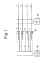
- Figure 1 shows a schematic view of a magnetic disk unit; 1 denotes a magnetic disk, 2 denotes a data head, 34 denotes a servo head, 36 denotes a voice coil motor (VCM), and 38 denotes a spindle motor.
- VCM voice coil motor
- Figures 2A, 2B, and 2C are explanatory diagrams illustrating an offset detection of the data head 2, and as shown in Fig. 2A, if the servo head 34 and the data head 2 are positioned on the cylinder center, the offset correction is not necessary. In practice, however, the data head 2 will be off the cylinder centre on which the servo head 34 is positioned as shown in Fig. 2B because of the difference in the expansion coefficient between the metals used to form the head actuator and the like.
- the offset ⁇ of the data head 2 from the servo head 34 is detected on the basis of the servo information read by the data head 2 on the data surface.
- the data head 2 can be accurately positioned in the cylinder centre by displacing the heads (offset correction) to eliminate the offset ⁇ as shown in Fig. 2C.
- the data heads can oscillate because of disturbances or poor accuracy of positioning control during detection of a data head offset, and detection of a data head offset done at the time of such oscillation will result in a measurement error as shown in Fig. 3A.
- the offset ⁇ of the data head 2 from the servo head 34 should be detected, but the offset ⁇ of the data head 2 from the cylinder center is detected in a condition where the servo head 34 is offset by ⁇ from the cylinder center because of the oscillation of the heads.
- the data head 2 will be offset from the cylinder center as shown in Fig. 3B so that the offset correction will cause a further offset of the data head 2.
- Figure 4 shows a data head offset detecting circuit for use in a magnetic disk unit, which uses the servo information on both the servo surface and data surfaces of disk media 1 to correct the offset of data heads 2.
- the above circuit comprises a first offset detector 3 that detects an offset ⁇ of data heads 2 based on the servo information read by the data heads 2 from the data surfaces; a second offset detector 4 that detects an offset ⁇ of a servo head 34 based on the servo information read by the servo head 34 from the servo surface; and an offset calculator for calculating a real offset ⁇ derived from subtraction of the offset ⁇ detected by the second offset detector 4 from the offset ⁇ detected by the first offset detector 3.
- first servo information A offset a predetermined amount outward from the ontrack position and second servo information B offset a predetermined amount inward from the ontrack position are recorded for each sector as servo information on the data surfaces.
- the first offset detector 3 calculates a signal indicative of a difference (V A - V B ) between the first servo information A and second servo information B read by the data heads 2 from the data surfaces and multiplies the difference signal (V A - V B ) by a constant proportion coefficient K to detect the offset ⁇ .
- an offset memory 6 using a RAM that stores for each of the data heads 2 the offset ⁇ calculated by the offset calculator 5.
- the servo information on the data surfaces is recorded for each sector, offsets ⁇ 1 to ⁇ n detected for each sector are averaged for a predetermined number of sectors (N) and stored in the RAM that constitutes the offset memory 6. Thus, the capacity of the RAM is decreased.
- a positioning controller 7 that provides an offset correction at the time of a read or a write operation by the data heads 2 from or onto the data surfaces by reading a mean offset for a to-be-accessed sector and sectors just before and next to that mean offset and determining an offset for the to-be-accessed sector by linear interpolation.
- FIG. 5 A block diagram of a magnetic disk unit embodying the invention is shown in Fig. 5.
- the magnetic disk unit generally consists of a disk controller 12 and disk drive 30.
- the disk controller 12 comprises a control processor 14 that provides a centralized control over the whole magnetic disk unit.
- an interface 16 for connection to the host CPU Connected to the control processor 14 by means of an internal bus 28 are an interface 16 for connection to the host CPU, a drive interface 18 for connection to the disk drive 30, a serial/parallel converter 20, a data transfer buffer 24 and a system storage 26.
- the drive interface 18 conveys control commands from the control processor 14 to the disk drive 30.
- Write or read data is transferred between the serial/parallel converter 20 and the disk drive via a data modem 22.
- the serial/parallel converter 20 and data modem 22 usually form together a VFO (variable frequency oscillator).
- VFO variable frequency oscillator
- Write or read data is once stored into the data transfer buffer 24 and then transferred to the disk drive 30 or host CPU.
- the disk drive 30 has provided therein a drive circuit 32 that rotates a plurality of magnetic disks 1 as memory media by means of a spindle motor (SP) 38 at a constant speed, and the magnetic disks 1 have provided in combination therewith heads that are moved by a voice coil motor (VCM) 36 in a direction transverse to the tracks.
- SP spindle motor
- VCM voice coil motor
- the highest one is a servo head 34 and the rest are data heads 2-1 to 2-n.
- the magnetic disk 1 opposite the servo head 34 is a servo disk having servo information recorded in all cylinder positions (in all track positions) on the servo surface thereof.
- Each of the magnetic disks 1 to or from which the data heads 2-1 to 2-n write or read data has a data surface formed thereon.
- the data surfaces have servo information recorded per sector. More particularly, concerning an arbitrary track on the data surface of the magnetic disk, first servo information A being a predetermined frequency, for example, a maximum write frequency signal, is written in an area X ( ⁇ m) displaced outward from the ontrack position of the data head 2 and second servo information B is similarly written in an area X ( ⁇ m) displaced inward from the ontrack position, following the first servo information A, as shown in Fig. 7.
- first servo information A being a predetermined frequency, for example, a maximum write frequency signal
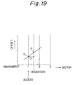
- the method of writing the servo information onto the data surface includes a write to a predetermined track 9 on the data surface 8 as shown in Fig. 8 and a write to free spaces in all the sectors on the data surface 8 as shown in Fig. 9.
- the servo information A is read in a larger amount than the servo information B so that read signal V A will be larger than the read signal V B .
- the servo information B is read in a larger amount than the servo information A so that read signal V B will be larger than the read signal V A .
- a control microprocessor provided in the disk drive 30 reads the difference (V A - V B ) between the read signals V A and V B from the data heads 2 to determine the offset magnitude.
- the relation between the offset and the read difference signal shows a predetermined proportion coefficient (gradient) K as shown in Fig. 10.
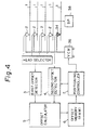
- Fig. 6 is a block diagram showing an example of the constitution of the disk drive 30 in Fig. 5.
- the disk drive 30 has a microprocessor (MPU) 40 as main controller.
- MPU microprocessor
- the disk drive 30 also has a disk enclosure (DE) 56 provided with a head actuator 60 that is driven by VCM 36, and the servo head 34 and data heads 2-1 to 2-n are mounted on the head actuator 60.
- DE disk enclosure
- the servo signal read by the servo head 34 is demodulated by a servo demodulation circuit 42 into two position signals POSN and POSQ, which will be supplied to a conversion circuit 44.
- the conversion circuit 44 produces a (N > Q) and ⁇ (N + Q) > 0 ⁇ signals based on the position signals POSN and POSQ supplied from the servo demodulation circuit 42.
- a track crossing pulse TXPL is produced and a counter counts how many times the head has crossed the track.
- Each signal from the conversion circuit 44 is read into a position detector 46 in the microprocessor 40 to produce position data that varies linearly for each track shown in Fig. 11. Accordingly, the offset ⁇ of the servo head determined based on the servo information on the servo surface during offset detection is obtainable as a position signal shown in Fig. 11.
- CY denotes a cylinder.
- the microprocessor 40 incorporates a servo processor comprising the position detector 46, an add point 48 and a servo compensator 50, and the servo process is executed under control of a program.
- the position detector 46 provides two kinds of control, speed control and position control (ontrack control). Namely, for the head's access to an object track, the head is moved under the speed control, and upon arrival of the head at the object track, the speed control is switched to the position control under which the head is placed ontrack.
- the microprocessor 40 supplies position control data to VCM 36 via the servo compensator 50 so that the position signal delivered from the position detector 46 and shown in Fig. 11 will always be a signal indicative of the track center.
- the servo compensator 50 compensates the advance phase by increasing the gain of the high frequency portion of the servo signal.
- the position control data from the microprocessor 40 are converted to an analog voltage by means of a DA converter 52 and this analog voltage is then amplified in power by means of a power amplifier 54 to drive VCM 36.
- the microprocessor 40 incorporates an offset detector 76, an offset memory 78 and an offset corrector 80.
- the offset detector 76 receives an interrupt that follows a predetermined time sequence and executes an offset detection.
- the time interval of this offset detection is set short immediately after the magnetic disk unit is energized, that is, when the ambient temperature changes significantly, and long, such as once per hour after a lapse of a certain time, that is, when the temperature has become stable.
- the offset detector 76 has been supplied with a difference signal (V A - V B ) that is based on a read signal from any one of the data heads 2-1 to 2-n.
- the data heads 2-1 to 2-n are connected to a head selection circuit 62 which, receiving a select signal from the microprocessor 40, supplies a read signal from one of the data heads to peak hold circuits 64 and 66.
- the peak hold circuit 64 holds the peak value V A of the read signal of the first servo information A recorded on the data surface.
- the peak hold circuit 66 holds the peak value V B of the read signal of the second servo information B recorded on the data surface.
- a differential circuit 68 that produces a signal (V A - V B ) indicative of the difference between the output signals delivered from the peak hold circuits 64 and 66.
- This difference signal (V A - V B ) is converted to digital data by means of an AD converter 70, and said digital data are read into the offset detector 76 of the microprocessor 40.
- the offset detector 76 uses the proportion coefficient K representing the characteristics shown in Fig. 10 to determine an offset ⁇ for each of the data heads 2-1 to 2-n and stores these offset amounts ⁇ into the offset memory 78 using an RAM.
- the head selection circuit 62 is controlled by the microprocessor 40 to facilitate a write or read by a predetermined data head selected by the circuit 62.
- Figs. 12 and 13 show the structure of a magnetic disk unit embroying the present invention.
- plan Fig. 12
- only one magnetic disk 1 can be seen in the disk enclsure (DE);
- the side view of Fig. 13 shows that there are six magnetic disks 1 provided in the disk enclosure.
- the head actuator 60 has an arm 82 that is fitted at the free end thereof with a head 2, and the arm 82 is driven about a shaft 84 by VCM 36.
- the head is first positioned for access to a predetermined track (cylinder) at step S1 and the operation goes to step S2 as ontrack-controlled based on the servo information on the servo surface.
- step S2 the No. 1 data head 2-1 is selected.
- the difference signal (V A - V B ) between the read signals V A and V B based on the servo information A and B on the data surface is read.
- the difference signal is multiplied by the constant proportion coefficient K to calculate the offset ⁇ of the No. 1 data head 2-1.
- step 5 the offset ⁇ of the servo head 34 is detected based on the position signal available at this time and shown in Fig. 11.
- step S7 it is checked to determine whether the head is the last head or not, and the operations at steps S3 to S6 are repeated down to the last head. If the head is determined at step S7 to be the last head, the operation proceeds to step S8 where the detected offset ⁇ is stored into the RAM for each data head.
- Fig. 15 shows a flowchart showing an alternate sequence of storing operations of the offset detector 76 of Fig. 6 for storage into the offset memory 78.
- Fig. 15 The storage operations shown in Fig. 15 are characterised in that, for correction of an offset due to the eccentricity of a magnetic disk or the like, offsets for a number of sectors per cylinder, that is, for example, 32 sectors per cylinder, are detected and stored.
- Fig. 16 shows an example of an offset for 32 sectors detected by operations shown in Fig. 15.
- the offset is due to the eccentricity of a magnetic disk, one full rotation of the magnetic disk corresponds to one cycle of a sine function change.
- the number of RAM addresses per cylinder can be reduced from 32 for raw data to 8 as shown in Fig. 17.
- step S14 It is monitored and determined whether there exists a sector pulse or not. When a sector pulse is found, the operation proceeds to step S14.
- Servo information on the data and servo surfaces, for sector are read in.
- Offset values belonging to the same RAM address are sequentially added together. Namely, an offset OFFSET[SECTOR] detected at this time is added to a value RAM[RAM ADR] stored at a same RAM address where the previously detected offset was stored.
- HEAD value indicative of a head number is incremented by one to select the next data head.
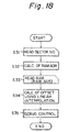
- Fig. 18 is a flowchart of the operations for the head positioning control, with an offset correction at the time of a read or write using the mean offset obtained through the averaging calculation by the operations in Fig. 15, which are stored in the RAM.
- This control is featured by the fact that the offset for each sector is restored by linear interpolation using the mean offset.
- the number for a to-be-accessed sector is read in.
- Offset of the to-be-accessed sector is calculated by linear interpolation.
- a servo control is effected with an offset correction in which the head is moved to eliminate the offset restored during the seeking of a designated sector in a designated cylinder.
- the sector number is normalized to a common value every four sectors.
- a linear interpolation is effected using a gradient K1 of a straight line obtained from the contents RAM[RAM ADR] at a RAM address in consideration and those RAM[RAM ADR - 1] at the preceding RAM address.
- K1 (RAM[RAM ADR] - RAM[RAM ADR - 1])/4
- K2 (RAM[RAM ADR + 1] - RAM[RAM ADR])/4
- an offtrack value OFFSET[SECTOR] indicated with a linear-interpolated Q point of the to-be-accessed sector can be calculated by determining a difference (D) between the remainder 1.5 at the central position and the remainder, for example, 1 being a to-be-accessed sector position to be (MOD(SECTOR, 4) - 1.5), multiplying this difference by the gradient K1 (alternately K2 when the remainder of the to-be-accessed sector is 2, 3) and adding the value at the P point to the result of the multiplication.
- Fig. 21 shows an offset restored from the contents stored in RAM shown in Fig. 17 by linear interpolation.
- the raw data shown in Fig. 17 can be sufficiently fitted.
- Fig. 22 shows a head positioning servo control with an offtrack correction (offset correction) at step S35 in Fig. 18.
- an offset correction may be done during ontrack after completion of a seek.
- an offset correction may be done at the start of a seek to position the head over an object sector by a seeking operation. By the offtrack correction at the start of a seek as shown at (102), it is possible to reduce the time until the head is ontrack.
- the servo surface is provided on one of the plurality of disks that is located at either the highest or lowest position, but it may also be provided on a disk at an appropriate position such as a middle position.
- the magnetic disk unit of this embodiment has an offset detecting mode executed by the data head offset detecting circuit and a data write or read mode, in which the data head writes or reads data onto or from the data surface of the disk data medium, is executed; when the unit has executed the offset detecting mode, the data write or read mode also may interrupt the offset detecting mode.
- the servo head 34 and data heads 2 are mechanically coupled to each other. Therefore, the vibrations applied to both these data and servo heads are of the same magnitude.
- embodiments of the present invention can permit more accurate detection of an offset by eliminating or significantly reducing errors due to vibration even if the offset detection is done while the head is oscillating due to external vibration and can considerably improve the accuracy of head positioning control with an offset correction using the servo information on the servo and data surfaces.
Landscapes
- Moving Of The Head To Find And Align With The Track (AREA)
Claims (8)
- Circuit de détection de décalage de têtes de données pour une unité d'entraînement de disques magnétiques incluant une surface d'asservissement constituant un disque support de données (1), une tête d'asservissement (34) prévue en face de la surface d'asservissement, une pluralité de surfaces de données constituant des disques supports de données (1) qui stockent des données, et une pluralité de têtes de données (2) prévues en face des surfaces de données, respectivement, pour corriger un décalage des têtes de données (2) par utilisation d'informations d'asservissement sur la surface d'asservissement et d'informations d'asservissement sur les surfaces de données, où ledit circuit comprend un premier moyen de détection de décalage (3) pour détecter une valeur de décalage (β) des têtes de données (2) selon les informations d'asservissement lues par les têtes de données (2) sur les surfaces de données ;
caractérisé en ce que ledit circuit comprend en outre :un second moyen de détection de décalage (4) pour détecter une valeur de décalage (γ) d'une tête d'asservissement (34) selon les informations d'asservissement lues par la tête d'asservissement (34) sur la surface d'asservissement, et,un moyen de calcul de décalage (5) pour calculer une vraie valeur de décalage (α) en retranchant la valeur de décalage (γ) détectée par le second moyen de détection de décalage (4) de la valeur de décalage (β) détectée par le premier moyen de détection de décalage (3). - Circuit de détection de décalage de têtes de données selon la revendication 1, dans lequel des premières informations d'asservissement (A) décalées d'une quantité constante vers l'extérieur par rapport à la position sur piste et des secondes informations d'asservissement (B) décalées de la quantité constante vers l'intérieur par rapport à la position sur piste sont enregistrées pour chaque secteur comme informations d'asservissement sur les surfaces de données.
- Circuit de détection de décalage de têtes de données selon la revendication 2, dans lequel ledit premier moyen de détection de décalage (3) calcule un signal indicatif d'une différence (VA - VB) entre les premières informations d'asservissement (A) et les secondes informations d'asservissement (B) lues par les têtes de données (2) sur la surface de données et multiplie la différence (VA - VB) par un coefficient constant de proportionnalité (K) pour détecter le décalage (β).
- Circuit de détection de décalage de têtes de données selon la revendication 1, comprenant en outre une mémoire de décalages (6) mettant en oeuvre une mémoire RAM qui stocke pour chacune desdites têtes de données (2) la valeur de décalage (α) calculée par ledit moyen de calcul de décalage (5).
- Circuit de détection de décalage de têtes de données selon la revendication 4, dans lequel les informations d'asservissement sur lesdites surfaces de données sont enregistrées pour chaque secteur, et des décalages (α1 à αn) détectés pour chaque secteur sont calculés en moyenne par nombre prédéterminé de secteurs (N) et stockés dans la mémoire RAM, qui compose la mémoire de décalages (6).
- Circuit de détection de décalage de têtes de données selon la revendication 5, comprenant en outre un contrôleur de positionnement (7) pour obtenir une correction de décalage au moment d'une lecture ou d'une écriture par lesdites têtes de données (2) sur les surfaces de données par la lecture d'une valeur moyenne de décalage pour un secteur auquel on doit accéder et un secteur juste avant et après lesdites valeurs moyennes de décalage, et déterminer un décalage pour ledit secteur auquel on doit accéder par une interpolation linéaire.
- Unité d'entraînement de disques magnétiques mettant en oeuvre un circuit de détection de décalage de têtes de données selon la revendication 1.
- Unité d'entraînement de disques magnétiques selon la revendication 7, où ladite unité a un mode de détection de décalage exécuté par le circuit de détection de décalage de têtes de données et où un mode d'écriture ou de lecture de données, dans lequel la tête de données (2) écrit ou lit des données sur la surface de données du disque support de données, est exécuté, et, quand l'unité a exécuté le mode de détection de décalage, le mode d'écriture ou de lecture de données interrompt le mode de détection de décalage.
Applications Claiming Priority (2)
| Application Number | Priority Date | Filing Date | Title |
|---|---|---|---|
| JP98508/91 | 1991-04-30 | ||
| JP3098508A JP2653933B2 (ja) | 1991-04-30 | 1991-04-30 | 磁気ディスク装置のオフセット検出方式 |
Publications (3)
| Publication Number | Publication Date |
|---|---|
| EP0511863A2 EP0511863A2 (fr) | 1992-11-04 |
| EP0511863A3 EP0511863A3 (en) | 1993-02-10 |
| EP0511863B1 true EP0511863B1 (fr) | 1997-10-08 |
Family
ID=14221591
Family Applications (1)
| Application Number | Title | Priority Date | Filing Date |
|---|---|---|---|
| EP92303908A Expired - Lifetime EP0511863B1 (fr) | 1991-04-30 | 1992-04-30 | Unité d'entraînement de disque magnétique |
Country Status (5)
| Country | Link |
|---|---|
| US (1) | US5321564A (fr) |
| EP (1) | EP0511863B1 (fr) |
| JP (1) | JP2653933B2 (fr) |
| KR (1) | KR960006334B1 (fr) |
| DE (1) | DE69222563T2 (fr) |
Families Citing this family (23)
| Publication number | Priority date | Publication date | Assignee | Title |
|---|---|---|---|---|
| JP2644182B2 (ja) * | 1993-06-14 | 1997-08-25 | インターナショナル・ビジネス・マシーンズ・コーポレイション | 多重トラック磁気テープ装置を初期化する装置及び方法 |
| US5500776A (en) * | 1993-12-16 | 1996-03-19 | Seagate Technology, Inc. | Self-calibration for computer disk read/write offsets |
| JPH07254242A (ja) * | 1994-03-16 | 1995-10-03 | Hitachi Ltd | ヘッド切り換え制御装置 |
| KR0147228B1 (ko) * | 1994-10-27 | 1998-10-15 | 김광호 | 자기 디스크 구동장치에서 오프-트랙을 이용한 트랙 추종 방법 |
| KR100224918B1 (ko) | 1995-09-06 | 1999-10-15 | 윤종용 | 디스크 기록면들의 트랙오프셋에 의한 헤드간 트랙위치 오프셋 보상장치 및 그 방법 |
| CA2225919A1 (fr) * | 1996-04-26 | 1997-11-06 | Jordi Llado Abella | Systeme et procede de marquage ou de perforation |
| US6351342B1 (en) * | 1996-05-24 | 2002-02-26 | Seagate Technology Llc | Disc drive servo system with dual head sampling |
| US6208480B1 (en) | 1997-10-16 | 2001-03-27 | Seagate Technology Llc | Circuit and method for maintaining a rotation position reference on a disc drive with a staggered servo format |
| US6388413B1 (en) | 1999-01-15 | 2002-05-14 | Seagate Technology Llc | Head switch seek on disc drives with multiple recording heads |
| US6538835B1 (en) | 1999-02-22 | 2003-03-25 | Seagate Technology Llc | Position signal distortion compensation during a disc drive seek |
| US6510015B2 (en) | 1999-12-10 | 2003-01-21 | Seagate Technology Llc | Magnetic disc having physical servo patterns with a magnetic carrier, and method of making and using the same |
| US7193812B2 (en) * | 2003-07-25 | 2007-03-20 | International Business Machines Corporation | Recording head compensation for tape shrinkage and expansion |
| KR100585164B1 (ko) | 2004-11-30 | 2006-06-01 | 삼성전자주식회사 | 레퍼런스 서보 트랙 카피 시스템에서의 트랙 제로 위치보정 방법 및 이를 이용한 디스크 드라이브 |
| US8792200B1 (en) * | 2013-09-23 | 2014-07-29 | Western Digital Technologies, Inc. | Disk drive employing a temperature dependent write offset |
| US10014026B1 (en) | 2017-06-20 | 2018-07-03 | Seagate Technology Llc | Head delay calibration and tracking in MSMR systems |
| US10297281B1 (en) | 2017-11-06 | 2019-05-21 | Seagate Technology Llc | Servo sector detection |
| US11016681B1 (en) | 2018-07-31 | 2021-05-25 | Seagate Technology Llc | Multi-threshold parameter adaptation |
| US10522177B1 (en) | 2018-07-31 | 2019-12-31 | Seagate Technology Llc | Disc locked clock-based servo timing |
| US11018842B1 (en) | 2018-07-31 | 2021-05-25 | Seagate Technology Llc | Dynamic timing recovery bandwidth modulation for phase offset mitigation |
| US10803902B1 (en) | 2018-08-19 | 2020-10-13 | Seagate Technology Llc | Hardware-based read sample averaging |
| US10460762B1 (en) | 2018-09-04 | 2019-10-29 | Seagate Technology Llc | Cancelling adjacent track interference signal with different data rate |
| US10468060B1 (en) | 2018-09-27 | 2019-11-05 | Seagate Technology Llc | Cancelling adjacent track interference |
| US10783911B1 (en) * | 2020-02-24 | 2020-09-22 | Western Digital Technologies, Inc. | Data storage device bank writing servo sectors for interleaved servo control processing |
Family Cites Families (11)
| Publication number | Priority date | Publication date | Assignee | Title |
|---|---|---|---|---|
| JPS5419718A (en) * | 1977-07-14 | 1979-02-14 | Hitachi Ltd | Locating system of high accuracy |
| JPS56134366A (en) * | 1980-02-14 | 1981-10-21 | Mitsubishi Electric Corp | Disk device |
| US5023733A (en) * | 1985-12-16 | 1991-06-11 | Seiko Epson Corporation | Head positioning control for a spindle motor disk drive |
| JPS6363184A (ja) * | 1986-09-02 | 1988-03-19 | Seiko Epson Corp | 磁気記録装置 |
| AU8091887A (en) * | 1986-11-10 | 1988-05-12 | Seagate Technology, Inc. | Dual track servo system |
| JPS63244382A (ja) * | 1987-03-31 | 1988-10-11 | Toshiba Corp | 磁気デイスク装置 |
| JPS63273284A (ja) * | 1987-04-30 | 1988-11-10 | Toshiba Corp | 磁気記録再生装置のサ−ボ方式 |
| JPH0192971A (ja) * | 1987-10-05 | 1989-04-12 | Hitachi Ltd | 磁気ディスク装置のヘッド位置決め機構 |
| JPH01264674A (ja) * | 1988-04-15 | 1989-10-20 | Hitachi Ltd | サーボ制御方法およびその装置 |
| JPH02220262A (ja) * | 1989-02-20 | 1990-09-03 | Fujitsu Ltd | ディスク装置のヘッド切替方式 |
| JPH0337875A (ja) * | 1989-07-04 | 1991-02-19 | Toshiba Corp | データ記録再生装置のヘッド駆動制御装置 |
-
1991
- 1991-04-30 JP JP3098508A patent/JP2653933B2/ja not_active Expired - Fee Related
-
1992
- 1992-04-28 US US07/875,080 patent/US5321564A/en not_active Expired - Lifetime
- 1992-04-30 DE DE69222563T patent/DE69222563T2/de not_active Expired - Fee Related
- 1992-04-30 KR KR1019920007365A patent/KR960006334B1/ko not_active Expired - Fee Related
- 1992-04-30 EP EP92303908A patent/EP0511863B1/fr not_active Expired - Lifetime
Also Published As
| Publication number | Publication date |
|---|---|
| EP0511863A2 (fr) | 1992-11-04 |
| US5321564A (en) | 1994-06-14 |
| KR960006334B1 (ko) | 1996-05-13 |
| DE69222563T2 (de) | 1998-02-12 |
| DE69222563D1 (de) | 1997-11-13 |
| KR920020409A (ko) | 1992-11-21 |
| JP2653933B2 (ja) | 1997-09-17 |
| JPH05189902A (ja) | 1993-07-30 |
| EP0511863A3 (en) | 1993-02-10 |
Similar Documents
| Publication | Publication Date | Title |
|---|---|---|
| EP0511863B1 (fr) | Unité d'entraînement de disque magnétique | |
| US7123433B1 (en) | Method and apparatus for runout correction during self-servo writing | |
| US5072318A (en) | Disk file with adaptive cancellation of nonrepeatable disk runout | |
| KR0160001B1 (ko) | 헤드의 판독 소자 및 기록 소자간 간격 결정 방법과 데이타 배치시의 조직적 에러 정정 방법 및 자기 서보 기록 방법 | |
| EP0494869B1 (fr) | Systeme d'unite de disques utilisant de multiples champs de quadrature d'asservissement encastres | |
| US5444583A (en) | Disk drive having on-board triggered digital sampling analyzer | |
| US7869156B2 (en) | Method of creating correction table for head position control, head position control method, and disk device | |
| JP4106487B2 (ja) | 位置決め制御装置 | |
| US6989956B2 (en) | Head position control method, disk device, and servo track write method | |
| US7623313B1 (en) | Method and apparatus for performing a self-servo write operation in a disk drive | |
| EP0308070B1 (fr) | Fichier à guide d'enregistrement de données avec commande d'asservissement numérique | |
| JPS62277669A (ja) | デイスク記憶装置のヘツド位置制御方式 | |
| US6865051B2 (en) | Head position control method and disk storage device | |
| EP0511862B1 (fr) | Unité de disque magnétique | |
| JPH0945025A (ja) | ディスク装置およびヘッド間ずれ量計測方法 | |
| JPH0991903A (ja) | ディスク記録再生装置のヘッド位置決め制御装置及びそのヘッド位置決め制御方法 | |
| JP3321295B2 (ja) | ディスク装置 | |
| JP2611054B2 (ja) | 磁気ディスク装置のデータ面サーボ信号検出感度の補正方式 | |
| JP3718158B2 (ja) | ディスク装置 | |
| KR960012892B1 (ko) | 자기디스크장치의 데이타 헤드의 오프셋 측정회로 | |
| JPH03108167A (ja) | データ面サーボ制御方式のディスク装置 | |
| JP3781029B2 (ja) | ディスク装置 | |
| JPH04364277A (ja) | 磁気ディスク装置のオフセット検出方式 | |
| JPH04103084A (ja) | データ記録再生装置のヘッド位置決め制御装置 | |
| JPH05210924A (ja) | 磁気ディスク装置におけるヘッドの位置ずれ検出装置および検出方法 |
Legal Events
| Date | Code | Title | Description |
|---|---|---|---|
| PUAI | Public reference made under article 153(3) epc to a published international application that has entered the european phase |
Free format text: ORIGINAL CODE: 0009012 |
|
| AK | Designated contracting states |
Kind code of ref document: A2 Designated state(s): DE FR GB |
|
| PUAL | Search report despatched |
Free format text: ORIGINAL CODE: 0009013 |
|
| AK | Designated contracting states |
Kind code of ref document: A3 Designated state(s): DE FR GB |
|
| 17P | Request for examination filed |
Effective date: 19930616 |
|
| 17Q | First examination report despatched |
Effective date: 19950728 |
|
| GRAG | Despatch of communication of intention to grant |
Free format text: ORIGINAL CODE: EPIDOS AGRA |
|
| GRAH | Despatch of communication of intention to grant a patent |
Free format text: ORIGINAL CODE: EPIDOS IGRA |
|
| GRAH | Despatch of communication of intention to grant a patent |
Free format text: ORIGINAL CODE: EPIDOS IGRA |
|
| GRAA | (expected) grant |
Free format text: ORIGINAL CODE: 0009210 |
|
| AK | Designated contracting states |
Kind code of ref document: B1 Designated state(s): DE FR GB |
|
| REF | Corresponds to: |
Ref document number: 69222563 Country of ref document: DE Date of ref document: 19971113 |
|
| ET | Fr: translation filed | ||
| PLBE | No opposition filed within time limit |
Free format text: ORIGINAL CODE: 0009261 |
|
| STAA | Information on the status of an ep patent application or granted ep patent |
Free format text: STATUS: NO OPPOSITION FILED WITHIN TIME LIMIT |
|
| 26N | No opposition filed | ||
| REG | Reference to a national code |
Ref country code: GB Ref legal event code: IF02 |
|
| PGFP | Annual fee paid to national office [announced via postgrant information from national office to epo] |
Ref country code: FR Payment date: 20080312 Year of fee payment: 17 Ref country code: DE Payment date: 20080508 Year of fee payment: 17 |
|
| PGFP | Annual fee paid to national office [announced via postgrant information from national office to epo] |
Ref country code: GB Payment date: 20080430 Year of fee payment: 17 |
|
| GBPC | Gb: european patent ceased through non-payment of renewal fee |
Effective date: 20090430 |
|
| REG | Reference to a national code |
Ref country code: FR Ref legal event code: ST Effective date: 20091231 |
|
| PG25 | Lapsed in a contracting state [announced via postgrant information from national office to epo] |
Ref country code: DE Free format text: LAPSE BECAUSE OF NON-PAYMENT OF DUE FEES Effective date: 20091103 |
|
| PG25 | Lapsed in a contracting state [announced via postgrant information from national office to epo] |
Ref country code: FR Free format text: LAPSE BECAUSE OF NON-PAYMENT OF DUE FEES Effective date: 20091222 Ref country code: GB Free format text: LAPSE BECAUSE OF NON-PAYMENT OF DUE FEES Effective date: 20090430 |