EP0512906B1 - Nickel-Wasserstoff Akkumulatorenbatterie - Google Patents
Nickel-Wasserstoff Akkumulatorenbatterie Download PDFInfo
- Publication number
- EP0512906B1 EP0512906B1 EP92401243A EP92401243A EP0512906B1 EP 0512906 B1 EP0512906 B1 EP 0512906B1 EP 92401243 A EP92401243 A EP 92401243A EP 92401243 A EP92401243 A EP 92401243A EP 0512906 B1 EP0512906 B1 EP 0512906B1
- Authority
- EP
- European Patent Office
- Prior art keywords
- battery
- corset
- storage cells
- battery according
- baseplate
- Prior art date
- Legal status (The legal status is an assumption and is not a legal conclusion. Google has not performed a legal analysis and makes no representation as to the accuracy of the status listed.)
- Expired - Lifetime
Links
Images


Classifications
-
- B—PERFORMING OPERATIONS; TRANSPORTING
- B64—AIRCRAFT; AVIATION; COSMONAUTICS
- B64G—COSMONAUTICS; VEHICLES OR EQUIPMENT THEREFOR
- B64G1/00—Cosmonautic vehicles
- B64G1/22—Parts of, or equipment specially adapted for fitting in or to, cosmonautic vehicles
- B64G1/42—Arrangements or adaptations of power supply systems
- B64G1/425—Power storage
-
- H—ELECTRICITY
- H01—ELECTRIC ELEMENTS
- H01M—PROCESSES OR MEANS, e.g. BATTERIES, FOR THE DIRECT CONVERSION OF CHEMICAL ENERGY INTO ELECTRICAL ENERGY
- H01M50/00—Constructional details or processes of manufacture of the non-active parts of electrochemical cells other than fuel cells, e.g. hybrid cells
- H01M50/20—Mountings; Secondary casings or frames; Racks, modules or packs; Suspension devices; Shock absorbers; Transport or carrying devices; Holders
- H01M50/204—Racks, modules or packs for multiple batteries or multiple cells
- H01M50/207—Racks, modules or packs for multiple batteries or multiple cells characterised by their shape
- H01M50/213—Racks, modules or packs for multiple batteries or multiple cells characterised by their shape adapted for cells having curved cross-section, e.g. round or elliptic
-
- Y—GENERAL TAGGING OF NEW TECHNOLOGICAL DEVELOPMENTS; GENERAL TAGGING OF CROSS-SECTIONAL TECHNOLOGIES SPANNING OVER SEVERAL SECTIONS OF THE IPC; TECHNICAL SUBJECTS COVERED BY FORMER USPC CROSS-REFERENCE ART COLLECTIONS [XRACs] AND DIGESTS
- Y02—TECHNOLOGIES OR APPLICATIONS FOR MITIGATION OR ADAPTATION AGAINST CLIMATE CHANGE
- Y02E—REDUCTION OF GREENHOUSE GAS [GHG] EMISSIONS, RELATED TO ENERGY GENERATION, TRANSMISSION OR DISTRIBUTION
- Y02E60/00—Enabling technologies; Technologies with a potential or indirect contribution to GHG emissions mitigation
- Y02E60/10—Energy storage using batteries
Definitions
- the present invention relates to a nickel-hydrogen storage battery, in particular for use in spacecraft.
- volume energy and mass energy are two fundamental parameters of a space battery. So during its design we try to minimize its dimensions and lower its weight as much as possible.
- a nickel-hydrogen accumulator battery comprising a base plate which is a sheet 3 to 4 mm thick supporting the accumulators. Each accumulator being placed in a corset provided with a base allowing its fixing on the base plate. If the base is re-entrant, its fixing to the base plate, by screwing or riveting, is done from below the plate. If the base is protruding, it is fixed from above.
- This accumulator battery also comprises electrical protection elements connected to the terminals of the accumulators and arranged either above the accumulators or below.
- the base plate of this battery has a certain flexibility which is compensated by the mechanical cohesion of the entire battery. Indeed, the battery needs enough stiffness to avoid constraining the wall of the satellite which will support it, this wall being honeycomb for reasons of lightness.
- the electrical protection elements being located below or above the accumulators, the mechanical cohesion of the assembly can be ensured in the upper part by glue joints between accumulators or by mechanical clamping elements.
- This storage battery has too high a height due to the installation of the electrical protection elements.
- the present invention aims to overcome this drawback.
- the electrical protection elements are placed between the accumulators and leads to slightly increasing the dimensions in the plane of the battery, but this is not too annoying. It is especially a gain on the height of the battery that we want to obtain.
- Spreading the accumulators no longer ensures the cohesion of the battery by an adhesive joint.
- the base plate a particular configuration which alone ensures the cohesion of the entire battery.
- the subject of the invention is therefore a nickel-hydrogen accumulator battery comprising a base plate supporting the accumulators, each accumulator being held by a corset fixed to the base plate, the battery also comprising electrical protection elements of the accumulators, characterized in that the base plate comprises cells for receiving the corsets, the electrical protection elements being arranged between the accumulators.
- the nickel-hydrogen accumulators used in the space field appear externally in the form of a cylinder terminated at its two ends by a hemisphere.
- One of the half-spheres carries the two electrical terminals and the queusot necessary for the development of the accumulator.
- the accumulators are held in corsets for their attachment to the base plate of the battery.
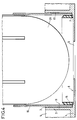
- Figures 1 and 2 are side and top views of the base plate used in the storage battery according to the invention. It is preferably an aluminum plate for reasons of weight.
- the base plate 1 has circular cells 2 hollowed out on the major part of one of its main faces.
- the cells are advantageously provided in a hexagonal arrangement and are practically adjacent for the best space saving possible.
- the plate 1 is also hollowed out of the walls 3 of the cells so as to leave as little material as possible.
- the walls of the cells are connected together, by the shortest route, by solid parts 4.
- These solid parts 4 which may have the same height as the walls 3 of the cells, are of reduced mass so that there are depressions 5 between three adjacent cells.
- the bottom of the cells is thinner than the bottom remaining in other places.
- the bottom of the cells is pierced with a central hole 6 large enough to further lighten the plate.
- the base plate can include still other details of construction not referenced to allow its fixing in a satellite.
- the entry of the cells is chamfered to facilitate the introduction of the corsets holding the accumulators.
- corsets are simple sections of tube with circular section and without any particular base, hence a considerable reduction in the cost of obtaining this part and a reduced size at the sole footprint of the external section thereof.
- the reduced cost is a significant advantage in the case of a spatial application.
- the corsets used in the devices of the known art are of less simple design: they have bases machined to be screwed or riveted, or can be formed from a rolled up sheet and maintained in this state by screwing.
- the corset In addition to its mechanical role, the corset must provide a function of thermal continuity between the accumulators. Indeed, the battery must operate within a very limited range of thermal variation (a few degrees Celsius, for example between 0 and 10 ° C) while the outside temperature, near the battery, can vary between - 25 and + 60 ° vs. In addition, the battery disturbs the thermal atmosphere: it heats up when it delivers energy and it cools down when it charges. There is conventionally on this type of battery a thermal regulation system. Good thermal continuity between the accumulators is therefore necessary. The corset contributes to good thermal continuity by evacuating calories or bringing them as the case may be.
- the accumulators are mounted in their corset before being fixed on the base plate.
- the assembly can be done according to the method illustrated in FIG. 3.
- One side of the corset 10 is closed with a plug II of hollow and hemispherical shape corresponding to the hemisphere ending the corset.
- An O-ring 12 is disposed in a peripheral groove of the plug to seal between the corset and the plug.
- the hemispherical bottom of the stopper is provided with a small pile of glue 13, for example of the resin sold under the brand "Solithane C 113".
- the accumulator 20 is equipped with fine centering strips 21 regularly arranged and glued on the periphery of the cylindrical part of the accumulator and parallel to the axis of the accumulator.
- These strips can be made of a material such as that sold under the brand "Kapton" and be arranged every 60 ° around the axis of the accumulator. They can be 0.1 mm thick.
- the accumulator thus equipped with its strips is designed to be slippery just in the corset. By pushing the accumulator into its corset as shown in Figure 3, it causes the resin to rise in the space separating the corset from the cylindrical part of the accumulator. The hemisphere of the accumulator marrying its counterpart of the cap, all the resin is forced to go up. The plug is then removed and the resin is polymerized. In this way a sheet of bubble-free glue is obtained, which is important for having good thermal conduction between the corset and the accumulator, as well as good electrical insulation.
- corsets are assembled on the base plate by gluing.
- An adhesive film of the order of 0.3 mm thick is placed between the outer skin of the corset in the lower part and the inner skin of the socket of the base plate.
- FIG. 4 The positioning of a corset on the base plate is shown in FIG. 4.
- a centering ring 15 made of space quality plastic is first placed at the bottom of the cell 2. This ring is centered thanks to the heel 7 from the bottom of the cell.
- the ground wire is fixed which must electrically connect the corset to the base plate.
- This ground wire is connected on the one hand to the corset by a countersunk head screw lodged in the hole 14 (see Figure 3) and a nut, on the other hand to the base plate by a screw fixing to the bottom of the socket.
- the attachment points of this ground wire have been symbolically represented: the axis 16 for the corset (this is the axis of the hole 14) and the axis 8 for the base plate.
- the groove existing between the wall 3 of the socket and the ring 15 is filled by means of a syringe.
- the corset is pushed into the socket.
- the inside diameter of the corset is equal, apart from the clearance, to the outside diameter of the ring.
- the glue then rises between the wall 3 of the cell and the corset to form a sheet 17 free of air bubbles.
- the glue can be of the same type as that which was used to stick the accumulator in its corset.
- a small counterbore may be provided to possibly collect an excess of glue.
- the electrical protection elements of the accumulators can be fixed, by means of a small support per accumulator, in the depressions 5 by screwing. The electrical protection elements are then connected by connection wires to the terminals of the accumulators.
- the battery will be fixed to the wall of the satellite by screws passing through the base plate through the holes 9 drilled in certain solid parts 4.
- the depth of a cell can be 29 mm for an internal diameter of 92 mm and a wall thickness of 2 mm.
Landscapes
- Engineering & Computer Science (AREA)
- General Chemical & Material Sciences (AREA)
- Aviation & Aerospace Engineering (AREA)
- Chemical & Material Sciences (AREA)
- Chemical Kinetics & Catalysis (AREA)
- Electrochemistry (AREA)
- Remote Sensing (AREA)
- Battery Mounting, Suspending (AREA)
- Secondary Cells (AREA)
- Battery Electrode And Active Subsutance (AREA)
- Organic Low-Molecular-Weight Compounds And Preparation Thereof (AREA)
- Hybrid Cells (AREA)
- Sealing Battery Cases Or Jackets (AREA)
Claims (9)
- Nickel-Wasserstoff-Akkumulatorenbatterie, die eine die Akkumulatoren tragende Basisplatte aufweist, wobei jeder Akkumulator von einer an der Basisplatte befestigten Manschette gehalten wird und wobei die Batterie weiter elektrische Schutzelemente für die der Akkumulatoren aufweist, dadurch gekennzeichnet, daß die Basisplatte (1) Zellen (2) zur Aufnahme der Manschetten (10) aufweist, wobei die elektrischen Schutzelemente zwischen den Akkumulatoren (20) angeordnet sind.
- Batterie nach Anspruch 1, dadurch gekennzeichnet, daß die Zellen (2) im Sechseck angeordnet sind.
- Batterie nach einem der Ansprüche 1 und 2, dadurch gekennzeichnet, daß der Boden der Zellen (2) ein Loch aufweist.
- Batterie nach einem beliebigen der Ansprüche 1 bis 3, dadurch gekennzeichnet, daß die Zellen (2) miteinander durch massive Bereiche (4) verbunden sind.
- Batterie nach einem beliebigen der Ansprüche 1 bis 4, dadurch gekennzeichnet, daß die elektrischen Schutzelemente in Vertiefungen (5) der Basisplatte angeordnet sind, die sich zwischen den Zellen (2) befinden.
- Batterie nach einem beliebigen der Ansprüche 1 bis 5, dadurch gekennzeichnet, daß die Manschetten (10) einfache Rohrabschnitte sind.
- Batterie nach einem beliebigen der Ansprüche 1 bis 6, dadurch gekennzeichnet, daß die Akkumulatoren (20) in ihren Manschetten durch eine Kleberschicht gehalten werden.
- Batterie nach einem beliebigen der Ansprüche 1 bis 6, dadurch gekennzeichnet, daß die Manschetten (10) in den Zellen (2) durch eine Kleberschicht (17) gehalten werden.
- Batterie nach einem beliebigen der vorhergehenden Ansprüche, dadurch gekennzeichnet, daß jede Manschette (10) in ihrer Zelle (2) mittels eines Rings (15) zentriert wird.
Applications Claiming Priority (2)
| Application Number | Priority Date | Filing Date | Title |
|---|---|---|---|
| FR9105461 | 1991-05-03 | ||
| FR9105461A FR2676144B1 (fr) | 1991-05-03 | 1991-05-03 | Batterie d'accumulateurs nickel-hydrogene. |
Publications (2)
| Publication Number | Publication Date |
|---|---|
| EP0512906A1 EP0512906A1 (de) | 1992-11-11 |
| EP0512906B1 true EP0512906B1 (de) | 1995-07-05 |
Family
ID=9412498
Family Applications (1)
| Application Number | Title | Priority Date | Filing Date |
|---|---|---|---|
| EP92401243A Expired - Lifetime EP0512906B1 (de) | 1991-05-03 | 1992-04-30 | Nickel-Wasserstoff Akkumulatorenbatterie |
Country Status (7)
| Country | Link |
|---|---|
| US (1) | US5268242A (de) |
| EP (1) | EP0512906B1 (de) |
| JP (1) | JPH05508256A (de) |
| AT (1) | ATE124807T1 (de) |
| DE (1) | DE69203289T2 (de) |
| FR (1) | FR2676144B1 (de) |
| WO (1) | WO1992020113A1 (de) |
Families Citing this family (16)
| Publication number | Priority date | Publication date | Assignee | Title |
|---|---|---|---|---|
| FR2710899B1 (fr) * | 1993-10-08 | 1995-12-15 | Matra Marconi Space France | Satellite géostationnaire à accumulateurs d'énergie électrique. |
| US5510208A (en) * | 1994-09-28 | 1996-04-23 | Space Systems/Loral, Inc. | Composite battery cell sleeve |
| US5763116A (en) * | 1997-02-12 | 1998-06-09 | Mcdonnell Douglas Corporation | Nickel hydrogen battery apparatus |
| FR2774513A1 (fr) * | 1998-02-04 | 1999-07-30 | Loral Space Systems Inc | Manchon d'element de batterie pour applications spatiales et son procede de fabrication |
| US6238820B1 (en) | 1998-02-04 | 2001-05-29 | Space Systems/Loral, Inc. | Battery cell sleeve for spacecraft applications |
| US6207315B1 (en) | 1998-06-15 | 2001-03-27 | Space Systems/Loral, Inc. | Three dimensional battery for space applications |
| US7189473B2 (en) | 2003-06-03 | 2007-03-13 | Eastway Fair Company Limited | Battery venting system |
| RU2316085C1 (ru) * | 2006-04-07 | 2008-01-27 | Открытое акционерное общество "Сатурн" | Никель-водородная аккумуляторная батарея |
| DE102006025535A1 (de) * | 2006-06-01 | 2007-12-06 | Behr Gmbh & Co. Kg | Vorrichtung zur Kühlung elektrischer Elemente |
| DE102006045564A1 (de) * | 2006-09-25 | 2008-04-03 | Behr Gmbh & Co. Kg | Vorrichtung zur Kühlung elektrischer Elemente |
| FR2929760B1 (fr) * | 2008-04-08 | 2010-10-01 | Vehicules Electr Soc D | Batterie electrique comprenant des elements generateurs souples et un systeme de conditionnement mecanique et thermique desdits elements |
| DE102008023945A1 (de) | 2008-05-16 | 2009-11-19 | Evgueni, Levotmann | Das Verfahren der Wärmeumwandlung in die Elektroenergie |
| RU2368984C1 (ru) * | 2008-07-09 | 2009-09-27 | Открытое акционерное общество "Сатурн" | Никель-водородная аккумуляторная батарея |
| RU2390885C1 (ru) * | 2008-12-22 | 2010-05-27 | Государственное образовательное учреждение высшего профессионального образования "Сибирский государственный аэрокосмический университет имени академика М.Ф. Решетнева" (СибГАУ) | Аккумуляторная батарея космического аппарата |
| RU2386196C1 (ru) * | 2009-03-02 | 2010-04-10 | Открытое акционерное общество "Сатурн" | Никель-водородная аккумуляторная батарея |
| CN103786905B (zh) * | 2014-01-02 | 2015-06-10 | 北京空间飞行器总体设计部 | 一种能够适应气瓶双向变形的支撑紧固装置 |
Family Cites Families (6)
| Publication number | Priority date | Publication date | Assignee | Title |
|---|---|---|---|---|
| US1606391A (en) * | 1925-01-02 | 1926-11-09 | Burgess Battery Co | Dry battery |
| US2209927A (en) * | 1937-04-20 | 1940-07-30 | Nat Carbon Co Inc | Dry battery construction |
| US3178317A (en) * | 1962-09-26 | 1965-04-13 | Maddaloni John Baptist | Dry cell power supply |
| US4420545A (en) * | 1981-11-05 | 1983-12-13 | Ford Aerospace & Communications Corporation | Lightweight metal-gas battery |
| GB8715708D0 (en) * | 1987-07-03 | 1987-08-12 | Chloride Silent Power Ltd | Batteries |
| DE8815962U1 (de) * | 1988-12-23 | 1989-02-16 | Licentia Patent-Verwaltungs-Gmbh, 6000 Frankfurt | Gehäuse für Batterien |
-
1991
- 1991-05-03 FR FR9105461A patent/FR2676144B1/fr not_active Expired - Fee Related
-
1992
- 1992-04-30 AT AT92401243T patent/ATE124807T1/de not_active IP Right Cessation
- 1992-04-30 EP EP92401243A patent/EP0512906B1/de not_active Expired - Lifetime
- 1992-04-30 DE DE69203289T patent/DE69203289T2/de not_active Expired - Fee Related
- 1992-04-30 WO PCT/FR1992/000395 patent/WO1992020113A1/fr not_active Ceased
- 1992-04-30 JP JP92509834A patent/JPH05508256A/ja active Pending
- 1992-05-01 US US07/877,108 patent/US5268242A/en not_active Expired - Fee Related
Also Published As
| Publication number | Publication date |
|---|---|
| US5268242A (en) | 1993-12-07 |
| JPH05508256A (ja) | 1993-11-18 |
| ATE124807T1 (de) | 1995-07-15 |
| EP0512906A1 (de) | 1992-11-11 |
| WO1992020113A1 (fr) | 1992-11-12 |
| DE69203289T2 (de) | 1995-11-02 |
| FR2676144A1 (fr) | 1992-11-06 |
| FR2676144B1 (fr) | 1993-07-16 |
| DE69203289D1 (de) | 1995-08-10 |
Similar Documents
| Publication | Publication Date | Title |
|---|---|---|
| EP0512906B1 (de) | Nickel-Wasserstoff Akkumulatorenbatterie | |
| EP0589804B1 (de) | Elektrisches Gehäuse mit abgedichteter Durchführung für Speisekabel | |
| CA3099206A1 (fr) | Procede d'assemblage d'une batterie | |
| EP2546614B1 (de) | Sensor- oder Detektorvorrichtung mit einem perfektionierten Kabelführungsstöpsel | |
| EP2810286B1 (de) | Abstandhalter, energiespeichermodul,und ihr herstellungsverfahren | |
| FR2689319A1 (fr) | Electrode bipolaire pour batterie d'accumulateurs. | |
| EP3177121B1 (de) | Elektrische vorrichtung und verfahren zum zusammenbau einer solchen elektrischen vorrichtung | |
| WO2018100411A1 (fr) | Dispositif de connexion électrique d'installation photovoltaïque | |
| EP1860672A1 (de) | Stangenbuchsenanordnung, die durch eine Öffnung einer Wand eines Stromwandlers eingebaut werden soll | |
| FR2553894A1 (fr) | Procede et circuit pour le controle de la charge de piles au ni-cd | |
| FR3148872A1 (fr) | Connecteur | |
| EP1349280A1 (de) | Wasserdichtes Anwesenheitssensorsystem, insbesondere für Türgriffe | |
| EP3948905A1 (de) | Kapazitiver block mit einem abstandshalter | |
| EP0076735A1 (de) | Apparat zum Aufbringen von wärmeschmelzbarem Leim | |
| EP2461077B1 (de) | Befestigungsschelle für Rohre | |
| EP4051521A1 (de) | Pumpenträger für eine elektrische oder hybride kraftfahrzeugarchitektur | |
| CA2033368C (fr) | Ensemble permettant une liaison electrique a travers une conduite formee de plusieurs elements | |
| EP1638789B1 (de) | Elektrische verbindungsvorrichtung zwischen einem rad und einer kugellager-nabeanordnung | |
| EP0680109A1 (de) | Antennenfuss mit einer Mutter, die von einer Basis gehalten wird, die nur eine Montagerichtung erlaubt | |
| FR2745958A1 (fr) | Dispositif d'alimentation electrique d'un appareil a alimentation exterieure, fixe sur un support portable | |
| EP1378975B1 (de) | In einem Sachlloch einsetzbare elektrische Verbindungseinrichtung | |
| FR2801430A1 (fr) | Borne electrique etanche avec systeme de blocage en rotation | |
| FR2754646A1 (fr) | Dispositif pour la fixation a un moyen d'alimentation en electricite et la connexion electrique d'une douille pour ampoule electrique | |
| EP2990723B1 (de) | Beleuchtungsvorrichtung, die eine verbesserte halterung umfasst | |
| EP0638760B1 (de) | Elektrische Kerze |
Legal Events
| Date | Code | Title | Description |
|---|---|---|---|
| PUAI | Public reference made under article 153(3) epc to a published international application that has entered the european phase |
Free format text: ORIGINAL CODE: 0009012 |
|
| AK | Designated contracting states |
Kind code of ref document: A1 Designated state(s): AT BE CH DE DK ES FR GB GR IT LI LU MC NL PT SE |
|
| 17P | Request for examination filed |
Effective date: 19930503 |
|
| 17Q | First examination report despatched |
Effective date: 19941111 |
|
| GRAA | (expected) grant |
Free format text: ORIGINAL CODE: 0009210 |
|
| AK | Designated contracting states |
Kind code of ref document: B1 Designated state(s): AT BE CH DE DK ES FR GB GR IT LI LU MC NL PT SE |
|
| PG25 | Lapsed in a contracting state [announced via postgrant information from national office to epo] |
Ref country code: MC Free format text: LAPSE BECAUSE OF NON-PAYMENT OF DUE FEES Effective date: 19950705 Ref country code: GR Free format text: LAPSE BECAUSE OF FAILURE TO SUBMIT A TRANSLATION OF THE DESCRIPTION OR TO PAY THE FEE WITHIN THE PRESCRIBED TIME-LIMIT Effective date: 19950705 Ref country code: ES Free format text: THE PATENT HAS BEEN ANNULLED BY A DECISION OF A NATIONAL AUTHORITY Effective date: 19950705 Ref country code: DK Effective date: 19950705 Ref country code: AT Effective date: 19950705 |
|
| REF | Corresponds to: |
Ref document number: 124807 Country of ref document: AT Date of ref document: 19950715 Kind code of ref document: T |
|
| REF | Corresponds to: |
Ref document number: 69203289 Country of ref document: DE Date of ref document: 19950810 |
|
| ITF | It: translation for a ep patent filed | ||
| PG25 | Lapsed in a contracting state [announced via postgrant information from national office to epo] |
Ref country code: SE Effective date: 19951005 |
|
| PG25 | Lapsed in a contracting state [announced via postgrant information from national office to epo] |
Ref country code: PT Effective date: 19951006 |
|
| GBT | Gb: translation of ep patent filed (gb section 77(6)(a)/1977) |
Effective date: 19950908 |
|
| PG25 | Lapsed in a contracting state [announced via postgrant information from national office to epo] |
Ref country code: LU Free format text: LAPSE BECAUSE OF NON-PAYMENT OF DUE FEES Effective date: 19960430 Ref country code: LI Effective date: 19960430 Ref country code: CH Effective date: 19960430 Ref country code: BE Effective date: 19960430 |
|
| PLBE | No opposition filed within time limit |
Free format text: ORIGINAL CODE: 0009261 |
|
| STAA | Information on the status of an ep patent application or granted ep patent |
Free format text: STATUS: NO OPPOSITION FILED WITHIN TIME LIMIT |
|
| 26N | No opposition filed | ||
| BERE | Be: lapsed |
Owner name: SAFT Effective date: 19960430 |
|
| REG | Reference to a national code |
Ref country code: CH Ref legal event code: PL |
|
| PGFP | Annual fee paid to national office [announced via postgrant information from national office to epo] |
Ref country code: GB Payment date: 19980312 Year of fee payment: 7 |
|
| PGFP | Annual fee paid to national office [announced via postgrant information from national office to epo] |
Ref country code: FR Payment date: 19980313 Year of fee payment: 7 |
|
| PGFP | Annual fee paid to national office [announced via postgrant information from national office to epo] |
Ref country code: DE Payment date: 19980318 Year of fee payment: 7 |
|
| PGFP | Annual fee paid to national office [announced via postgrant information from national office to epo] |
Ref country code: NL Payment date: 19980320 Year of fee payment: 7 |
|
| PG25 | Lapsed in a contracting state [announced via postgrant information from national office to epo] |
Ref country code: GB Free format text: LAPSE BECAUSE OF NON-PAYMENT OF DUE FEES Effective date: 19990430 |
|
| PG25 | Lapsed in a contracting state [announced via postgrant information from national office to epo] |
Ref country code: NL Free format text: LAPSE BECAUSE OF NON-PAYMENT OF DUE FEES Effective date: 19991101 |
|
| GBPC | Gb: european patent ceased through non-payment of renewal fee |
Effective date: 19990430 |
|
| PG25 | Lapsed in a contracting state [announced via postgrant information from national office to epo] |
Ref country code: FR Free format text: LAPSE BECAUSE OF NON-PAYMENT OF DUE FEES Effective date: 19991231 |
|
| NLV4 | Nl: lapsed or anulled due to non-payment of the annual fee |
Effective date: 19991101 |
|
| REG | Reference to a national code |
Ref country code: FR Ref legal event code: ST |
|
| PG25 | Lapsed in a contracting state [announced via postgrant information from national office to epo] |
Ref country code: DE Free format text: LAPSE BECAUSE OF NON-PAYMENT OF DUE FEES Effective date: 20000201 |
|
| PG25 | Lapsed in a contracting state [announced via postgrant information from national office to epo] |
Ref country code: IT Free format text: LAPSE BECAUSE OF NON-PAYMENT OF DUE FEES;WARNING: LAPSES OF ITALIAN PATENTS WITH EFFECTIVE DATE BEFORE 2007 MAY HAVE OCCURRED AT ANY TIME BEFORE 2007. THE CORRECT EFFECTIVE DATE MAY BE DIFFERENT FROM THE ONE RECORDED. Effective date: 20050430 |