EP0515143A2 - Videosignal-Kodierungs- und Dekodierungsgerät - Google Patents
Videosignal-Kodierungs- und Dekodierungsgerät Download PDFInfo
- Publication number
- EP0515143A2 EP0515143A2 EP92304529A EP92304529A EP0515143A2 EP 0515143 A2 EP0515143 A2 EP 0515143A2 EP 92304529 A EP92304529 A EP 92304529A EP 92304529 A EP92304529 A EP 92304529A EP 0515143 A2 EP0515143 A2 EP 0515143A2
- Authority
- EP
- European Patent Office
- Prior art keywords
- picture
- pixels
- horizontal
- encoding
- vertical
- Prior art date
- Legal status (The legal status is an assumption and is not a legal conclusion. Google has not performed a legal analysis and makes no representation as to the accuracy of the status listed.)
- Granted
Links
Images


Classifications
-
- H—ELECTRICITY
- H04—ELECTRIC COMMUNICATION TECHNIQUE
- H04N—PICTORIAL COMMUNICATION, e.g. TELEVISION
- H04N19/00—Methods or arrangements for coding, decoding, compressing or decompressing digital video signals
- H04N19/10—Methods or arrangements for coding, decoding, compressing or decompressing digital video signals using adaptive coding
- H04N19/102—Methods or arrangements for coding, decoding, compressing or decompressing digital video signals using adaptive coding characterised by the element, parameter or selection affected or controlled by the adaptive coding
- H04N19/115—Selection of the code volume for a coding unit prior to coding
-
- H—ELECTRICITY
- H04—ELECTRIC COMMUNICATION TECHNIQUE
- H04N—PICTORIAL COMMUNICATION, e.g. TELEVISION
- H04N7/00—Television systems
- H04N7/01—Conversion of standards, e.g. involving analogue television standards or digital television standards processed at pixel level
- H04N7/0117—Conversion of standards, e.g. involving analogue television standards or digital television standards processed at pixel level involving conversion of the spatial resolution of the incoming video signal
- H04N7/0122—Conversion of standards, e.g. involving analogue television standards or digital television standards processed at pixel level involving conversion of the spatial resolution of the incoming video signal the input and the output signals having different aspect ratios
-
- H—ELECTRICITY
- H04—ELECTRIC COMMUNICATION TECHNIQUE
- H04N—PICTORIAL COMMUNICATION, e.g. TELEVISION
- H04N19/00—Methods or arrangements for coding, decoding, compressing or decompressing digital video signals
- H04N19/30—Methods or arrangements for coding, decoding, compressing or decompressing digital video signals using hierarchical techniques, e.g. scalability
-
- H—ELECTRICITY
- H04—ELECTRIC COMMUNICATION TECHNIQUE
- H04N—PICTORIAL COMMUNICATION, e.g. TELEVISION
- H04N19/00—Methods or arrangements for coding, decoding, compressing or decompressing digital video signals
- H04N19/50—Methods or arrangements for coding, decoding, compressing or decompressing digital video signals using predictive coding
- H04N19/59—Methods or arrangements for coding, decoding, compressing or decompressing digital video signals using predictive coding involving spatial sub-sampling or interpolation, e.g. alteration of picture size or resolution
-
- H—ELECTRICITY
- H04—ELECTRIC COMMUNICATION TECHNIQUE
- H04N—PICTORIAL COMMUNICATION, e.g. TELEVISION
- H04N19/00—Methods or arrangements for coding, decoding, compressing or decompressing digital video signals
- H04N19/60—Methods or arrangements for coding, decoding, compressing or decompressing digital video signals using transform coding
-
- H—ELECTRICITY
- H04—ELECTRIC COMMUNICATION TECHNIQUE
- H04N—PICTORIAL COMMUNICATION, e.g. TELEVISION
- H04N7/00—Television systems
- H04N7/015—High-definition television systems
-
- H—ELECTRICITY
- H04—ELECTRIC COMMUNICATION TECHNIQUE
- H04N—PICTORIAL COMMUNICATION, e.g. TELEVISION
- H04N7/00—Television systems
- H04N7/08—Systems for the simultaneous or sequential transmission of more than one television signal, e.g. additional information signals, the signals occupying wholly or partially the same frequency band, e.g. by time division
- H04N7/0806—Systems for the simultaneous or sequential transmission of more than one television signal, e.g. additional information signals, the signals occupying wholly or partially the same frequency band, e.g. by time division the signals being two or more video signals
Definitions
- a picture signal has a very large quantity of information.
- a method for reducing quantity of information included in the picture signal with a high-efficiency coding without deteriorating picture quality for a visual sensation has been employed.
- an encoding apparatus of a prior art uses an orthogonal transformation method as shown in Fig. 14 illustrating a block diagram showing configuration.
- numeral 1 designates an input terminal, 2 a blocking unit, 3 an orthogonal transformer, 4 an encoder and 5 an output terminal.
- the encoding apparatus at first, puts an input signal inputted from the terminal 1 into blocks of a predetermined size by the blocking unit 2.
- the encoding apparatus orthogonally transforms each block by the orthogonal transformer 3 and encodes the blocked input signal by the encoder 4.
- the quantity of data after encoding is predetermined. Therefore, the encoder 5 controls encoding so that the quantity of data after the encoding becomes not larger than the predetermined quantity. For example, the encoder 5 controls to gather m blocks of signals and to encode them so that the quantity of the encoded data is always kept under a predetermined data quantity x.
- the encoding and decoding apparatus of the present invention includes: input terminals for receiving picture signals of a picture A of the horizontal to vertical screen frame ratio of 4:3 and a picture C having larger numbers of horizontal and vertical pixels respectively than those of the picture A; a thinning filter limiting the band of the picture C for obtaining a picture D having the same numbers of horizontal and vertical pixels as those of the picture A; a first encoder for high-efficiency encoding the picture A or the picture D output from the thinning filter; an interpolating decoder for decoding an output of the first encoder; a first interpolating filter for interpolating an output of the interpolating decoder so that the output has the same number of pixels as that of the picture C; a subtractor for subtracting an output of the first interpolating filter from the picture C; a second encoder for high-efficiency encoding an output of the subtractor; a first decoder for decoding a signal encoded by the first encoder; a second interpolating filter for
- the first encoder executes a common encoding processing for the picture A and picture C. Therefore, any decoding apparatus can decode any kind of encoded data of these input pictures.
- an exclusive decoding apparatus for the picture A can also decode encoded data of the picture C if only the data encoded by the first encoder is used.
- Fig. 1 is a block diagram for showing an encoder in the first embodiment of the present invention.
- numeral 10 designates an input terminal for inputting a picture A having a horizontal to vertical screen frame ratio of 4:3, 11 designates an input terminal for inputting a picture B having a horizontal to vertical screen frame ratio of 16:9, and 12 designates an input terminal for inputting a picture C having a larger number of vertical pixels than that of the picture A and picture B.
- 20 designates a band limiting circuit for limiting the band of the picture C to obtain a picture D having the same numbers of horizontal and vertical pixels respectively as those of the picture B.
- 30 designates a differential circuit for obtaining a difference between the picture C and the picture D to have an additional picture E.
- 60 designates a first output terminal for outputting the encoded signal X, being one of output terminals of the encoding apparatus of the invention
- 61 designates a second output terminal for outputting the encoded signal Y, being another one of the output terminals of the encoding apparatus of the invention.
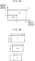
- Fig. 2A shows in a graph the relationship between the numbers of horizontal and vertical pixels for the pictures A, B and C. Numbers of pixels in a horizontal direction are shown in the horizontal axis and numbers of pixels in vertical direction are shown in the vertical axis. Numbers of horizontal and vertical pixels for each picture are expressed by a dark large dot. Both the pictures A and B have the same number of horizontal pixels H1 and the same number of vertical pixels V1 respectively, and the picture C has a number of horizontal pixels H2 (> H1) and a number of vertical pixels V2 (> V1). It is assumed that the picture D which is the output of the band limiting circuit 20 has the number H1 of horizontal pixels and the number V1 of vertical pixels, which are the same numbers of the picture B respectively. Fig.
- the picture A has the ratio of 4:3 and the pictures B, C and D have the ratio of 16:9.
- the picture A corresponds to a standard television signal
- the pictures B and D to wide versions of the standard television signal
- the picture C to the signal of a high-definition television (HDTV).
- HDTV high-definition television
- the band limiting circuit 20 can be structured by a vertical thinning circuit 21 for limiting the band in a vertical direction to reduce the number of vertical pixels and a horizontal thinning circuit 22 for limiting the band in a horizontal direction to reduce the number of horizontal pixels, as shown in Fig. 3.
- both the picture C and the picture D have the same horizontal to vertical screen frame ratio of 16:9. Therefore, the vertical thinning circuit 21 limits the band of the picture C in the vertical direction to V1/V2, and the horizontal thinning circuit 22 limits the band of the picture C in the horizontal direction to H1/H2.
- the differential circuit 30 may be structured by a vertical interpolating circuit 31 for interpolating the pixels in the vertical direction, a horizontal interpolating circuit 32 for interpolating the pixels in the horizontal direction and a subtracting circuit 33, as shown in Fig. 3.
- the vertical interpolating circuit 31 interpolates the number of pixels that have been eliminated by the vertical thinning circuit 21 to recover the number V2 of vertical pixels
- the horizontal interpolating circuit interpolates the number of pixels that have been eliminated by the horizontal thinning circuit 22 to recover the number H2 of horizontal pixels.
- the numbers of the horizontal and vertical pixels of a signal after the interpolation are the same as those of the picture C. However, the signal components of the picture after the interpolation are limited to the frequency components included in the picture D.
- an input picture A, B or D to the first encoding circuit 50 has the number of horizontal pixels H1 and the number of vertical pixels V1. Therefore, regardless of the mode of encoding, the first encoding circuit 50 produces the encoded signal X having the same data quantity by the same processing and at the same compression ratio.
- the first encoding circuit 50 itself can execute the encoding processing according to the orthogonal transformation as described previously with Fig. 14.
- the second encoding circuit 51 encodes the additional picture E which is structured by only the high frequency components in the picture C, and produces the encoded signal Y.
- the encoding processing of the second encoding circuit 51 may of course be the same as the first encoding circuit 50.
- the additional picture E does not have the frequency components included in the picture D and, therefore, has little influence to the visual sense of a human being.
- the additional picture E includes only high frequency components of which deterioration is not easily visually recognized comparing to low frequency components. Therefore, the compression rate in the second encoding circuit 51 may be higher than that in the first encoding circuit 50.
- the encoding processing may be done by a separate processing such as a predictive coding instead of the processing by orthogonal transformation.
- FIG. 7 shows an example of the configuration of the decoding apparatus.
- numeral 160 designates an input terminal of a decoded signal X
- 161 designates an input terminal of a decoded signal Y
- 150 designates a first decoding circuit which performs an inverse processing of the first encoding circuit 50 to decode the encoded signal X, for obtaining pictures A′, B′ and D′ which are decoded pictures of the pictures A, B and D respectively
- 151 designates a second decoding circuit which performs an inverse processing of the second encoding circuit 51 to decode an encoded signal Y, for obtaining an additional picture E′ which is a decoded picture of an additional picture E.
- 130 designates a decoding interpolating circuit for interpolating the output of the decoding circuit 150 into a picture having the same number of pixels as that of the picture C.
- 133 designates an adder circuit for adding an output of the decoding interpolating circuit 130 to the output of the second decoding circuit 151.
- 110 designates an output terminal for providing an output of the first decoding circuit 150 as the picture A′
- 111 designates an output terminal for providing an output of the first decoding circuit as the picture B′
- 112 designates an output terminal for providing an output of the adder circuit 133 as the picture C′ which is a decoded picture of the picture C.
- the decoding interpolating circuit 130 is structured by the vertical interpolating circuit 31 and the horizontal interpolating circuit 32 which also structure the differential circuit 30 in Fig. 3. Therefore, the decoding interpolating circuit 130 in the decoding apparatus may be commonly used to the differential circuit 30 in the encoding apparatus when the adder circuit 133 replaces the subtraction function of the subtracting circuit 33 of the differential circuit 30 with the addition function.
- the first encoding circuit 50 of the encoding apparatus and the first decoding circuit 150 of the decoding apparatus are common structure elements and are exactly the same circuits for all the modes of the pictures A, B and C.
- Other structure elements excluding the switches are the circuits which are necessary in only the mode of the picture C. Accordingly, a signal which has been encoded in the mode of the picture C can also be decoded by an exclusive decoding apparatus for picture A or B.
- the picture C is encoded by the encoding apparatus of the present embodiment, not only the picture C′ can be obtained by the decoding apparatus shown in Fig.
- the picture A′ or B′ can also be obtained from only the encoded signal X by the exclusive decoding apparatus exclusive for picture A or B having only the first decoding circuit 150.
- the encoding circuit can produce an output as the picture C′ assuming that the encoded signal Y in Fig. 7 has no information.
- the first encoding circuit 50 is a structure element common to all the modes of the pictures A, B and C, requiring no additional separate circuit in each mode, and the encoded data of any one of these input pictures can be decoded by any decoding apparatus.
- FIG. 4A and 4B show the relationship between the numbers of horizontal and vertical pixels of the pictures A, B and C respectively in the present embodiment
- Fig. 5 shows a structure block diagram of the band limiting circuit 20 and the differential circuit 30.
- the picture B has the horizontal to vertical screen frame ratio of 16:9 which gives a wider screen than that of the picture A, through the picture B has the same number of horizontal pixels as that of the picture A.
- the number of horizontal pixels becomes smaller, or the band is narrower, than that of the data which is a result of encoding the picture A
- the decoded picture is to be displayed by keeping the number of the vertical pixels to be the same as that of the picture A.
- the number of the vertical pixels needs to be reduced to display the vertical areas of the display screen only in the mode of letter box by no signal in upper and lower end portions in the screen.
- the number of the horizontal pixels of the picture B is H3 which is larger than the number H1 of the horizontal pixels of the picture A and the number of the horizontal pixels of the picture C is H3 which is the same as that of the picture B, although the horizontal to vertical screen frame ratio of the picture A is 4:3 and the horizontal to vertical screen frame ratio of the pictures B and C is 16:9, which remain the same as the case of the first embodiment.
- This H3 is resulted from increasing the number of pixels corresponding to a wider screen having the horizontal to vertical screen frame ratio of 16:9 for the picture B changed from the ratio of 4:3 for the picture A.
- H1:H3 becomes the ratio of 3:4 and H3 is 4/3 of the size of H1.
- a partial picture which is the portion of H1 extracted from the horizontal pixels numbered H3 of the picture B has the horizontal to vertical screen frame ratio of 4:3, having exactly the same numbers of the horizontal and vertical pixels as the picture A. Therefore, the encoded data X which is a result of encoding a picture in the mode of the picture B can be decoded by the decoding apparatus exclusive for the mode of the picture A and can be displayed without narrowing the horizontal band if only the number of H1 of the horizontal pixels are used.
- a detailed configuration of the first encoding circuit which can be compatibly used for the picture A and the picture B has been applied for a patent by the present applicant under the Japanese Patent Application No. H3-15191.
- the picture C has the number V2 of vertical pixels which is larger than the number V1 of vertical pixels of the picture B and has the number H3 of horizontal pixels which is the same as that of the picture B.
- a bit rate reducing circuit 20 shown in Fig. 5 needs to have a structure of only the vertical thinning circuit 21, and similarly, the differential circuit 30 needs to have a structure of only the vertical interpolating circuit 31 and the subtracting circuit 33.
- the decoding interpolating circuit 130 in Fig. 7 can be structured by only the vertical interpolating circuit 31.
- a block diagram of the configuration of the third embodiment is the same as the configuration of the first and second embodiments, and is therefore emitted.
- the third embodiment is different from the first and second embodiments in the relationship between the numbers of horizontal and vertical pixels of the pictures A, B and C.
- Figs. 6A and 6B show the relationship between the numbers of horizontal and vertical pixels for the pictures A, B and C.
- the picture C for a high-definition television signal requires about two times of the number of the vertical pixels of the picture A used for a standard television signal, or the picture B for a wide television signal. From the above relationship of the transmission band and the number of scanning lines, the picture C requires about two times of the number of vertical pixels of the picture B and about two times of the number of horizontal pixels of the picture B if the picture C is transmitted in the transmission band of the high-definition television signal for broadcasting.
- the picture C requires about two times of the number of vertical pixels of the picture B and about 1.25 time of the number of horizontal pixels of the picture B if the picture C is transmitted in the transmission band for home use. Accordingly, when the high-definition television signal of the frequency 30 MHz or 20 MHz is used for the picture C, the above-described relationship of the numbers of horizontal and vertical pixels exists and this relationship can be obtained by the present embodiment.
- the additional picture E can be encoded at the compressing rate with additional 2/3 time of the compressing rate of the picture D to make the quantity of the encoded data X exactly the same as the quantity of the data Y.
- the picture C can be recorded by a double channel recording of the picture A or picture B because the data quantity of the mode of the picture C is just two times of the data quantity of the mode of the picture A or picture B. The compatibility of the recording pattern is also good in this case.
- a high-definition television signal recorded on a tape can be completely reproduced as a standard television signal by a video tape recorder exclusive for a standard television signal, so that the tape can be compatibly used with high efficiency.
- the number of vertical pixels may be V2 - V1 and the pixels may be thinned by limiting the band such that the high frequency components in the vertical direction are extracted.
- the similar processing is further carried out in the horizontal direction.
- the frequency of the picture C has been explained above as 30 MHz or 20 MHz for a high-definition television signal in the explanation of the encoding apparatus of the present invention.
- the frequency may change, as a matter of fact, depending on the sampling frequency for sampling the high-definition television signal.
- the numbers of the horizontal and vertical pixels of the picture C respectively are determined by the number of sampling frequencies, and therefore, the thinning and interpolating rate to the picture D may be determined according to the numbers of the horizontal and vertical pixels respectively.
- the encoded data X and Y are produced.
- the encoded data Y is the data necessary in only the mode for encoding the picture C. Accordingly, only the first encoding apparatus 50 can structure the encoding apparatus exclusive for the mode of the picture A or picture B and only the first decoding apparatus 150 can structure the decoding apparatus exclusive for the mode of the picture A or picture B.
- Fig. 8 is a block diagram for showing a configuration of the encoding apparatus according to a fourth embodiment of the present invention.
- 10 designates an input terminal for inputting a picture A of which horizontal to vertical screen frame ratio is 4:3 or 16:9
- 12 designates an input terminal for inputting a picture C of which horizontal to vertical screen frame ratio is 16:9.
- 200 designates a thinning filter for limiting the band of the picture C to obtain a picture D having the same numbers of horizontal and vertical pixels as those of the picture A respectively
- 400 designates a switch for outputting the picture A in the mode for encoding the picture A and for outputting the picture D in the mode for encoding the picture C.
- the picture C is a high-definition television signal having the horizontal to vertical screen frame ratio of 16:9.
- the picture A is a standard television signal with the horizontal to vertical screen frame ratio of 4:3 or a wide version of a standard television signal with the horizontal to vertical screen frame ratio of the picture A is 16:9.
- the thinning filter 200 limits the band of the picture C in the horizontal direction to H1/H2 and limits the band in the vertical direction to V1/V2. After limiting the band as described above, the thinning filter 200 thins the pixels to produce the picture D which has the same numbers of the horizontal and vertical pixels respectively of the picture A. Accordingly, regardless of the mode of the switch 400, the first encoder 500 outputs the encoded signal X of the same quantity of data by exactly the same processing at the same compressing ratio.
- the processing of the first encoder 500 may be the encoding processing according to the orthogonal transformation explained in Fig. 14.
- the interpolating filter 210 receives the reproduced signal A′ of the picture D to interpolate the number of the thinned pixels of the picture A′ and produces an output of the picture D′ which has the same numbers of the horizontal and vertical pixels H2 and V2 respectively as those of the picture C. Since the picture D′ is obtained as a result of the thinning and interpolating processings, the picture D′ has a narrower band than the picture C. Further, since the picture D′ is obtained after the encoding and decoding processings, errors due to these processings are also included in the picture D′.
- the additional picture E which is the output of the subtractor 300 is a signal which consists of the high frequency components obtained after subtracting the frequency components of the picture D′ from the frequency components of the picture C and the error components generated as a result of the encoding and decoding processings.
- the second encoder 510 encodes the additional picture E and produces an output of the encoded signal Y.
- the encoding processing by the second encoder 510 may of course be the same as that of the first encoder 500.
- the additional picture E does not include the low frequency components which influence greatly to the visual sensation of the human being
- the compressing ratio in the second encoder 510 may be higher than the compressing ratio of the first encoder 500.
- the encoding processing of the second encoder 510 may be any adequate encoding processing such as predictive encoding as well as the processing by the orthogonal transformation.
- the first encoder 500 and the first decoder 600 are the common structure elements for both modes of the pictures A and C, and they are exactly the same circuits in both of these modes.
- the rest of structure elements are the circuits which are necessary only in the mode of the picture C. Accordingly, a signal encoded in the mode of the picture C can also be decoded by the decoding apparatus exclusive for the mode of the picture A.
- the picture C′ can be obtained by the decoding apparatus shown in Fig.
- the first encoder 500 and the first decoder 600 are common structure elements commonly used for the pictures A and C, and it is not necessary to structure different circuits for both modes. An encoded signal of any one of these input signals can be decoded by any decoder.
- a block diagram of the configuration of the present invention is the same as that of the fourth embodiment, and is therefore emitted.
- the present embodiment is different from the fourth embodiment in the method of thinning the picture C.
- An example configuration of the second encoder 510 for the present embodiment will be explained.
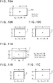
- Figs. 11A, 11B and 11C show the relationship between the numbers of horizontal and vertical pixels for the pictures A and C respectively in the present embodiment.
- Fig. 12 shows a block diagram of a configuration of one embodiment of the second encoder 510, and Fig. 13 shows a conceptional diagram of the signal used for explaining the operation of the second encoder 510.
- the pictures A and C have the relationship of H2 > H1 and V2 > V1 similar to the pictures in the fourth embodiment.
- the picture C is a high-definition television signal, and the picture A is either a standard version or a wide version of the standard television signal.
- the thinning filter 200 inputs the area of the picture C with the number of horizontal pixels H3 and the number of vertical pixels V3 shown in Figs. 11A, 11B and 11C.
- the relationship between the numbers of the pixels is H2 ⁇ H3 ⁇ H1 and V2 ⁇ V3 > V1.
- the picture D which is the output of the thinning filter 200 is obtained from the picture C by limiting the band of the area shown by a broken line to H1/H3 in the horizontal direction and V1/V3 in the vertical direction and then thinning the pixels from the picture C.
- the broken line portion in the picture C is displayed when the encoded signal X of the picture C is decoded by the decoding apparatus exclusive for the mode of the picture A.
- the ratio of H3 to V3 is set to H3:V3 ⁇ 4:3, and when the horizontal to vertical screen frame ratio of the picture A is 16:9, the ratio of H3 to V3 is set to H3:V3 ⁇ 16:9, so that a picture free from vertical expanding or horizontal expanding can be obtained on the screen of the decoding apparatus exclusive for the picture A.
- the picture D which is the output of the thinning filter 200 is obtained from the picture C by thinning the dotted line area with the number of horizontal pixels H3 and the number of vertical pixels V3 shown in Figs. 11a, 11B and 11C, so that the picture D′ which is the output of the interpolating filter 210 has the size having the number of horizontal pixels H3 and the number of vertical pixels V3.
- the subtracter 300 subtracts the picture D′ from the picture C, and therefore the additional picture E is different from the one obtained in the fourth embodiment.
- the additional picture E has the area inside the dotted line of the picture C, shown in Figs.
- a control signal is inputted to the quantizer 516 to define whether the blocks are for the picture C itself or the difference between the picture C and the picture C′.
- the output blocks of the quantizer 516 have the size of 4 x 4, for example.
- the orthogonal transformer 513 which receives the block signal produces an output signal S1 expanding in two dimension from the low frequency to the high frequency, with s0 as a DC component, as shown in Fig. 13A.
- the DC component s0 shows an average level of the blocks, and when the blocks are for the picture C itself a variety of cases exist. When the blocks are for the differential components, the DC component s0 becomes a small value in many cases.
- 13C shows an output signal s2 of the quantizer 516 after processing the blocks of the differential components between the picture C and the picture D′, where all the components including the DC component s0 have been quantized by the quantizing coefficient k. It is needless to mention that there are two ways of decoding when the second decoder 610 is used.
- the first encoder 500 and the first decoder 600 are common structure elements for the picture A and the picture C, and an encoded signal of any one of these input pictures can be decoded by any decoding apparatus.
- the picture D obtained by the thinning filter 200 can be matched to the horizontal to vertical screen frame ratio of the picture A, so that it is possible to avoid an unnatural ratio of the horizontal to vertical screen frame appearing on the screen when the encoded signal of the picture C is decoded in the mode of the picture A.
- first decoder 600 and the second interpolating filter 211 which are the structure elements of the decoding apparatus in each of the above embodiments can be shared with the decoder 520 and the first interpolating filter 210 of the encoding apparatus.
- the second encoder 500 in the fifth embodiment can also be used in the fourth embodiment, and the second encoder 500 can also be used in the structure for obtaining the picture D′ by directly interpolating the picture D instead of encoding and decoding the picture D.
Landscapes
- Engineering & Computer Science (AREA)
- Multimedia (AREA)
- Signal Processing (AREA)
- Computer Graphics (AREA)
- Compression Or Coding Systems Of Tv Signals (AREA)
Applications Claiming Priority (4)
| Application Number | Priority Date | Filing Date | Title |
|---|---|---|---|
| JP114326/91 | 1991-05-20 | ||
| JP3114326A JPH04342388A (ja) | 1991-05-20 | 1991-05-20 | 符号化装置 |
| JP24309791A JP3275328B2 (ja) | 1991-09-24 | 1991-09-24 | 符号化および復号化装置 |
| JP243097/91 | 1991-09-24 |
Publications (3)
| Publication Number | Publication Date |
|---|---|
| EP0515143A2 true EP0515143A2 (de) | 1992-11-25 |
| EP0515143A3 EP0515143A3 (en) | 1994-06-08 |
| EP0515143B1 EP0515143B1 (de) | 1997-10-15 |
Family
ID=26453100
Family Applications (1)
| Application Number | Title | Priority Date | Filing Date |
|---|---|---|---|
| EP92304529A Expired - Lifetime EP0515143B1 (de) | 1991-05-20 | 1992-05-19 | Videosignal-Kodierungs- und Dekodierungsgerät |
Country Status (4)
| Country | Link |
|---|---|
| US (1) | US5367334A (de) |
| EP (1) | EP0515143B1 (de) |
| KR (1) | KR950004125B1 (de) |
| DE (1) | DE69222683D1 (de) |
Cited By (7)
| Publication number | Priority date | Publication date | Assignee | Title |
|---|---|---|---|---|
| EP0541313A3 (en) * | 1991-11-05 | 1993-06-09 | Matsushita Electric Industrial Co., Ltd. | Video signal encoding apparatus |
| EP0643535A4 (de) * | 1993-03-26 | 1995-12-06 | Sony Corp | Verfahren und vorrichtung zur kodierung/dekodierung eines videosignals. |
| WO1997001934A1 (en) * | 1995-06-29 | 1997-01-16 | Thomson Multimedia S.A. | System for encoding and decoding layered compressed video data |
| WO1998041011A1 (en) * | 1997-03-12 | 1998-09-17 | Matsushita Electric Industrial Co., Ltd. | Hdtv downconversion system |
| US6487249B2 (en) | 1998-10-09 | 2002-11-26 | Matsushita Electric Industrial Co., Ltd. | Efficient down conversion system for 2:1 decimation |
| US6618443B1 (en) | 1997-03-12 | 2003-09-09 | Matsushita Electric Industrial Co., Ltd. | Upsampling filter for a down conversion system |
| US6788347B1 (en) | 1997-03-12 | 2004-09-07 | Matsushita Electric Industrial Co., Ltd. | HDTV downconversion system |
Families Citing this family (16)
| Publication number | Priority date | Publication date | Assignee | Title |
|---|---|---|---|---|
| KR930011288B1 (ko) * | 1991-01-17 | 1993-11-29 | 삼성전자 주식회사 | 영상신호 대역 압축 전송을 위한 dc 성분 추출장치 |
| JP3132184B2 (ja) * | 1992-09-04 | 2001-02-05 | 株式会社日立製作所 | 画像データ記録再生装置 |
| US5459585A (en) * | 1992-09-09 | 1995-10-17 | Hitachi, Ltd. | Apparatus and method of storing image signals |
| JPH07143487A (ja) * | 1993-11-17 | 1995-06-02 | Canon Inc | 画像符号化装置 |
| US5586200A (en) * | 1994-01-07 | 1996-12-17 | Panasonic Technologies, Inc. | Segmentation based image compression system |
| KR960020415A (ko) * | 1994-11-23 | 1996-06-17 | 윌리엄 이. 힐러 | 디지탈 텔레비젼을 위한 특수 기능 |
| US6091455A (en) * | 1997-01-31 | 2000-07-18 | Hughes Electronics Corporation | Statistical multiplexer for recording video |
| US6084910A (en) * | 1997-01-31 | 2000-07-04 | Hughes Electronics Corporation | Statistical multiplexer for video signals |
| US6097435A (en) * | 1997-01-31 | 2000-08-01 | Hughes Electronics Corporation | Video system with selectable bit rate reduction |
| US6078958A (en) * | 1997-01-31 | 2000-06-20 | Hughes Electronics Corporation | System for allocating available bandwidth of a concentrated media output |
| US6188436B1 (en) | 1997-01-31 | 2001-02-13 | Hughes Electronics Corporation | Video broadcast system with video data shifting |
| US6005620A (en) * | 1997-01-31 | 1999-12-21 | Hughes Electronics Corporation | Statistical multiplexer for live and pre-compressed video |
| US5847760A (en) * | 1997-05-22 | 1998-12-08 | Optibase Ltd. | Method for managing video broadcast |
| JP4152280B2 (ja) * | 2003-08-27 | 2008-09-17 | 富士フイルム株式会社 | 映像信号出力方法、映像信号出力装置及びデジタルカメラ |
| US20060245737A1 (en) * | 2005-04-29 | 2006-11-02 | Walker Philip M | Combining different content discs for playback of supplemental content |
| CN106791842A (zh) * | 2011-09-06 | 2017-05-31 | 英特尔公司 | 分析辅助编码 |
Family Cites Families (10)
| Publication number | Priority date | Publication date | Assignee | Title |
|---|---|---|---|---|
| US4651208A (en) * | 1985-03-18 | 1987-03-17 | Scientific Atlanta, Inc. | Compatibility of widescreen and non-widescreen television transmissions |
| FR2625060B1 (fr) * | 1987-12-16 | 1990-10-05 | Guichard Jacques | Procede et dispositifs de codage et de decodage pour la transmission d'images a travers un reseau a debit variable |
| GB8804720D0 (en) * | 1988-02-29 | 1988-03-30 | Rca Licensing Corp | Compatible widescreen tv |
| US5191417A (en) * | 1988-09-02 | 1993-03-02 | North American Philips Corporation | Compatible EDTV system providing multi-aspect ratio display on EDTV and conventional television receivers |
| DE58903019D1 (de) * | 1988-09-13 | 1993-01-28 | Thomson Brandt Gmbh | Uebertragungssystem fuer ein zeitlich und oertlich hochaufgeloestes bildsignal. |
| CA2012922A1 (en) * | 1989-03-28 | 1990-09-28 | Marcel Fuhren | Extended composite television system |
| JPH03198593A (ja) * | 1989-12-27 | 1991-08-29 | Nippon Television Network Corp | テレビジョン方式 |
| US5010402A (en) * | 1990-05-17 | 1991-04-23 | Matsushita Electric Industrial Co., Ltd. | Video signal compression apparatus |
| GB9013217D0 (en) * | 1990-06-13 | 1990-08-01 | Indep Broadcasting Authority | Evaluation of detail in video images,and applications thereof |
| JPH04249490A (ja) * | 1991-02-06 | 1992-09-04 | Matsushita Electric Ind Co Ltd | 符号化装置 |
-
1992
- 1992-05-14 US US07/882,927 patent/US5367334A/en not_active Expired - Lifetime
- 1992-05-19 EP EP92304529A patent/EP0515143B1/de not_active Expired - Lifetime
- 1992-05-19 DE DE69222683T patent/DE69222683D1/de not_active Expired - Fee Related
- 1992-05-20 KR KR1019920008533A patent/KR950004125B1/ko not_active Expired - Fee Related
Cited By (11)
| Publication number | Priority date | Publication date | Assignee | Title |
|---|---|---|---|---|
| EP0541313A3 (en) * | 1991-11-05 | 1993-06-09 | Matsushita Electric Industrial Co., Ltd. | Video signal encoding apparatus |
| US5345268A (en) * | 1991-11-05 | 1994-09-06 | Matsushita Electric Industrial Co., Ltd. | Standard screen image and wide screen image selective receiving and encoding apparatus |
| EP0643535A4 (de) * | 1993-03-26 | 1995-12-06 | Sony Corp | Verfahren und vorrichtung zur kodierung/dekodierung eines videosignals. |
| US5832124A (en) * | 1993-03-26 | 1998-11-03 | Sony Corporation | Picture signal coding method and picture signal coding apparatus, and picture signal decoding method and picture signal decoding apparatus |
| WO1997001934A1 (en) * | 1995-06-29 | 1997-01-16 | Thomson Multimedia S.A. | System for encoding and decoding layered compressed video data |
| US6553072B1 (en) | 1995-06-29 | 2003-04-22 | Thomson Licensing S.A. | System for encoding and decoding layered compressed video data |
| WO1998041011A1 (en) * | 1997-03-12 | 1998-09-17 | Matsushita Electric Industrial Co., Ltd. | Hdtv downconversion system |
| US6618443B1 (en) | 1997-03-12 | 2003-09-09 | Matsushita Electric Industrial Co., Ltd. | Upsampling filter for a down conversion system |
| US6788347B1 (en) | 1997-03-12 | 2004-09-07 | Matsushita Electric Industrial Co., Ltd. | HDTV downconversion system |
| EP1628479A3 (de) * | 1997-03-12 | 2007-09-05 | Matsushita Electric Industrial Co., Ltd. | Abwärtsumwandlungssystem für HDTV-signale |
| US6487249B2 (en) | 1998-10-09 | 2002-11-26 | Matsushita Electric Industrial Co., Ltd. | Efficient down conversion system for 2:1 decimation |
Also Published As
| Publication number | Publication date |
|---|---|
| EP0515143A3 (en) | 1994-06-08 |
| KR920022902A (ko) | 1992-12-19 |
| KR950004125B1 (ko) | 1995-04-25 |
| EP0515143B1 (de) | 1997-10-15 |
| US5367334A (en) | 1994-11-22 |
| DE69222683D1 (de) | 1997-11-20 |
Similar Documents
| Publication | Publication Date | Title |
|---|---|---|
| EP0515143B1 (de) | Videosignal-Kodierungs- und Dekodierungsgerät | |
| JP2795420B2 (ja) | デジタル化映像信号の圧縮方法とその装置及びシステム | |
| US5371549A (en) | Decoding method and system for providing digital television receivers with multipicture display by way of zero masking transform coefficients | |
| US5434622A (en) | Image signal encoding apparatus using adaptive frame/field format compression | |
| US7092445B2 (en) | Video coder providing implicit coefficient prediction and scan adaptation for image coding and intra coding of video | |
| KR100370076B1 (ko) | 다운 컨버젼 기능을 갖는 비디오 디코더 및 비디오 신호를디코딩 하는 방법 | |
| HU224291B1 (hu) | Csökkentett képfelbontású vevőkészülék nagy képfelbontású televíziós rendszerhez | |
| EP0993198A2 (de) | Effizientes Abwärtsumwandlungsystem zur 2:1-dezimierung eines Videosignales | |
| US6665343B1 (en) | Methods and arrangements for a converting a high definition image to a lower definition image using wavelet transforms | |
| EP0644697A2 (de) | Verfahren zur halbpixel Bewegungskompensation in Bilddekodierung | |
| US6993076B1 (en) | Apparatus and method for deriving an enhanced decoded reduced-resolution video signal from a coded high-definition video signal | |
| US9693051B2 (en) | Video coder providing implicit coefficient prediction and scan adaptation for image coding and intra coding of video | |
| JPH1175180A (ja) | 画像処理装置および画像処理方法、並びに伝送媒体および伝送方法 | |
| JPH08154251A (ja) | 画像信号補間装置 | |
| US5432555A (en) | Image signal encoding apparatus using adaptive 1D/2D DCT compression technique | |
| US5889562A (en) | Memory requirement reduction in a SQTV processor by ADPCM compression | |
| US5136379A (en) | Video signal processing device capable of vertical blocking | |
| JPH0937243A (ja) | 動画像符号化装置及び復号装置 | |
| US5734757A (en) | Post-processing method and apparatus for use in an image signal decoding system | |
| EP0920212B1 (de) | Vorrichtung zur Videokodierung | |
| KR20000011665A (ko) | 디코딩되어감소된해상도의비디오신호를코드화된고해상도의비디오신호로부터유도하는시스템 | |
| EP0720372A1 (de) | Vorrichtung zur parallelen Kodierung/Dekodierung von digitalen Bildsignalen | |
| JPH0678297A (ja) | ディジタルビデオ信号の符号化方法 | |
| JP3275328B2 (ja) | 符号化および復号化装置 | |
| JPH07160865A (ja) | 静止画再生装置 |
Legal Events
| Date | Code | Title | Description |
|---|---|---|---|
| PUAI | Public reference made under article 153(3) epc to a published international application that has entered the european phase |
Free format text: ORIGINAL CODE: 0009012 |
|
| AK | Designated contracting states |
Kind code of ref document: A2 Designated state(s): DE FR GB NL |
|
| PUAL | Search report despatched |
Free format text: ORIGINAL CODE: 0009013 |
|
| AK | Designated contracting states |
Kind code of ref document: A3 Designated state(s): DE FR GB NL |
|
| 17P | Request for examination filed |
Effective date: 19941024 |
|
| GRAG | Despatch of communication of intention to grant |
Free format text: ORIGINAL CODE: EPIDOS AGRA |
|
| 17Q | First examination report despatched |
Effective date: 19961206 |
|
| GRAH | Despatch of communication of intention to grant a patent |
Free format text: ORIGINAL CODE: EPIDOS IGRA |
|
| GRAH | Despatch of communication of intention to grant a patent |
Free format text: ORIGINAL CODE: EPIDOS IGRA |
|
| GRAA | (expected) grant |
Free format text: ORIGINAL CODE: 0009210 |
|
| AK | Designated contracting states |
Kind code of ref document: B1 Designated state(s): DE FR GB NL |
|
| REF | Corresponds to: |
Ref document number: 69222683 Country of ref document: DE Date of ref document: 19971120 |
|
| ET | Fr: translation filed | ||
| PLBE | No opposition filed within time limit |
Free format text: ORIGINAL CODE: 0009261 |
|
| STAA | Information on the status of an ep patent application or granted ep patent |
Free format text: STATUS: NO OPPOSITION FILED WITHIN TIME LIMIT |
|
| 26N | No opposition filed | ||
| REG | Reference to a national code |
Ref country code: GB Ref legal event code: IF02 |
|
| PGFP | Annual fee paid to national office [announced via postgrant information from national office to epo] |
Ref country code: FR Payment date: 20040510 Year of fee payment: 13 |
|
| PGFP | Annual fee paid to national office [announced via postgrant information from national office to epo] |
Ref country code: GB Payment date: 20040519 Year of fee payment: 13 |
|
| PGFP | Annual fee paid to national office [announced via postgrant information from national office to epo] |
Ref country code: DE Payment date: 20040527 Year of fee payment: 13 |
|
| PG25 | Lapsed in a contracting state [announced via postgrant information from national office to epo] |
Ref country code: GB Free format text: LAPSE BECAUSE OF NON-PAYMENT OF DUE FEES Effective date: 20050519 |
|
| PG25 | Lapsed in a contracting state [announced via postgrant information from national office to epo] |
Ref country code: DE Free format text: LAPSE BECAUSE OF NON-PAYMENT OF DUE FEES Effective date: 20051201 |
|
| GBPC | Gb: european patent ceased through non-payment of renewal fee |
Effective date: 20050519 |
|
| PG25 | Lapsed in a contracting state [announced via postgrant information from national office to epo] |
Ref country code: FR Free format text: LAPSE BECAUSE OF NON-PAYMENT OF DUE FEES Effective date: 20060131 |
|
| REG | Reference to a national code |
Ref country code: FR Ref legal event code: ST Effective date: 20060131 |
|
| PGFP | Annual fee paid to national office [announced via postgrant information from national office to epo] |
Ref country code: NL Payment date: 20060517 Year of fee payment: 15 |
|
| PG25 | Lapsed in a contracting state [announced via postgrant information from national office to epo] |
Ref country code: NL Free format text: LAPSE BECAUSE OF NON-PAYMENT OF DUE FEES Effective date: 20071201 |
|
| NLV4 | Nl: lapsed or anulled due to non-payment of the annual fee |
Effective date: 20071201 |