EP0516337B1 - Connecteur à fibre optique à haute précision - Google Patents
Connecteur à fibre optique à haute précision Download PDFInfo
- Publication number
- EP0516337B1 EP0516337B1 EP92304595A EP92304595A EP0516337B1 EP 0516337 B1 EP0516337 B1 EP 0516337B1 EP 92304595 A EP92304595 A EP 92304595A EP 92304595 A EP92304595 A EP 92304595A EP 0516337 B1 EP0516337 B1 EP 0516337B1
- Authority
- EP
- European Patent Office
- Prior art keywords
- holder
- fiber
- groove
- holders
- receiving
- Prior art date
- Legal status (The legal status is an assumption and is not a legal conclusion. Google has not performed a legal analysis and makes no representation as to the accuracy of the status listed.)
- Expired - Lifetime
Links
- 239000013307 optical fiber Substances 0.000 title claims description 20
- 239000000835 fiber Substances 0.000 claims description 88
- 230000013011 mating Effects 0.000 claims description 9
- XUIMIQQOPSSXEZ-UHFFFAOYSA-N Silicon Chemical compound [Si] XUIMIQQOPSSXEZ-UHFFFAOYSA-N 0.000 claims description 4
- 230000000284 resting effect Effects 0.000 claims description 4
- 229910052710 silicon Inorganic materials 0.000 claims description 4
- 239000010703 silicon Substances 0.000 claims description 4
- 239000000758 substrate Substances 0.000 claims description 4
- 239000011521 glass Substances 0.000 claims description 3
- 238000005530 etching Methods 0.000 claims description 2
- 230000000452 restraining effect Effects 0.000 claims 2
- 230000007246 mechanism Effects 0.000 description 5
- 238000013459 approach Methods 0.000 description 2
- 239000002184 metal Substances 0.000 description 2
- 230000000087 stabilizing effect Effects 0.000 description 2
- 230000008878 coupling Effects 0.000 description 1
- 238000010168 coupling process Methods 0.000 description 1
- 238000005859 coupling reaction Methods 0.000 description 1
- 238000010586 diagram Methods 0.000 description 1
- 239000000428 dust Substances 0.000 description 1
- 238000005516 engineering process Methods 0.000 description 1
- 239000000463 material Substances 0.000 description 1
- 238000000034 method Methods 0.000 description 1
- 230000007935 neutral effect Effects 0.000 description 1
- 239000005304 optical glass Substances 0.000 description 1
- 239000013618 particulate matter Substances 0.000 description 1
- 229910052594 sapphire Inorganic materials 0.000 description 1
- 239000010980 sapphire Substances 0.000 description 1
- 238000000926 separation method Methods 0.000 description 1
- 235000012431 wafers Nutrition 0.000 description 1
- 229910052845 zircon Inorganic materials 0.000 description 1
- GFQYVLUOOAAOGM-UHFFFAOYSA-N zirconium(iv) silicate Chemical compound [Zr+4].[O-][Si]([O-])([O-])[O-] GFQYVLUOOAAOGM-UHFFFAOYSA-N 0.000 description 1
Images


Classifications
-
- G—PHYSICS
- G02—OPTICS
- G02B—OPTICAL ELEMENTS, SYSTEMS OR APPARATUS
- G02B6/00—Light guides; Structural details of arrangements comprising light guides and other optical elements, e.g. couplings
- G02B6/24—Coupling light guides
- G02B6/36—Mechanical coupling means
- G02B6/38—Mechanical coupling means having fibre to fibre mating means
- G02B6/3807—Dismountable connectors, i.e. comprising plugs
- G02B6/3833—Details of mounting fibres in ferrules; Assembly methods; Manufacture
- G02B6/3855—Details of mounting fibres in ferrules; Assembly methods; Manufacture characterised by the method of anchoring or fixing the fibre within the ferrule
- G02B6/3858—Clamping, i.e. with only elastic deformation
-
- G—PHYSICS
- G02—OPTICS
- G02B—OPTICAL ELEMENTS, SYSTEMS OR APPARATUS
- G02B6/00—Light guides; Structural details of arrangements comprising light guides and other optical elements, e.g. couplings
- G02B6/24—Coupling light guides
- G02B6/26—Optical coupling means
- G02B6/32—Optical coupling means having lens focusing means positioned between opposed fibre ends
-
- G—PHYSICS
- G02—OPTICS
- G02B—OPTICAL ELEMENTS, SYSTEMS OR APPARATUS
- G02B6/00—Light guides; Structural details of arrangements comprising light guides and other optical elements, e.g. couplings
- G02B6/24—Coupling light guides
- G02B6/36—Mechanical coupling means
- G02B6/38—Mechanical coupling means having fibre to fibre mating means
- G02B6/3807—Dismountable connectors, i.e. comprising plugs
- G02B6/3833—Details of mounting fibres in ferrules; Assembly methods; Manufacture
- G02B6/3855—Details of mounting fibres in ferrules; Assembly methods; Manufacture characterised by the method of anchoring or fixing the fibre within the ferrule
-
- G—PHYSICS
- G02—OPTICS
- G02B—OPTICAL ELEMENTS, SYSTEMS OR APPARATUS
- G02B6/00—Light guides; Structural details of arrangements comprising light guides and other optical elements, e.g. couplings
- G02B6/24—Coupling light guides
- G02B6/36—Mechanical coupling means
- G02B6/38—Mechanical coupling means having fibre to fibre mating means
- G02B6/3807—Dismountable connectors, i.e. comprising plugs
- G02B6/3873—Connectors using guide surfaces for aligning ferrule ends, e.g. tubes, sleeves, V-grooves, rods, pins, balls
- G02B6/3885—Multicore or multichannel optical connectors, i.e. one single ferrule containing more than one fibre, e.g. ribbon type
-
- G—PHYSICS
- G02—OPTICS
- G02B—OPTICAL ELEMENTS, SYSTEMS OR APPARATUS
- G02B6/00—Light guides; Structural details of arrangements comprising light guides and other optical elements, e.g. couplings
- G02B6/24—Coupling light guides
- G02B6/36—Mechanical coupling means
- G02B6/38—Mechanical coupling means having fibre to fibre mating means
- G02B6/3807—Dismountable connectors, i.e. comprising plugs
- G02B6/389—Dismountable connectors, i.e. comprising plugs characterised by the method of fastening connecting plugs and sockets, e.g. screw- or nut-lock, snap-in, bayonet type
Definitions
- This invention relates to optical fiber connectors and, more particularly, to a multi-purpose optical fiber connector that provides precise fiber-end alignment in 3-dimensional space using few and inexpensive precision components.
- the mechanisms for aligning the fibers include upper and lower fiber-holding plates or substrates integrally fixed in the respective housings.
- the plates have fiber-receiving grooves.
- Each groove also contains an alignment sphere, fixed in location with respect to the fiber end, with the end and sphere spaced apart.
- the sphere center locates in the groove in line with the fiber core axis.
- the opposing V-grooves of the plates are congruent in the sense that the corresponding grooves of the two plates are located within the same inter-groove spacing.
- an actuator slidably mounted in the left housing is moved inwardly by contact with the right housing. This allows the fiber substrate in the left housing to pivot downward, with its associated sphere and fiber assembly coming to rest in the corresponding alignment groove formed in the floor of the right housing. With the ball and fiber of the right housing positioned in their respective alignment grooves, the fiber ends come to rest in the desired axial alignment.
- the alignment spheres besides providing precision axial alignment of the two fibers, also provide efficient focusing of the light emitted from the fiber ends through the spheres.
- a broad object of the invention is to connect one or more pairs of optical fibers quickly and reliably and in precise and stable coaxial alignment.
- Another object of the invention is to decrease the cost of gang-type optical fiber connectors and at the same time assure the needed precise and stable coaxial alignment.
- a general object of the invention is to provide a system for the connection of optical fiber which assures uniform and precise fiber end alignment regardless of how many fibers are accommodated into the connector.
- an initial gross positioning of the ball lenses is achieved by using a positioning element, such as a glass or metal cylinder, laterally offset from but precisely located with respect to the fiber-containing grooves of the lower fiber holder.
- a positioning element such as a glass or metal cylinder
- Two cylinders are employed on either side of the fiber-containing V-groove.
- lateral tapered sides are formed in the upper holders, which during movement of the connector halves, engage the cylinder or similar element.
- the tapered sides of the upper holder contact the positioning element.
- the resulting force "funnels” or urges the lense-sphere of the upper holder and the holder itself back toward the center of the receiving grooves of the lower holder. When the lense-sphere finds its groove, it slides down into it, coming to rest in the groove.
- the upper housing In its final position, the upper housing is free of contact with the positioning element, thereby avoiding possible interference by the element with the precision alignment of the fibers.
- a tripod system of spherical supports one leg of which is the lense-sphere of the upper fiber holder, retains the opposing groove surfaces of the lower and upper fiber holders in predetermined parallel planes, while at the same time preventing the lower and upper fiber holders from undergoing during usage any rotation within their respective plane, relative to one another. This result is critically important to maintaining true co-axial alignment of the mating fibers.
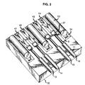
- lower fiber holder 10 has four fiber-receiving grooves 18-21.
- the sides of the grooves 18-21 are V-shaped.
- Each such groove is formed as an exterior segment 22 which begins at the edge 23 of the holder 10 and receives the jacketed part of the fiber end.
- a communicating interior segment 24 of the grooves 18-21 receives the stripped, unjacketed fiber end 27.
- FIG. 3 shows lower holder 10 with four optical fibers 13-16 disposed in the grooves 18-21.
- Each fiber has jacketing 17.
- the jacketing is removed from the end portion 9 of each fiber.
- the jacketed part resides in the exterior segments, and the stripped fiber end resides in the interior segment 24 of the grooves 18-21.
- each well 25 is configured as an inverse pyramid with a square base and four tapered sides denoted 26.
- Each well 25 receives a ball lens, such as the four spheres shown in FIG. 1.
- Each sphere 27 is precisely controlled in diameter and is sized to lodge in its well 25 so that, with the unjacketed fiber end portion 9 resting in its interior segment 24, the fiber's center axis 28 extends substantially through the geometric center of the sphere 26.
- each groove 33 is shaped similarly to the grooves 18-21 in lower housing 10, in that each groove 33 has an exterior segment 22 which receives the jacketed part 34 of a fiber end and a communicating interior segment 24 which receives the stripped, unjacketed fiber end 35.
- each well 36 Adjacent to the interior end 24 of each respective fiber groove 33 in upper housings 11, 12 there is formed a well 36.
- Each well 36 has the described inverse pyramid, square based shape with four tapered sides, similar to the well 25 of lower housing 10.
- Each well 36 is located just inboard of the end 39 of holder 11, 12.
- Each well 36 receives a lense-sphere such as sphere 37, which is sized to lodge in its well 25 so that, with the unjacketed fiber end 35 resting in its interior groove segment 24, the fiber's center axis 38 extends substantially through the geometric center of the sphere 37.
- V-shaped alignment grooves 41-44 there are formed four V-shaped alignment grooves 41-44.
- the bottom of the "V” of the grooves 41-44 are in alignment with the "V” bottoms of the groove segments 24 and 22. That is, the aligned "V" bottoms are contained in four specifically chosen parallel planes perpendicular to the surface of holder 10.
- each groove 41-44 extends inwardly on the surface of holder 10 to a point closely adjacent to the corresponding well 25.
- the sphere-containing wells 25 are structurally distinct from the adjacent grooves 41-44.
- the function of the well may be provided by allocating the end section of the grooves 41-44 to receive the spheres 27.
- the alignment grooves 41-44 serve the function of receiving the respective spheres 37 as the upper fiber holders 11, 12 are moved down and into engaging relation with lower holder 10.
- This concept is generically illustrated in FIG. 1, by the arrow 45.
- the upper platform 11 may be fastened to an arm 46, which in turn is mounted on a pivot pin 47. Pin 47 is held in the side walls of the left housing 48.
- FIG. 5 shows the sphere 37 resting in a lower housing alignment groove such as 41, adjacent to the sphere 27, in the engaged position.
- the other mechanisms illustrated in FIG. 5, such as right housing 49, and slider 50, are fully described in the cited copending patent application which to the extent relevant is hereby incorporated by reference.
- One aspect of the instant invention is a novel rough or gross positioning of the spheres 37 of upper fiber holders 11, 12 with respect to their corresponding receiving grooves 41-44 in the lower fiber holder 10, which will now be described.
- the upper holders 11, 12 are formed with lateral sides 51 which have tapered or beveled surfaces 52 joining the sides 51 with the groove-containing surface.
- the tapered surfaces 52 are provided to contact a positioning element thereby to "funnel” or urge the spheres 37 and the upper holders 11, 12 which support them, toward the center of the receiving grooves such as groove 41 of lower holder 10.
- the positioning element 53 may, for example, be a glass or metal cylinder.
- the tapered walls 55 of groove 54 are precisely (i.e., to within 1/2 micron) located with respect to the bottom of groove 41.
- the tapered walls 55 of the cylinder-containing groove 56 are precisely located with respect to the bottom of groove 42 and of groove 43.
- the tapered walls 55 of groove 58 are precisely located with respect to the bottom of groove 44. The holding of these distances to a high degree of precision is readily achievable using silicon-etching processes.
- the holders 10, 11, 12 are substantially the only high-precision component needed to realize the invention.
- FIG. 6 shows holder 11 being directed downwardly in an offset condition of, for example, a 6 mil off-center factor.
- the offset might, for example, be due to the low tolerances permitted to be maintained elsewhere in the structure such as in the housings and pivot pin of FIG. 5.
- the left tapered surface 52 contacts the side of cylinder 53.
- the tapered side 52 slides along the side of cylinder 53. Housing 11 and its alignment sphere 37 are thus urged to the right and toward a position where the sphere 37 is funnelled into its receiving groove 41.
- the spherical alignment lense 37 contacts the left tapered side of the alignment groove 41 and proceeds to slide downwardly into the groove.
- the upper holder 11 and its optical fibers 35 comes to rest with the fiber axes substantially coinciding. In this position, as seen in the right half of FIG. 6, the lense-spheres 27 and 37 are in alignment, and the ends of the fibers 9 and 35 are in coaxial alignment.
- the tripod system now to be described robustly retains the opposing groove surfaces of the lower and upper fiber holders in predetermined parallel planes. Further, the tripod structure acts to prevent any relative angular rotation or movement of the opposing surfaces of lower holder 10 and upper holder 11 within their respective planes. Preventing angular rotation of the type noted assures that the connected optical fibers will be maintained in precise, co-axial relation. This aspect of the invention is particularly suited to the connection of single-mode fibers, which require extremely high precision axial alignment.
- FIGS. 7-11 illustrate the tripod system of the invention.
- FIGS. 7 and 9 show a form of lower fiber holder 60 containing two fibers 61, 62 disposed in two V-grooves 63 which have interior and exterior segments as earlier described.
- Spheres 64 and 65 are disposed in wells 66. Alignment grooves are provided to receive the spheres 71, 72 associated with fibers 68, 69 when the upper and lower holders are brought together.
- FIGS. 10 and 11 show two upper fiber holders with fibers 68, 69 disposed in respective V-grooves 70.
- the fiber ends are held adjacent to spheres 71, 72 which are fixed in their respective wells 73. It is understood that the lower holder and the two upper fiber holders are adapted to be moved into fiber-connecting position in the manner already described, for example, in connection with the structure shown in FIG. 5.
- the objective of this aspect of the invention is to bring the upper fiber holders 66, 67 into position on the surface of the lower fiber holder 60 as depicted in FIG. 9, with the mating fibers in close coaxial alignment and the two V-groove surfaces being precisely and stably spaced by a three-point supporting structure for each upper holder 66, 67.
- the inventive tripod structure supporting upper holder 67 is illustrative.
- the first leg of the tripod structure in accordance with this aspect of the invention, is the lense-sphere 72, seen in FIGS. 9 and 10. As seen in FIG. 9, lense-sphere 72 comes to rest in one of the alignment grooves 74, in roughly the position depicted by the circle denoted 72 in FIG. 7.
- the second leg of the tripod is a second sphere 75, seen in FIGS. 9 and 10.
- Sphere 75 is fixed in a well 76 located at a position offset from, i.e., to the side of, the V-groove in holder 67 which contains the fiber 68.
- second sphere 75 finds a neutral position in a V-groove 76 located to one side of, and parallel to, the fiber V-groove 74 in holder 60 as seen in FIG. 7.
- the third leg of the tripod support is a third sphere 77, fixed in a relatively deep well 78 formed in upper housing 67 on the side of the fiber V-groove opposite to that on which the well 76 containing second sphere 75 is formed.
- Third sphere 77 rests on the surface of lower holder 60 in a flat, ungrooved section thereof denoted 79 in FIG. 7.
- the top view afforded by FIG. 10 shows that the first, second and third spheres 72, 75, 77 comprise a stabilizing tripod.
- the first and second spheres 72, 75 are captured in parallel grooves. Accordingly, while spheres 72, 75 can move somewhat in the grooves in a direction toward or away from the mating fibers contained in lower holder 60, the first and second spheres 72, 75 constrain the upper holder 66 or 67 from rotating.
- the third sphere 77 since it is not contained in a groove or well, is theoretically free to move. However, it can only move in the direction described for the first and second spheres. The presence of third sphere 77, however, prevents tipping or pivoting of the upper holder which would occur if only two spheres were employed.
- the invention may be practiced with more than three supports, for example, four supports.
- the basic idea is that the support points according to the invention substantially establish the plane in which the opposing fiber axes lie; and at the same time, all but eliminate the possibility of significant relative rotation of the lower holders with respect to the upper holders.
- the positioning elements 53 and the tapered side walls of holder 67, earlier described, are incorporated into the present embodiment, as seen in FIGS. 8 and 11.
- light spring force (not shown) may be supplied to urge the lower and upper holders 67, 60 into engaging relation and will be sufficient together with the tripod spacing just described to maintain the fibers in precision axial alignment.
- the lense-spheres be maintained separate by any particular distance, because the light beams between the two are parallel and will not appreciable diffuse over slight distances. In fact, it is necessary to provide some spacing between the two lense-spheres since with separation, transmission-degrading particulate dust has less of a chance to become squeezed between the spheres, as would be the case for conventional butt couplings.
- the lense-spheres may be formed of sapphire or of another material such as ZIRCON.
- the lower and upper fiber holders advantageously are formed of silicon using conventional photoresist-etch-saw technology which enables very precise positioning of the wells and grooves. All of the precision needed to assure precise alignment of the fiber ends may be achieved by building in precision to the fiber holders.
Landscapes
- Physics & Mathematics (AREA)
- General Physics & Mathematics (AREA)
- Optics & Photonics (AREA)
- Mechanical Coupling Of Light Guides (AREA)
- Optical Couplings Of Light Guides (AREA)
Claims (8)
- Dispositif pour connecter deux groupes de fibres optiques, comprenantun porte-fibres inférieur en forme de plateau et un ou plusieurs porte-fibres supérieurs d'emboîtement en forme de plateau, chaque porte-fibres ayant une ou plusieurs rainures parallèles en V de réception de fibre, formées sur sa surface, les rainures coïncidant lorsque les porte-fibres supérieurs et inférieur sont opposés;chaque rainure étant constituée d'un segment extérieur relativement profond pour recevoir une fibre enrobée et un segment intérieur pour recevoir une fibre non enrobée;des moyens formés sur les porte-fibres, à proximité de l'extrémité de chaque dit segment intérieur de rainure en V, pour recevoir une lentille sphérique;une lentille sphérique fixée dans chaque dit moyen de réception, de telle sorte que le centre de ladite lentille soit disposé au niveau de l'axe central de la fibre adjacente devant être insérée dans la rainure respective;les côtés latéraux de chaque dit porte-fibres supérieur étant formés avec un biseau; etdes éléments de positionnement disposés chacun sur un côté de chaque rainure de réception de fibre dudit porte-fibres inférieur, et s'étendant vers le haut depuis ladite surface comprenant les rainures en V;ce par quoi, à mesure que lesdits porte-fibres inférieur et supérieurs sont déplacés ensemble dans une relation d'emboîtement, lesdits côtés biseautés desdits porte-fibres s'engagent contre lesdits éléments de positionnement, en déplaçant ainsi chaque dite lentille fixée dans un porte-fibres supérieur dans le moyen de réception de lentille associé dudit porte-fibres inférieur, en poussant ainsi ledit porte-fibres supérieur en alignement avec ledit porte-fibres inférieur.
- Dispositif selon la revendication 1, dans lequel chacun desdits moyens de réception de lentille sphérique comprend un évidement formé à proximité de l'extrémité de chaque dit segment intérieur de rainure en V.
- Dispositif selon la revendication 2, dans lequel ledit porte-fibres inférieur comprend en outre une cavité allongée formée parallèlement à chaque rainure en V de réception de fibre, et dans lequel ledit élément de positionnement comprend un organe cylindrique en verre disposé dans ladite cavité.
- Dispositif selon la revendication 3, comprenant en outre:des moyens pour monter à pivotement l'extrémité extérieure de chaque dit porte-fibres supérieur au-dessus dudit porte-fibres inférieur; etdes moyens réagissant au mouvement de rapprochement desdits porte-fibres pour pousser chaque lentille sphérique desdits porte-fibres supérieurs vers le bas, en direction de sa rainure de réception respective dans ledit porte-fibre inférieur.
- Dispositif selon la revendication 4, dans lequel chacun desdits porte-fibres supérieurs et inférieur est fabriqué sur un substrat de silicium, et dans lequel chacune desdites rainures en V est formée par attaque chimique de précision d'une surface sur undit substrat.
- Dispositif selon la revendication 5, dans lequel lesdits moyens de montage à pivotement de chaque dit porte-fibres supérieur comprennent des moyens pour positionner latéralement ledit porte-fibres supérieur en réaction au contact d'un côté biseauté dudit porte-fibres avec ledit élément de positionnement.
- Dispositif selon la revendication 1, comprenant en outre:des moyens de support, disposés entre chaque dit porte-fibres supérieur et ledit porte-fibres inférieur, pour maintenir les surfaces respectives contenant les rainures pour fibres substantiellement parallèles les unes aux autres lorsque lesdits porte-fibres supérieurs et inférieur sont engagés pour connecter optiquement des fibres; etdes moyens pour restreindre en rotation lesdits moyens de support, en empêchant ainsi le porte-fibres supérieur correspondant de tourner dans son plan de confinement par rapport audit porte-fibres inférieur.
- Dispositif selon la revendication 7, dans lequel lesdits moyens de support comprennent:une première section comprenant la lentille sphérique du porte-fibres supérieur correspondant;une deuxième section comprenant une deuxième sphère fixée dans un évidement décalé vers un côté d'une rainure en V du porte-fibres supérieur;une troisième section comprenant une troisième sphère fixée dans un évidement décalé vers le côté opposé de ladite rainure en V du porte-fibres supérieur, ladite troisième sphère reposant sur une section plane, non rainurée, dudit porte-fibres inférieur; etdans lequel lesdits moyens de restriction de rotation comprennent:la rainure en V du porte-fibres supérieur contenant ladite lentille sphérique; etune rainure en V formée parallèlement à ladite rainure en V du porte-fibres inférieur pour recevoir ladite deuxième sphère.
Applications Claiming Priority (2)
| Application Number | Priority Date | Filing Date | Title |
|---|---|---|---|
| US07/708,646 US5123073A (en) | 1991-05-31 | 1991-05-31 | Precision optical fiber connector |
| US708646 | 1991-05-31 |
Publications (3)
| Publication Number | Publication Date |
|---|---|
| EP0516337A2 EP0516337A2 (fr) | 1992-12-02 |
| EP0516337A3 EP0516337A3 (en) | 1993-11-10 |
| EP0516337B1 true EP0516337B1 (fr) | 1997-07-23 |
Family
ID=24846629
Family Applications (1)
| Application Number | Title | Priority Date | Filing Date |
|---|---|---|---|
| EP92304595A Expired - Lifetime EP0516337B1 (fr) | 1991-05-31 | 1992-05-20 | Connecteur à fibre optique à haute précision |
Country Status (4)
| Country | Link |
|---|---|
| US (1) | US5123073A (fr) |
| EP (1) | EP0516337B1 (fr) |
| JP (1) | JP2516721B2 (fr) |
| DE (1) | DE69221032T2 (fr) |
Cited By (2)
| Publication number | Priority date | Publication date | Assignee | Title |
|---|---|---|---|---|
| US6390690B1 (en) | 2000-05-17 | 2002-05-21 | 3M Innovative Properties Company | Fiber optic connector for coupling devices on intersecting planes |
| US7076144B2 (en) | 1999-12-01 | 2006-07-11 | 3M Innovative Properties Company | Apparatus and method for controlling the bend radius of an optical fiber cable |
Families Citing this family (72)
| Publication number | Priority date | Publication date | Assignee | Title |
|---|---|---|---|---|
| JPH0572444A (ja) * | 1991-09-17 | 1993-03-26 | Fujitsu Ltd | 多心光コネクタ |
| US5257332A (en) * | 1992-09-04 | 1993-10-26 | At&T Bell Laboratories | Optical fiber expanded beam coupler |
| US5550088A (en) * | 1993-06-02 | 1996-08-27 | Lucent Technologies Inc. | Fabrication process for a self-aligned optical subassembly |
| US5420953A (en) * | 1994-02-17 | 1995-05-30 | The Whitaker Corporation | Optoelectronic integration of holograms using (110) oriented silicon on (100) oriented silicon waferboard |
| US5479540A (en) * | 1994-06-30 | 1995-12-26 | The Whitaker Corporation | Passively aligned bi-directional optoelectronic transceiver module assembly |
| US5500910A (en) * | 1994-06-30 | 1996-03-19 | The Whitaker Corporation | Passively aligned holographic WDM |
| US5574561A (en) * | 1994-12-22 | 1996-11-12 | The Whitaker Corporation | Kinematic mounting of optical and optoelectronic elements on silicon waferboard |
| US5602955A (en) * | 1995-06-07 | 1997-02-11 | Mcdonnell Douglas Corporation | Microactuator for precisely aligning an optical fiber and an associated fabrication method |
| US5606635A (en) * | 1995-06-07 | 1997-02-25 | Mcdonnell Douglas Corporation | Fiber optic connector having at least one microactuator for precisely aligning an optical fiber and an associated fabrication method |
| AU7116396A (en) * | 1995-06-07 | 1998-04-14 | Mcdonnell Douglas Corporation | An alignment apparatus for precisely aligning an optical fiber and an associated fabrication method |
| US6805493B2 (en) | 1996-03-12 | 2004-10-19 | 3M Innovative Properties Company | Optical connector assembly using partial large diameter alignment features |
| US6318902B1 (en) | 1996-03-12 | 2001-11-20 | 3M Innovative Properties Company | Optical connector assembly using partial large diameter alignment features |
| US5778123A (en) * | 1996-03-12 | 1998-07-07 | Minnesota Mining And Manufacturing Company | Alignment assembly for multifiber or single fiber optical cable connector |
| DE19700549A1 (de) * | 1997-01-10 | 1998-07-16 | Alsthom Cge Alcatel | Vorrichtung zur präzisen Anordnung von mikrooptischen Bauteilen auf einem Träger |
| US6049650A (en) * | 1998-04-17 | 2000-04-11 | Seagate Technology, Inc. | Structure for micro-machine optical tooling and method for making and using |
| US6473553B1 (en) | 1998-04-17 | 2002-10-29 | Seagate Technology Llc | Apparatus for holding and engaging micro-machined objects and method for making same |
| JP2000193844A (ja) | 1998-10-20 | 2000-07-14 | Sumitomo Metal Mining Co Ltd | 光ファイバアレイの製造方法 |
| US6567583B2 (en) | 1999-03-30 | 2003-05-20 | Lucent Technologies Inc. | Mode converter and method |
| US6832016B2 (en) * | 2000-04-13 | 2004-12-14 | Shipley Company, L.L.C. | Fiber array switch having micromachined front face with roller balls |
| US6842552B1 (en) | 2000-04-13 | 2005-01-11 | Shipley Company, L.L.C. | Optical waveguide switch |
| US6798933B2 (en) * | 2000-04-14 | 2004-09-28 | Shipley Company, L.L.C. | Fiber optic array switch |
| US6826324B2 (en) * | 2000-04-13 | 2004-11-30 | Shipley Company, L.L.C. | Optical waveguide switch |
| US6847764B2 (en) * | 2000-04-14 | 2005-01-25 | Shipley Company, L.L.C. | Optical interconnect having alignment depression |
| US6633691B2 (en) * | 2000-05-02 | 2003-10-14 | Shipley Company, L.L.C. | Optical waveguide switch having stepped waveguide holding member |
| US6477303B1 (en) * | 2000-05-15 | 2002-11-05 | Litton Systems, Inc. | MEMS optical backplane interface |
| US6748131B2 (en) * | 2000-05-19 | 2004-06-08 | Shipley Company, L.L.C. | Optical waveguide devices and methods of fabricating the same |
| US6870981B2 (en) | 2000-08-24 | 2005-03-22 | Shipley Company, L.L.C. | Optical switch and method for making |
| US6853764B2 (en) * | 2000-08-28 | 2005-02-08 | Shipley Company, L.L.C. | Optical switch assembly and method for making |
| US6520686B1 (en) | 2000-11-09 | 2003-02-18 | Teradyne, Inc. | Methods and apparatus for forming a fiber optic connection |
| US6799897B2 (en) | 2000-11-16 | 2004-10-05 | Shipley Company, L.L.C. | Optical connector system |
| US6810162B2 (en) * | 2000-12-20 | 2004-10-26 | Shipley Company, L.L.C. | Optical switch assembly with flex plate and method for making |
| US6584250B2 (en) * | 2001-02-20 | 2003-06-24 | Industrial Technology Research Institute | Optical fiber alignment element using integrated micro ball lens |
| JP3824541B2 (ja) * | 2001-02-27 | 2006-09-20 | 日本碍子株式会社 | 光部品表面実装用基板及びその製造方法、並びにこれを用いた組立品 |
| US6623177B1 (en) | 2001-07-09 | 2003-09-23 | Emc Corporation | Systems and methods for providing fiber optic communications between circuit boards |
| JP2005509190A (ja) * | 2001-11-08 | 2005-04-07 | ローム・アンド・ハース・エレクトロニック・マテリアルズ,エル.エル.シー. | 光ファイバー終端装置 |
| JP2003207694A (ja) * | 2002-01-15 | 2003-07-25 | Nec Corp | 光モジュール |
| US6839935B2 (en) * | 2002-05-29 | 2005-01-11 | Teradyne, Inc. | Methods and apparatus for cleaning optical connectors |
| US6762941B2 (en) | 2002-07-15 | 2004-07-13 | Teradyne, Inc. | Techniques for connecting a set of connecting elements using an improved latching apparatus |
| US6832858B2 (en) * | 2002-09-13 | 2004-12-21 | Teradyne, Inc. | Techniques for forming fiber optic connections in a modularized manner |
| US7042562B2 (en) * | 2002-12-26 | 2006-05-09 | Amphenol Corp. | Systems and methods for inspecting an optical interface |
| US7809278B2 (en) * | 2004-07-26 | 2010-10-05 | Hewlett-Packard Development Company, L.P. | Apparatus and method of providing separate control and data channels between arrays of light emitters and detectors for optical communication and alignment |
| US7623783B2 (en) * | 2004-08-10 | 2009-11-24 | Hewlett-Packard Development Company, L.P. | System and method of self-configuring optical communication channels between arrays of emitters and detectors |
| US7269321B2 (en) * | 2004-08-10 | 2007-09-11 | Hewlett-Packard Development Company, L.P. | System and method of configuring fiber optic communication channels between arrays of emitters and detectors |
| US7623793B2 (en) * | 2004-08-10 | 2009-11-24 | Hewlett-Packard Development Company, L.P. | System and method of configuring fiber optic communication channels between arrays of emitters and detectors |
| US7251388B2 (en) * | 2004-08-10 | 2007-07-31 | Hewlett-Packard Development Company, L.P. | Apparatus for providing optical communication between integrated circuits of different PC boards and an integrated circuit assembly for use therein |
| US7653108B2 (en) * | 2004-09-09 | 2010-01-26 | Hewlett-Packard Development Company, L.P. | Apparatus and method of establishing optical communication channels between a steerable array of laser emitters and an array of optical detectors |
| US7229218B2 (en) * | 2004-09-20 | 2007-06-12 | Hewlett-Packard Development Company, L.P. | Apparatus and method of providing an optical connection between PC boards for optical communication |
| US8305700B2 (en) * | 2005-05-26 | 2012-11-06 | Inphase Technologies, Inc. | Holographic drive head and component alignment |
| US7548358B2 (en) * | 2005-05-26 | 2009-06-16 | Inphase Technologies, Inc. | Phase conjugate reconstruction of a hologram |
| US7480085B2 (en) * | 2005-05-26 | 2009-01-20 | Inphase Technologies, Inc. | Operational mode performance of a holographic memory system |
| US20060291022A1 (en) * | 2005-05-26 | 2006-12-28 | Inphase Technologies, Inc. | Optical delay line in holographic drive |
| US7742211B2 (en) * | 2005-05-26 | 2010-06-22 | Inphase Technologies, Inc. | Sensing and correcting angular orientation of holographic media in a holographic memory system by partial reflection, the system including a galvano mirror |
| US20060280096A1 (en) * | 2005-05-26 | 2006-12-14 | Inphase Technologies, Inc. | Erasing holographic media |
| US20060275670A1 (en) * | 2005-05-26 | 2006-12-07 | Inphase Technologies, Inc. | Post-curing of holographic media |
| US7675025B2 (en) | 2005-05-26 | 2010-03-09 | Inphase Technologies, Inc. | Sensing absolute position of an encoded object |
| US7710624B2 (en) * | 2005-05-26 | 2010-05-04 | Inphase Technologies, Inc. | Controlling the transmission amplitude profile of a coherent light beam in a holographic memory system |
| US20060281021A1 (en) * | 2005-05-26 | 2006-12-14 | Inphase Technologies, Inc. | Illuminative treatment of holographic media |
| US7633662B2 (en) * | 2005-05-26 | 2009-12-15 | Inphase Technologies, Inc. | Holographic drive head alignments |
| US7466411B2 (en) * | 2005-05-26 | 2008-12-16 | Inphase Technologies, Inc. | Replacement and alignment of laser |
| US20060279819A1 (en) * | 2005-05-26 | 2006-12-14 | Inphase Technologies, Inc. | Laser mode stabilization using an etalon |
| US7397571B2 (en) * | 2005-05-26 | 2008-07-08 | Inphase Technologies, Inc. | Methods and systems for laser mode stabilization |
| US7619312B2 (en) * | 2005-10-03 | 2009-11-17 | Sun Microsystems, Inc. | Method and apparatus for precisely aligning integrated circuit chips |
| US20130177280A1 (en) | 2006-06-19 | 2013-07-11 | Commscope, Inc. Of North Carolina | Expanded Beam Connector Concepts |
| US7625129B2 (en) * | 2006-06-19 | 2009-12-01 | Commscope, Inc. Of North Carolina | Rugged expanded beam connector |
| US7563032B2 (en) * | 2006-06-19 | 2009-07-21 | Commscope, Inc. Of North Carolina | Hard coating on rugged VEE groove connectors |
| US8393804B2 (en) * | 2006-06-19 | 2013-03-12 | Commscope, Inc. Of North Carolina | Expanded beam connector concepts |
| US8038354B2 (en) * | 2009-01-14 | 2011-10-18 | Commscope, Inc. Of North Carolina | High density optical connector |
| JP5814942B2 (ja) * | 2010-01-25 | 2015-11-17 | アクサン・テクノロジーズ・インコーポレーテッドAxsun Technologies,Inc. | 光プローブ、光プローブの製造方法、およびレンズ構造体の製造方法 |
| US20130294732A1 (en) * | 2012-03-05 | 2013-11-07 | Nanoprecision Products, Inc. | Hermetic optical fiber alignment assembly having integrated optical element |
| TW201504702A (zh) * | 2013-07-25 | 2015-02-01 | Hon Hai Prec Ind Co Ltd | 光纖耦合連接器 |
| US10291332B2 (en) * | 2017-04-11 | 2019-05-14 | Innovatice Micro Technology | Self-aligned silicon fiber optic connector |
| TWM636164U (zh) * | 2022-09-14 | 2023-01-01 | 上詮光纖通信股份有限公司 | 光學元件組裝對準結構 |
Family Cites Families (8)
| Publication number | Priority date | Publication date | Assignee | Title |
|---|---|---|---|---|
| FR2474176A1 (fr) * | 1979-11-02 | 1981-07-24 | Labo Electronique Physique | Dispositif de couplage de deux fibres conductrices de lumiere |
| US4889406A (en) * | 1985-04-11 | 1989-12-26 | Sezerman Omur M | Tilt adjustable optical fibre connectors |
| US4732449A (en) * | 1985-10-25 | 1988-03-22 | G & H Technology | Beam splitter |
| US4781431A (en) * | 1986-12-29 | 1988-11-01 | Labinal Components And Systems, Inc. | Lensed optical connector |
| DE3711940A1 (de) * | 1987-04-09 | 1988-10-20 | Standard Elektrik Lorenz Ag | Vielfach-steckverbinder fuer lichtwellenleiter |
| US4900118A (en) * | 1987-05-22 | 1990-02-13 | Furukawa Electric Co., Ltd. | Multiple-fiber optical component and method for manufacturing of the same |
| DE3729075A1 (de) * | 1987-09-01 | 1989-03-16 | Schmidt Feinmech | Steckverbindung fuer lichtleiter |
| DE3902264A1 (de) * | 1989-01-26 | 1990-08-02 | Philips Patentverwaltung | Verfahren und vorrichtung zur ausrichtung eines lwl zur linse eines steckverbinders |
-
1991
- 1991-05-31 US US07/708,646 patent/US5123073A/en not_active Expired - Lifetime
-
1992
- 1992-05-06 JP JP4139624A patent/JP2516721B2/ja not_active Expired - Fee Related
- 1992-05-20 DE DE69221032T patent/DE69221032T2/de not_active Expired - Lifetime
- 1992-05-20 EP EP92304595A patent/EP0516337B1/fr not_active Expired - Lifetime
Cited By (2)
| Publication number | Priority date | Publication date | Assignee | Title |
|---|---|---|---|---|
| US7076144B2 (en) | 1999-12-01 | 2006-07-11 | 3M Innovative Properties Company | Apparatus and method for controlling the bend radius of an optical fiber cable |
| US6390690B1 (en) | 2000-05-17 | 2002-05-21 | 3M Innovative Properties Company | Fiber optic connector for coupling devices on intersecting planes |
Also Published As
| Publication number | Publication date |
|---|---|
| EP0516337A3 (en) | 1993-11-10 |
| US5123073A (en) | 1992-06-16 |
| DE69221032T2 (de) | 1997-11-13 |
| JP2516721B2 (ja) | 1996-07-24 |
| DE69221032D1 (de) | 1997-09-04 |
| EP0516337A2 (fr) | 1992-12-02 |
| JPH07128536A (ja) | 1995-05-19 |
Similar Documents
| Publication | Publication Date | Title |
|---|---|---|
| EP0516337B1 (fr) | Connecteur à fibre optique à haute précision | |
| US5257332A (en) | Optical fiber expanded beam coupler | |
| JP2977913B2 (ja) | オプトエレクトロニク装置 | |
| US5080461A (en) | Retracting optical fiber connector | |
| US3902784A (en) | Apparatus for forming an optical fiber connector | |
| US7548673B2 (en) | Methods and apparatus for alignment and assembly of optoelectronic components | |
| US9651743B2 (en) | Gradient index (GRIN) lens holders employing a recessed cover, and optical connectors and methods incorporating the same | |
| US3999841A (en) | Method for forming an optical fiber connector | |
| EP1486808A2 (fr) | Réceptacle pour connexion à fibre optique et sa méthode de fabrication | |
| US8406583B2 (en) | Fiber optic jack and connector | |
| EP2638422B1 (fr) | Ferrules de connecteur femelle comportant un système de lentilles monolithique et connecteurs de fibres optiques les utilisant | |
| CA2284420C (fr) | Arrangement pour l'alignement de composants optiques | |
| WO2012099769A2 (fr) | Ensembles virole de réceptacle comportant des lentilles à indice de gradient et connecteurs de fibres optiques les utilisant | |
| WO2008106097A1 (fr) | Application d'une force articulée pour des viroles multifibres | |
| US12216313B2 (en) | Silicon photonic edge coupled connector via collimation | |
| US20020114582A1 (en) | Optical fiber connector | |
| US5136433A (en) | Optical positioner and connector | |
| EP0641625A1 (fr) | Technique de polissage des fins de fibres optiques | |
| US4585193A (en) | Device for the antibacklash displacement of objects in a coordinate system | |
| US6132106A (en) | Optical coupling module | |
| US7563032B2 (en) | Hard coating on rugged VEE groove connectors | |
| CN88101887A (zh) | 光波导管用的多路连结器 | |
| NZ206164A (en) | Device for aligning optical fibre cable ends | |
| US20020131717A1 (en) | Precision optical centering device and method | |
| JPS60216316A (ja) | 光フアイバコネクタ |
Legal Events
| Date | Code | Title | Description |
|---|---|---|---|
| PUAI | Public reference made under article 153(3) epc to a published international application that has entered the european phase |
Free format text: ORIGINAL CODE: 0009012 |
|
| AK | Designated contracting states |
Kind code of ref document: A2 Designated state(s): DE FR GB NL |
|
| PUAL | Search report despatched |
Free format text: ORIGINAL CODE: 0009013 |
|
| AK | Designated contracting states |
Kind code of ref document: A3 Designated state(s): DE FR GB NL |
|
| 17P | Request for examination filed |
Effective date: 19940428 |
|
| RAP3 | Party data changed (applicant data changed or rights of an application transferred) |
Owner name: AT&T CORP. |
|
| 17Q | First examination report despatched |
Effective date: 19960418 |
|
| GRAG | Despatch of communication of intention to grant |
Free format text: ORIGINAL CODE: EPIDOS AGRA |
|
| GRAH | Despatch of communication of intention to grant a patent |
Free format text: ORIGINAL CODE: EPIDOS IGRA |
|
| GRAH | Despatch of communication of intention to grant a patent |
Free format text: ORIGINAL CODE: EPIDOS IGRA |
|
| GRAA | (expected) grant |
Free format text: ORIGINAL CODE: 0009210 |
|
| AK | Designated contracting states |
Kind code of ref document: B1 Designated state(s): DE FR GB NL |
|
| ET | Fr: translation filed | ||
| REF | Corresponds to: |
Ref document number: 69221032 Country of ref document: DE Date of ref document: 19970904 |
|
| PLBE | No opposition filed within time limit |
Free format text: ORIGINAL CODE: 0009261 |
|
| STAA | Information on the status of an ep patent application or granted ep patent |
Free format text: STATUS: NO OPPOSITION FILED WITHIN TIME LIMIT |
|
| 26N | No opposition filed | ||
| PGFP | Annual fee paid to national office [announced via postgrant information from national office to epo] |
Ref country code: NL Payment date: 20010427 Year of fee payment: 10 |
|
| REG | Reference to a national code |
Ref country code: GB Ref legal event code: IF02 |
|
| PG25 | Lapsed in a contracting state [announced via postgrant information from national office to epo] |
Ref country code: NL Free format text: LAPSE BECAUSE OF NON-PAYMENT OF DUE FEES Effective date: 20021201 |
|
| NLV4 | Nl: lapsed or anulled due to non-payment of the annual fee |
Effective date: 20021201 |
|
| PGFP | Annual fee paid to national office [announced via postgrant information from national office to epo] |
Ref country code: GB Payment date: 20040512 Year of fee payment: 13 |
|
| PGFP | Annual fee paid to national office [announced via postgrant information from national office to epo] |
Ref country code: FR Payment date: 20040519 Year of fee payment: 13 |
|
| PG25 | Lapsed in a contracting state [announced via postgrant information from national office to epo] |
Ref country code: GB Free format text: LAPSE BECAUSE OF NON-PAYMENT OF DUE FEES Effective date: 20050520 |
|
| PG25 | Lapsed in a contracting state [announced via postgrant information from national office to epo] |
Ref country code: DE Free format text: LAPSE BECAUSE OF NON-PAYMENT OF DUE FEES Effective date: 20051201 |
|
| GBPC | Gb: european patent ceased through non-payment of renewal fee |
Effective date: 20050520 |
|
| PG25 | Lapsed in a contracting state [announced via postgrant information from national office to epo] |
Ref country code: FR Free format text: LAPSE BECAUSE OF NON-PAYMENT OF DUE FEES Effective date: 20060131 |
|
| REG | Reference to a national code |
Ref country code: FR Ref legal event code: ST Effective date: 20060131 |
|
| PGRI | Patent reinstated in contracting state [announced from national office to epo] |
Ref country code: DE Effective date: 20080505 |
|
| PGFP | Annual fee paid to national office [announced via postgrant information from national office to epo] |
Ref country code: DE Payment date: 20100527 Year of fee payment: 19 |
|
| REG | Reference to a national code |
Ref country code: DE Ref legal event code: R119 Ref document number: 69221032 Country of ref document: DE Effective date: 20111201 |
|
| PG25 | Lapsed in a contracting state [announced via postgrant information from national office to epo] |
Ref country code: DE Free format text: LAPSE BECAUSE OF NON-PAYMENT OF DUE FEES Effective date: 20111201 |