EP0519318B1 - Dispositif et unité de transport pour l'évacuation d'articles injectés d'une machine à mouler par injection - Google Patents
Dispositif et unité de transport pour l'évacuation d'articles injectés d'une machine à mouler par injection Download PDFInfo
- Publication number
- EP0519318B1 EP0519318B1 EP92109806A EP92109806A EP0519318B1 EP 0519318 B1 EP0519318 B1 EP 0519318B1 EP 92109806 A EP92109806 A EP 92109806A EP 92109806 A EP92109806 A EP 92109806A EP 0519318 B1 EP0519318 B1 EP 0519318B1
- Authority
- EP
- European Patent Office
- Prior art keywords
- pallet
- transport
- pallets
- transport unit
- tower
- Prior art date
- Legal status (The legal status is an assumption and is not a legal conclusion. Google has not performed a legal analysis and makes no representation as to the accuracy of the status listed.)
- Expired - Lifetime
Links
- 238000001746 injection moulding Methods 0.000 title claims abstract description 29
- 229920003023 plastic Polymers 0.000 title claims abstract description 6
- 239000004033 plastic Substances 0.000 title claims abstract description 6
- 238000002347 injection Methods 0.000 title claims description 23
- 239000007924 injection Substances 0.000 title claims description 23
- 230000008878 coupling Effects 0.000 claims description 3
- 238000010168 coupling process Methods 0.000 claims description 3
- 238000005859 coupling reaction Methods 0.000 claims description 3
- 238000000034 method Methods 0.000 claims 1
- 230000032258 transport Effects 0.000 description 101
- 230000001681 protective effect Effects 0.000 description 2
- 230000006978 adaptation Effects 0.000 description 1
- 230000001427 coherent effect Effects 0.000 description 1
- 238000010276 construction Methods 0.000 description 1
- 238000006073 displacement reaction Methods 0.000 description 1
- 238000005429 filling process Methods 0.000 description 1
- 239000000463 material Substances 0.000 description 1
- 239000002184 metal Substances 0.000 description 1
- 238000004080 punching Methods 0.000 description 1
- 239000007921 spray Substances 0.000 description 1
Images


Classifications
-
- B—PERFORMING OPERATIONS; TRANSPORTING
- B29—WORKING OF PLASTICS; WORKING OF SUBSTANCES IN A PLASTIC STATE IN GENERAL
- B29C—SHAPING OR JOINING OF PLASTICS; SHAPING OF MATERIAL IN A PLASTIC STATE, NOT OTHERWISE PROVIDED FOR; AFTER-TREATMENT OF THE SHAPED PRODUCTS, e.g. REPAIRING
- B29C45/00—Injection moulding, i.e. forcing the required volume of moulding material through a nozzle into a closed mould; Apparatus therefor
- B29C45/17—Component parts, details or accessories; Auxiliary operations
- B29C45/1769—Handling of moulded articles or runners, e.g. sorting, stacking, grinding of runners
-
- B—PERFORMING OPERATIONS; TRANSPORTING
- B29—WORKING OF PLASTICS; WORKING OF SUBSTANCES IN A PLASTIC STATE IN GENERAL
- B29C—SHAPING OR JOINING OF PLASTICS; SHAPING OF MATERIAL IN A PLASTIC STATE, NOT OTHERWISE PROVIDED FOR; AFTER-TREATMENT OF THE SHAPED PRODUCTS, e.g. REPAIRING
- B29C31/00—Handling, e.g. feeding of the material to be shaped, storage of plastics material before moulding; Automation, i.e. automated handling lines in plastics processing plants, e.g. using manipulators or robots
-
- Y—GENERAL TAGGING OF NEW TECHNOLOGICAL DEVELOPMENTS; GENERAL TAGGING OF CROSS-SECTIONAL TECHNOLOGIES SPANNING OVER SEVERAL SECTIONS OF THE IPC; TECHNICAL SUBJECTS COVERED BY FORMER USPC CROSS-REFERENCE ART COLLECTIONS [XRACs] AND DIGESTS
- Y10—TECHNICAL SUBJECTS COVERED BY FORMER USPC
- Y10S—TECHNICAL SUBJECTS COVERED BY FORMER USPC CROSS-REFERENCE ART COLLECTIONS [XRACs] AND DIGESTS
- Y10S425/00—Plastic article or earthenware shaping or treating: apparatus
- Y10S425/117—Pallet
-
- Y—GENERAL TAGGING OF NEW TECHNOLOGICAL DEVELOPMENTS; GENERAL TAGGING OF CROSS-SECTIONAL TECHNOLOGIES SPANNING OVER SEVERAL SECTIONS OF THE IPC; TECHNICAL SUBJECTS COVERED BY FORMER USPC CROSS-REFERENCE ART COLLECTIONS [XRACs] AND DIGESTS
- Y10—TECHNICAL SUBJECTS COVERED BY FORMER USPC
- Y10S—TECHNICAL SUBJECTS COVERED BY FORMER USPC CROSS-REFERENCE ART COLLECTIONS [XRACs] AND DIGESTS
- Y10S425/00—Plastic article or earthenware shaping or treating: apparatus
- Y10S425/118—Pallet feeder
Definitions
- the invention relates to a device according to the preamble of claim 1 and a transport unit according to the preamble of claim 7.
- the molded parts coming from the injection mold are filled into pallets which are located in a filling station. These pallets are provided in a pallet tower in transport units, with the empty pallets being removed from one transport unit and the filled pallet being picked up in another transport unit.
- the transport units consist of a transport pallet on which several stackable pallets are connected to form a stacking unit. Filled transport units are transferred from a transfer device to a transport vehicle which can be moved linearly parallel to the vertical plane of symmetry of the injection molding machine and which is also set up for the transport of injection molds to be replaced in such a way that a molded part container and an injection mold can be transported at the same time.
- the pallets can be removed individually from the transport unit and fed back to them after filling. No vertical movements of the elevator are required to change the pallet. However, while the pallet is being filled, the elevator is still freely movable vertically, so that the transport units are fed with empty pallets as well as the removal of a transport unit with filled pallets at any level. In addition, even with the most unfavorable replacement of the transport unit in the pallet tower, the downtime is reduced in that it is possible in principle to remove any empty pallet, regardless of whether it is arranged in the transport unit above, below or in the middle. Nevertheless, the pallets cannot easily use the space in the transport unit, since the guides for the individual pallets are firmly connected to the transport unit. In this respect, larger parts can only be transported in that individual pallet guides are not occupied, which both increases the mass to be moved and reduces the transport capacity of the individual transport unit due to the intervention of the pallet guides in the available space.
- JP-OS 57-184001 Patent Abstracts of Japan, Volume 7, No. 29 (M-191) (1174)
- JP-OS 60-262776 Patent Abstracts of Japan, Volume 10, No. 142 (M-481) (2199)
- Transport trolleys are known in which individual molded part containers are supported on support plates or workpieces are individually accommodated so that they can be removed for further processing by a horizontal movement.
- the supports for the molded parts or the workpieces are fixed at constant intervals, so that an optimal use of space in the available transport space depending on the size of the molded parts or workpieces is difficult.
- the molded part containers are pulled out of the transport carriage by means of a hydraulic device and then continuously filled with the molded parts brought about.
- the molded part container is gradually pushed back into the transport carriage under the injected molded parts, so that the transport carriage cannot be moved freely during filling.
- the supply of the molded parts is interrupted by a flap until the dolly moves vertically, a new pallet has been removed and this has been transferred to the starting position.
- the object of the invention is to further develop a device and a transport unit of the type mentioned at the outset in such a way that they can easily be adapted to different pallet sizes without increasing the expenditure on programming.
- the space under the transport units is used for an immediate transfer to the transport vehicle.
- the programming effort is further reduced. If necessary, sensors are used which, on the one hand, recognize how many pallets are provided per transport unit and, on the other hand, also recognize when the pallet is introduced into the filling station whether the present pallet is even suitable for the injection parts coming out of the injection molding machine. This further reduces the susceptibility to faults.
- the transport units can be transported with the same transport vehicle as the injection molds when changing the injection mold or as the plasticizing cylinder. From the point of view of the transport vehicle, the transfer to the transport vehicle can take place both actively and passively in that, for example, the transport vehicle removes the filled transport units directly under the pallet tower.
- the transport pallet can be provided according to a modular principle both for receiving only a large pallet and for receiving several pallets. When picking up a large pallet, the vertical support elements of the transport pallet are simply removed if necessary.
- support plates are provided which are guided on the guide rails of the transport unit in an embodiment according to claim 9.
- the transport units can be transported with the same transport vehicle as the injection molds when changing the injection mold or as the plasticizing cylinder.
- the plastic injection molding machine on which the device is implemented comprises a horizontal injection molding unit S and a horizontally arranged mold clamping unit W. Both units are supported on a machine frame 10.
- the removal of the injection parts 63 resulting from the injection molding operation from the injection molding machine takes place with the aid of pallets 55.
- These are filled in a filling station Fs in the area of the injection molding machine.
- the filling station is optionally arranged inside the injection molding machine (FIGS. 1-3) or outside the same in the region of the end face delimiting the mold clamping unit (FIGS. 4, 5).
- the pallet 55 is filled with the aid of a removal device H which removes the injection parts 63 from the open injection mold.
- the molded parts are placed in rows with fixation in depressions 55g (FIGS. 13-15) as a result of gradual movements of the gripper of the removal device H transversely to the plane of symmetry ss.
- the pallet 55 is filled by means of a conveyor belt 18, which transports the molded parts parallel to the plane of symmetry ss.
- the conveyor belt 18 is in turn fed by the gripper of the removal device.
- the pallets 55 are designed such that they can be stacked to form stacking units, if necessary, with mutual centering. In order to be ready for filling in the filling station Fs, however, they are individually supported in a pallet tower 54.
- the pallet tower 54 is arranged between the filling station Fs and another means of transport, for example a transport vehicle F (FIG. 2) or a roller conveyor, and is located on the rear of the injection molding machine outside of its plan area. It is parked on the floor and towers above the injection molding machine.
- An elevator 53 can be moved on vertical skeleton elements 54a ′ of the profile skeleton 54a of the pallet tower 54 by means of rollers 53d.
- the elevator 53 is prepared for accommodating at least two transport units T, T '.
- the elevator which is otherwise freely movable during the filling process, is located when the pallet 55 is removed and when the filled pallet 55 is transferred to the pallet tower 54 in a position which at least transfers the filled pallet to the place in the respective transport unit T, T 'allows the pallet 55 has previously been removed from this transport unit.
- the transfer of the pallets 55 to be filled into the filling station Fs is done only by a horizontal movement. Before this movement is initiated, the elevator is in a position, following a vertical movement monitored by a displacement measuring device 52, in which pallet guides 59 of the respective transport unit connect to pallet guides 58 of the filling station Fs. After filling, the pallets 55 are connected to the transport pallet again to form a transport unit which can then be handed over to the transport vehicle or taken over by it.
- the drive device 57 which enables the horizontal movement of the pallets without requiring any further movement of the elevator, comprises an endless chain 57b arranged below the pallet 55 located in the filling station.
- a driver pin 57a of this chain is coupled in the course of a semicircular movement on the chain wheel 57c with a support plate via a transverse groove 51a 'of the coupling element 51a.
- This support plate 51 slides on the pallet guides 59 of the transport unit and carries the respective pallets in a recess 51b, so that any pallets can be assigned to the respective support plates.
- the pallets themselves can also be guided on the pallet guides 58, 59, but this contributes considerably to wear on the pallets, which can be avoided by interposing support plates. As can be seen from FIGS.
- the axes of the endless chain 57b in the form of a link chain of the drive device 57 are arranged vertically.
- the driver pin as can be seen in particular from FIG. 2a, is fastened to the chain links in such a way that it describes a larger radius than the chain wheel and projects above the chain.
- the coupling itself takes place in that the follower pin 57a is inserted into the transverse groove, which in the present case is only half milled out of full material, as a result of lateral control.
- switching elements 57e are also provided on the chain, which terminate the movement of the chain when the limit switches 57f are approached (FIG. 2.2a).
- the profile skeleton 54a of the pallet tower 54 consists of two skeleton elements 54a 'which are approximately in a vertical plane and are connected to one another by horizontal skeleton elements.
- the pallet tower is connected to the injection molding machine by a plurality of support elements 50.
- This primarily flat arrangement of the profile skeleton allows both the rear and side connection of the injection molding machine to a transport vehicle F.
- This connection option is continued as the lifting spindle device, which is provided for the mobility of the elevator, also basically in the vertical projection of the profile skeleton 54a is arranged.
- a threaded nut 62b attached to the elevator 53 is in engagement with the rotating threaded spindle 62a of the lifting spindle device, which spindle is articulated at the top and bottom of the profile skeleton.
- the motor 62c of the lifting spindle device is also arranged almost horizontally in the vertical projection of the profile skeleton 54a and drives the lifting spindle 62a via a deflection gear.
- the pallet tower 54 is at least twice as high as the elevator 53, in which at least two transport units T, T 'can be accommodated one above the other.
- the elevator itself has two receiving forks 53a for the transport units, which receiving forks are formed by two parallel rails 53a 'which are connected to one another via at least one transverse web 53a''.
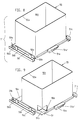
- the transport unit is to be understood as the unit of transport pallet 56 with a different number of pallets 55, which, however, always have the same outer dimensions if possible.
- signal transmitters 60 are arranged on the profile skeleton 54a, the number of which is the largest possible Number of pallets in the transport unit T, T 'and their mutual distance corresponds to a pallet 55 of the lowest height.
- there is a bar code 55k on the pallets 55 so that the type of the pallet can be scanned by a reading sensor 61 arranged at the filling station Fs and it can thus be ensured that the receiving troughs 55g of the pallets also match the molded parts 63.
- the transport pallet itself consists of two guide rails 56b which are connected to one another by a cross piece 56c (in the specific exemplary embodiment a cross plate).
- This basic element already has a support profile which corresponds to the support profile of the injection mold 14a, 14b.
- the cross-sectional profile of the guide rails also corresponds to the cross-sectional profile of the contact plates 14a ', 14b' of the injection mold to be transported on the transport vehicle when changing the mold.
- a transport vehicle F (indicated only schematically in the drawing in FIG. 2) is already known from DE 36 17 094. This transport vehicle is intended to transport injection molds or transport units and thus opens up significant rationalization options for the transport system of the injection molding machine.
- a takeover device for the transport vehicle can actively remove the transport unit from the pallet tower or insert it into the rear or the side thereof.
- Another embodiment is of course also conceivable, in which the transport vehicle itself passively takes over the corresponding transport units.
- transverse grooves 56a are therefore already arranged on the guide rails 56b, into which a driver of a transport chain of the transport vehicle F can be steered.
- the basic element made of sheet metal by folding and punching, consisting of coherent guide rails and cross plate, is already prepared for modular upgrading.
- connecting elements 56d are therefore provided, if necessary vertical support elements 56e can be connected.
- the number of pallet guides 59 required depending on the pallet height can then be attached at any height of these support elements 56e, which allows great flexibility with regard to the pallet sizes.
- both the pallet guides 59 and the pallet guides 58 have angled end regions 59b, which allow easy transfer from the pallet tower to the filling station and vice versa.
- the bottom 55a which has the depressions 55g, is enclosed by a vertical protective wall 55f.
- the base area of the bottom 55a is, as shown in FIGS. 11-15 recognizable, smaller than the floor plan of the protective wall. This ensures a basic stackability of the pallets.
- the pallets With the centering area 55d, the pallets rest on the support plates 51.
- recesses 51b are provided in the support plates 51, which correspond to the respective centering area. Nevertheless, the pallets 55 can be stacked in a space-saving manner outside the pallet tower and the transport unit. The pallet is therefore not itself supported directly on the transport pallet 56, but indirectly via the support plate 51, the contour 51b 'of the recess 51b of the support plate corresponding to the upper edge 55m of a pallet 55.
- coding lugs 51c which are recognized by the signal generators 60, can be provided on the support plate 51 to identify the pallets or to identify the pallet height located in a transport unit. To this end the slide rail 51e is also slightly set back in its edge regions.
- the filling station arranged within the layout of the injection molding machine in the variant according to FIGS. 1-3 can be easily converted into the variant according to FIGS. 4,5 are converted, in which the filling station is outside the outline of the injection molding machine.
- the filling station lies in front of that end face of the injection molding machine that is adjacent to the mold clamping unit W.
- the assembly effort is essentially limited to the fact that instead of the pallet guide 58, an endless conveyor belt 18 is inserted into the injection molding machine at the same height level, so that the injection parts 63 can be placed directly on the conveyor belt.
- the pallet guide 58 is located approximately in the same horizontal plane e-e (FIG. 3) as the conveying surface of the conveyor belt, the height of this plane being approximately the height of the upper edge of the injection mold 14a, 14b.
- the pallets are individually supported in the transport unit, the pallets can be pulled out of the respective transport unit without any problems, the comparison being obvious with drawers which are pulled out of a cabinet. Because, like in a cabinet, the drawers can be pushed out and in individually independently of one another and in any order, the possibility also arises here of processing the pallets in any order, preferably being worked from top to bottom or from bottom to top.
- the filling is such that a pallet is first pulled out of the transport unit T, T ', then filled in the filling station Fs and then returned to the same place in the transport unit.
- the elevator is then lowered or raised until the next pallet is in the ready position.
- the entire elevator can move freely vertically, since there are no disruptive connecting elements or even Pallet parts remain in the movement space required for vertical movement.
- a filled transport unit can be easily removed and an empty transport unit can be transferred while a pallet is being filled.
- This vertical possibility of movement does not matter whether the transport vehicle itself is prepared for this, for example by means of a lifting device, to take over the transport units at any height. Rather, the transport vehicle F does not have to have any lifting device at all, since the elevator has enough time to transfer the filled transport unit to a transfer level for the transport vehicle.
Landscapes
- Engineering & Computer Science (AREA)
- Manufacturing & Machinery (AREA)
- Mechanical Engineering (AREA)
- Injection Moulding Of Plastics Or The Like (AREA)
- Pallets (AREA)
- Moulds For Moulding Plastics Or The Like (AREA)
- Encapsulation Of And Coatings For Semiconductor Or Solid State Devices (AREA)
- Processing And Handling Of Plastics And Other Materials For Molding In General (AREA)
Claims (10)
- Dispositif de transport pour l'évacuation d'articles injectés (65) d'une presse d'injection de matière plastique, à l'aide de palettes (55) qui, après avoir été enlevées d'une tour de palettes (54), sont remplies dans un poste de remplissage (Fs) dans la région de la presse d'injection puis sont transférées en retour du poste de remplissage dans la tour de palettes, qui présente au moins un élévateur (53), déplaçable sur des éléments d'ossature (54a'), librement mobile en cas de besoin pendant le processus de remplissage et destiné à recevoir au moins deux unités de transport (T ; T'), les palettes (55) pouvant être, pour former les unités de transport, réunies à des palettes de transport (56) soutenues sur l'élévateur (53), caractérisé en ce que les palettes de transport (56) soutiennent individuellement les palettes (55) sur des éléments porteurs qui, selon la hauteur des palettes, portent un nombre différent de guides de palettes, et en ce que l'élévateur (53) se trouve, tant lors de l'enlèvement des palettes (55) que lors du transfert des palettes remplies (55) dans la tour de palettes (54), dans une position qui permet de transférer la palette remplie (55) au moins à la même place, dans l'unité de transport (T ; T'), où la palette (55) a été enlevée de cette unité de transport.
- Dispositif selon la revendication 1, caractérisé en ce que l'élévateur (53) peut être déplacé verticalement au moins d'un mécanisme à broche de levage (62), soutenu sur l'ossature de profilés (54a) de la tour de palettes (54) et dont l'écrou fileté (62b) fixé sur l'élévateur (53) se trouve en prise avec la broche de levage rotative (62a) de ce mécanisme à broche de levage (62), le moteur (62c) de ce mécanisme étant disposé horizontalement quasiment dans la projection verticale de l'ossature de profilés (54a) de la tour de palettes (54) et entraînant la broche de levage (62a) par l'intermédiaire d'une transmission de renvoi.
- Dispositif selon l'une des revendications précédentes, caractérisé en ce que la tour de palettes (54) est au moins deux fois plus haute que l'élévateur (53), dans lequel au moins deux unités de transport (T ; T') peuvent être reçues l'une au-dessus de l'autre et sur lequel sont prévus deux fourches réceptrices (53a) pour des unités de transport (T ; T'), fourches qui sont formées par deux rails parallèles (53a') mutuellement reliés par au moins une branche transversale (53a'').
- Dispositif selon l'une des revendications précédentes, caractérisé en ce que des transmetteurs de signaux (60) sont disposés sur l'ossature de profilés (54a) de la tour de palettes (54), transmetteurs dont le nombre correspond au nombre maximal possible de palettes dans l'unité de transport (T ; T') et dont l'écartement mutuel correspond à une palette (55) de hauteur minimale, et en ce que les palettes (55) sont pourvues en cas de besoin d'un code barres (55k) qui est lu par des capteurs de lecture (61) disposés sur le poste de remplissage.
- Dispositif selon l'une des revendications précédentes, caractérisé en ce que les unités de transport (T ; T') peuvent, au moyen d'un dispositif de remise, être respectivement sorties de la tour de palettes (54) ou rentrées dans cette dernière par l'arrière, respectivement pour les remettre à un moyen de transport ou pour les recevoir de ce dernier, le moyen de transport étant un chariot de transport (F) conçu pour le transport de moules d'injection (14a, 14b), et en ce que les palettes de transport (56) présentent chacune un profilé d'appui reproduisant le profilé d'appui du moule d'injection (14a, 14b) de la presse d'injection de matière plastique.
- Dispositif selon la revendication 5, caractérisé en ce que le chariot de transport (F) est pourvu du dispositif de remise, par lequel une unité de transport (T ; T') peut être tirée hors de la tour de palettes (54) ou, selon le cas, poussée dans cette dernière par l'arrière ou par le côté, par le fait qu'au moins une rainure transversale respective (56a) est disposée sur au moins un rail de guidage (56b) de la palette de transport (56), rainure dans laquelle peut être guidé un entraîneur d'une chaîne de transport du chariot de transport.
- Unité de transport, notamment pour l'évacuation d'articles injectés d'un dispositif selon les revendications 1 à 6, qui est constituée d'une palette de transport (56) et d'au moins une palette (55) réunie en cas de besoin à la palette de transport, la palette (55) pouvant être séparée de l'unité de transport afin de remplir cette palette des articles injectés provenant de la presse d'injection, caractérisée en ce que la palette de transport (56) présente des éléments porteurs (56e) qui sont prévus pour le raccordement d'un nombre différent, selon la hauteur des palettes, de guides de palettes (59) qui soutiennent individuellement les palettes (55).
- Unité de transport selon la revendication 7, caractérisée en ce que les éléments porteurs (56e) sont verticaux et peuvent, en cas de besoin, être retirés de la palette de transport (56) au niveau d'éléments de raccordement (56d) de la palette de transport.
- Unité de transport selon la revendication 7 ou 8, caractérisée en ce que la palette (55) est elle-même maintenue dans une plaque d'appui (51), qui est guidée sur les guides de palettes (59) de la palette de transport (56) qui sont fixés sur les éléments porteurs verticaux (56e) qui se dressent librement, la plaque d'appui (51) présentant l'élément d'accouplement (51a) pour la broche d'entraînement (57a) de la chaîne (57b) du mécanisme d'entraînement (57).
- Unité de transport selon l'une des revendications 7 à 9, caractérisée en ce que les palettes de transport (56) présentent chacune un profilé d'appui reproduisant le profilé d'appui du moule d'injection (14a, 14b) de la presse d'injection de matière plastique, profilé qui est formé par deux rails de guidage parallèles (56b) mutuellement reliés par au moins une branche transversale (56c), rails dont le profil de section correspond au profil de section des plaques d'application (14a', 14b') d'un moule d'injection (14a, 14b) à transporter lors du changement de moule sur un chariot de transport (F) conçu à cet effet, au moins une rainure transversale respective (56a) étant disposée sur au moins un rail de guidage (56b) de la palette de transport (56), rainure dans laquelle peut être guidé un entraîneur d'une chaîne de transport du chariot de transport.
Applications Claiming Priority (4)
| Application Number | Priority Date | Filing Date | Title |
|---|---|---|---|
| DE4120129 | 1991-06-19 | ||
| DE19914120131 DE4120131C1 (fr) | 1991-06-19 | 1991-06-19 | |
| DE4120131 | 1991-06-19 | ||
| DE19914120129 DE4120129C2 (de) | 1991-06-19 | 1991-06-19 | Vorrichtung für den Abtransport von Spritzteilen aus einer Kunststoff-Spritzgießmaschine |
Publications (3)
| Publication Number | Publication Date |
|---|---|
| EP0519318A2 EP0519318A2 (fr) | 1992-12-23 |
| EP0519318A3 EP0519318A3 (en) | 1993-05-05 |
| EP0519318B1 true EP0519318B1 (fr) | 1997-03-12 |
Family
ID=25904650
Family Applications (1)
| Application Number | Title | Priority Date | Filing Date |
|---|---|---|---|
| EP92109806A Expired - Lifetime EP0519318B1 (fr) | 1991-06-19 | 1992-06-11 | Dispositif et unité de transport pour l'évacuation d'articles injectés d'une machine à mouler par injection |
Country Status (6)
| Country | Link |
|---|---|
| US (1) | US5368466A (fr) |
| EP (1) | EP0519318B1 (fr) |
| JP (1) | JPH0775857B2 (fr) |
| AT (1) | ATE149911T1 (fr) |
| CA (1) | CA2071339A1 (fr) |
| DE (1) | DE59208157D1 (fr) |
Cited By (1)
| Publication number | Priority date | Publication date | Assignee | Title |
|---|---|---|---|---|
| DE19848334C2 (de) * | 1998-10-20 | 2001-08-16 | Karl Hehl | Spritzgießmaschine mit einem Handhabungsgerät |
Families Citing this family (12)
| Publication number | Priority date | Publication date | Assignee | Title |
|---|---|---|---|---|
| JPH0753009A (ja) * | 1993-08-12 | 1995-02-28 | Shinkawa Ltd | マガジン搬送装置 |
| DE4408537A1 (de) * | 1994-03-14 | 1995-09-21 | Leybold Ag | Vorrichtung für den Transport von Substraten |
| US5610081A (en) * | 1996-06-03 | 1997-03-11 | Taiwan Semiconductor Manufacturing Company, Ltd | Integrated circuit module fixing method for temperature cycling test |
| US5756133A (en) * | 1996-10-03 | 1998-05-26 | Warner-Lambert Company | Continuous gum base processing with cooling towers |
| US7214286B2 (en) * | 2004-01-30 | 2007-05-08 | Jarden Corporation | Stacked family molding and subsequent assembly process |
| US8438981B2 (en) | 2008-06-20 | 2013-05-14 | Oria Collapsibles, Llc | Pallet design with buoyant characteristics |
| US8167605B2 (en) * | 2008-06-20 | 2012-05-01 | Oria Collapsibles, Llc | Production assembly and process for mass manufacture of a thermoplastic pallet incorporating a stiffened insert |
| US8701569B2 (en) | 2008-06-20 | 2014-04-22 | Oria Collapsibles, Llc | Pallet design with structural reinforcement |
| US8522694B2 (en) | 2008-06-20 | 2013-09-03 | Oria Collapsibles, Llc | Structural supporting pallet construction with improved perimeter impact absorbing capabilities |
| CN110549549B (zh) * | 2019-07-10 | 2021-04-09 | 浙江锋龙电气股份有限公司 | 一种模具镶件自动化加工设备 |
| JP7358871B2 (ja) * | 2019-09-19 | 2023-10-11 | セイコーエプソン株式会社 | 射出成形システムおよび成形品の製造方法 |
| CN111231204B (zh) * | 2020-01-10 | 2021-08-31 | 滁州信达自动化设备制造有限公司 | 一种运输模具的换模小车 |
Citations (1)
| Publication number | Priority date | Publication date | Assignee | Title |
|---|---|---|---|---|
| US5032053A (en) * | 1986-04-16 | 1991-07-16 | Gesellschaft Fur Roboter Und Logistiktechnologie, Rollotec Ag | Goods handling facility and a method of operating same |
Family Cites Families (14)
| Publication number | Priority date | Publication date | Assignee | Title |
|---|---|---|---|---|
| GB1071096A (en) * | 1964-06-17 | 1967-06-07 | Mazetti Aktiebolag | Improvements relating to moulding machines |
| JPS4894165A (fr) * | 1972-03-21 | 1973-12-04 | ||
| JPS57184001A (en) * | 1981-05-06 | 1982-11-12 | Mitsubishi Metal Corp | Automatic aligning apparatus for molded articles |
| US4687403A (en) * | 1983-10-18 | 1987-08-18 | Motoda Electronics Co., Ltd. | Article delivery apparatus |
| JPS60262776A (ja) * | 1984-06-12 | 1985-12-26 | Hitachi Seiko Ltd | プリント基板のストツカ |
| US4932828A (en) * | 1985-09-04 | 1990-06-12 | Canon Kabushiki Kaisha | Automatic article feeding system |
| JPH0815937B2 (ja) * | 1986-06-23 | 1996-02-21 | 松下電器産業株式会社 | 部品収納部材の分離位置決め装置 |
| US5203661A (en) * | 1987-08-05 | 1993-04-20 | Canon Kabushiki Kaisha | Handling device for articles or containers |
| DE3830964A1 (de) * | 1988-09-12 | 1990-03-22 | Karl Hehl | Spritzgiessmaschine mit einer einrichtung zur entnahme der spritzteile aus dem spritzwerkzeug |
| GB8807666D0 (en) * | 1988-03-31 | 1988-05-05 | Wadkin Public Ltd Co | Fixture pallet changing apparatus |
| DE3830958A1 (de) * | 1988-09-12 | 1990-03-22 | Karl Hehl | Vorrichtung fuer den abtransport von spritzteilen aus einer spritzgiessmaschine |
| JPH0292512A (ja) * | 1988-09-29 | 1990-04-03 | Teijin Seiki Co Ltd | インサート成形機におけるパレット昇降機構 |
| US5104277A (en) * | 1989-04-06 | 1992-04-14 | Hewlett-Packard Company | Method and apparatus for automatically changing printed circuit board test fixtures |
| JP2864041B2 (ja) * | 1990-05-02 | 1999-03-03 | 株式会社進興製作所 | 自動パレット交換装置および自動パレット交換方法 |
-
1992
- 1992-06-11 DE DE59208157T patent/DE59208157D1/de not_active Expired - Fee Related
- 1992-06-11 AT AT92109806T patent/ATE149911T1/de not_active IP Right Cessation
- 1992-06-11 EP EP92109806A patent/EP0519318B1/fr not_active Expired - Lifetime
- 1992-06-16 CA CA002071339A patent/CA2071339A1/fr not_active Abandoned
- 1992-06-19 US US07/901,610 patent/US5368466A/en not_active Expired - Fee Related
- 1992-06-19 JP JP4186274A patent/JPH0775857B2/ja not_active Expired - Lifetime
Patent Citations (1)
| Publication number | Priority date | Publication date | Assignee | Title |
|---|---|---|---|---|
| US5032053A (en) * | 1986-04-16 | 1991-07-16 | Gesellschaft Fur Roboter Und Logistiktechnologie, Rollotec Ag | Goods handling facility and a method of operating same |
Cited By (1)
| Publication number | Priority date | Publication date | Assignee | Title |
|---|---|---|---|---|
| DE19848334C2 (de) * | 1998-10-20 | 2001-08-16 | Karl Hehl | Spritzgießmaschine mit einem Handhabungsgerät |
Also Published As
| Publication number | Publication date |
|---|---|
| DE59208157D1 (de) | 1997-04-17 |
| JPH05261760A (ja) | 1993-10-12 |
| EP0519318A2 (fr) | 1992-12-23 |
| EP0519318A3 (en) | 1993-05-05 |
| US5368466A (en) | 1994-11-29 |
| ATE149911T1 (de) | 1997-03-15 |
| JPH0775857B2 (ja) | 1995-08-16 |
| CA2071339A1 (fr) | 1992-12-20 |
Similar Documents
| Publication | Publication Date | Title |
|---|---|---|
| EP0359014B1 (fr) | Dispositif d'évacuation de pièces injectées d'une machine à mouler des matières plastiques par injection | |
| EP0519318B1 (fr) | Dispositif et unité de transport pour l'évacuation d'articles injectés d'une machine à mouler par injection | |
| DE164062T1 (de) | Vorrichtung zum wechseln einer form in einer presse, insbesondere in einer spritzgiessmaschine. | |
| DE9219137U1 (de) | Thermoformmaschine zum Herstellen von hohlen Gegenständen | |
| DE19727749A1 (de) | Seitlich einfahrender Roboter zur Entnahme von geformten Gegenständen | |
| DE69701664T2 (de) | Verfahren und Vorrichtung zum Einspritz-Streckblasformen | |
| DE2543621A1 (de) | Kannenwechseleinrichtung | |
| EP0359013B1 (fr) | Presse à mouler des matières plastiques par injection | |
| EP0195231A2 (fr) | Unité de fermeture de moule avec un dispositif de changement de moule et une table d'adaptation pour préchauffer les moules d'injection de matière plastique | |
| EP0255852B1 (fr) | Dispositif de changement de moule pour une machine d'injection de matière plastique | |
| EP0246398B1 (fr) | Dispositif de changement de moule pour un groupe de machine à injecter les matières plastiques | |
| EP0579937B1 (fr) | Machine de formage par le vide, pour former et souder, en mîme temps, deux feuilles en plastique | |
| DE102007038622A1 (de) | Stapelzelle | |
| EP0321461B1 (fr) | Installation de moulage par injection | |
| DE4120129C2 (de) | Vorrichtung für den Abtransport von Spritzteilen aus einer Kunststoff-Spritzgießmaschine | |
| DE3822363C2 (fr) | ||
| EP0703060B1 (fr) | Procédé pour décharger et déposer et/ou empiler des objets moulés emboutis et dispositif pour sa mise en oeuvre | |
| EP4149867A1 (fr) | Installation modulaire pour la production de produits alimentaires | |
| DE4137169C2 (de) | Fördereinrichtung für Stangenmaterial | |
| DE4120131C1 (fr) | ||
| DE19936600B4 (de) | Verfahren und Vorrichtung zum Wechseln eines Formwerkzeugs und zum Ersetzen einer Materialpalette bei einer Vakuumformmaschine | |
| DE4121844C2 (de) | Vorrichtung zum Aufnehmen und Abführen von Auffangkästen für Teile aus der Serienproduktion | |
| EP0890880B1 (fr) | Appareil pour le traitement de plaques d'impression | |
| DE2541620A1 (de) | Verfahren und einrichtung zum handhaben bzw. laden von behaeltern | |
| DE3644915A1 (de) | Einrichtung zum abtransport der spritzlinge an einer gruppe von kunststoff-spritzgiessmaschinen |
Legal Events
| Date | Code | Title | Description |
|---|---|---|---|
| PUAI | Public reference made under article 153(3) epc to a published international application that has entered the european phase |
Free format text: ORIGINAL CODE: 0009012 |
|
| AK | Designated contracting states |
Kind code of ref document: A2 Designated state(s): AT CH DE ES FR GB IT LI NL PT |
|
| PUAL | Search report despatched |
Free format text: ORIGINAL CODE: 0009013 |
|
| AK | Designated contracting states |
Kind code of ref document: A3 Designated state(s): AT CH DE ES FR GB IT LI NL PT |
|
| 17P | Request for examination filed |
Effective date: 19931103 |
|
| 17Q | First examination report despatched |
Effective date: 19950628 |
|
| GRAG | Despatch of communication of intention to grant |
Free format text: ORIGINAL CODE: EPIDOS AGRA |
|
| GRAH | Despatch of communication of intention to grant a patent |
Free format text: ORIGINAL CODE: EPIDOS IGRA |
|
| GRAH | Despatch of communication of intention to grant a patent |
Free format text: ORIGINAL CODE: EPIDOS IGRA |
|
| GRAA | (expected) grant |
Free format text: ORIGINAL CODE: 0009210 |
|
| AK | Designated contracting states |
Kind code of ref document: B1 Designated state(s): AT CH DE ES FR GB IT LI NL PT |
|
| PG25 | Lapsed in a contracting state [announced via postgrant information from national office to epo] |
Ref country code: NL Free format text: LAPSE BECAUSE OF FAILURE TO SUBMIT A TRANSLATION OF THE DESCRIPTION OR TO PAY THE FEE WITHIN THE PRESCRIBED TIME-LIMIT Effective date: 19970312 Ref country code: ES Free format text: THE PATENT HAS BEEN ANNULLED BY A DECISION OF A NATIONAL AUTHORITY Effective date: 19970312 |
|
| REF | Corresponds to: |
Ref document number: 149911 Country of ref document: AT Date of ref document: 19970315 Kind code of ref document: T |
|
| REG | Reference to a national code |
Ref country code: CH Ref legal event code: EP |
|
| REG | Reference to a national code |
Ref country code: CH Ref legal event code: NV Representative=s name: LUCHS & PARTNER PATENTANWAELTE |
|
| REF | Corresponds to: |
Ref document number: 59208157 Country of ref document: DE Date of ref document: 19970417 |
|
| ITF | It: translation for a ep patent filed | ||
| PG25 | Lapsed in a contracting state [announced via postgrant information from national office to epo] |
Ref country code: PT Effective date: 19970612 |
|
| ET | Fr: translation filed | ||
| NLV1 | Nl: lapsed or annulled due to failure to fulfill the requirements of art. 29p and 29m of the patents act | ||
| GBT | Gb: translation of ep patent filed (gb section 77(6)(a)/1977) |
Effective date: 19970714 |
|
| PLBE | No opposition filed within time limit |
Free format text: ORIGINAL CODE: 0009261 |
|
| STAA | Information on the status of an ep patent application or granted ep patent |
Free format text: STATUS: NO OPPOSITION FILED WITHIN TIME LIMIT |
|
| 26N | No opposition filed | ||
| PGFP | Annual fee paid to national office [announced via postgrant information from national office to epo] |
Ref country code: GB Payment date: 19980527 Year of fee payment: 7 |
|
| PGFP | Annual fee paid to national office [announced via postgrant information from national office to epo] |
Ref country code: FR Payment date: 19980617 Year of fee payment: 7 |
|
| PGFP | Annual fee paid to national office [announced via postgrant information from national office to epo] |
Ref country code: AT Payment date: 19980623 Year of fee payment: 7 |
|
| PGFP | Annual fee paid to national office [announced via postgrant information from national office to epo] |
Ref country code: CH Payment date: 19980701 Year of fee payment: 7 |
|
| PG25 | Lapsed in a contracting state [announced via postgrant information from national office to epo] |
Ref country code: GB Free format text: LAPSE BECAUSE OF NON-PAYMENT OF DUE FEES Effective date: 19990611 Ref country code: AT Free format text: LAPSE BECAUSE OF NON-PAYMENT OF DUE FEES Effective date: 19990611 |
|
| PG25 | Lapsed in a contracting state [announced via postgrant information from national office to epo] |
Ref country code: LI Free format text: LAPSE BECAUSE OF NON-PAYMENT OF DUE FEES Effective date: 19990630 Ref country code: FR Free format text: THE PATENT HAS BEEN ANNULLED BY A DECISION OF A NATIONAL AUTHORITY Effective date: 19990630 Ref country code: CH Free format text: LAPSE BECAUSE OF NON-PAYMENT OF DUE FEES Effective date: 19990630 |
|
| GBPC | Gb: european patent ceased through non-payment of renewal fee |
Effective date: 19990611 |
|
| REG | Reference to a national code |
Ref country code: CH Ref legal event code: PL |
|
| REG | Reference to a national code |
Ref country code: FR Ref legal event code: ST |
|
| PGFP | Annual fee paid to national office [announced via postgrant information from national office to epo] |
Ref country code: DE Payment date: 20010410 Year of fee payment: 10 |
|
| PG25 | Lapsed in a contracting state [announced via postgrant information from national office to epo] |
Ref country code: DE Free format text: LAPSE BECAUSE OF NON-PAYMENT OF DUE FEES Effective date: 20030101 |
|
| PG25 | Lapsed in a contracting state [announced via postgrant information from national office to epo] |
Ref country code: IT Free format text: LAPSE BECAUSE OF NON-PAYMENT OF DUE FEES Effective date: 20050611 |