EP0519674A2 - Tête magnétorésistive laminée - Google Patents
Tête magnétorésistive laminée Download PDFInfo
- Publication number
- EP0519674A2 EP0519674A2 EP92305493A EP92305493A EP0519674A2 EP 0519674 A2 EP0519674 A2 EP 0519674A2 EP 92305493 A EP92305493 A EP 92305493A EP 92305493 A EP92305493 A EP 92305493A EP 0519674 A2 EP0519674 A2 EP 0519674A2
- Authority
- EP
- European Patent Office
- Prior art keywords
- magneto
- resistive
- head
- magnetic
- heads
- Prior art date
- Legal status (The legal status is an assumption and is not a legal conclusion. Google has not performed a legal analysis and makes no representation as to the accuracy of the status listed.)
- Granted
Links
Images


Classifications
-
- G—PHYSICS
- G11—INFORMATION STORAGE
- G11B—INFORMATION STORAGE BASED ON RELATIVE MOVEMENT BETWEEN RECORD CARRIER AND TRANSDUCER
- G11B5/00—Recording by magnetisation or demagnetisation of a record carrier; Reproducing by magnetic means; Record carriers therefor
- G11B5/127—Structure or manufacture of heads, e.g. inductive
- G11B5/33—Structure or manufacture of flux-sensitive heads, i.e. for reproduction only; Combination of such heads with means for recording or erasing only
- G11B5/39—Structure or manufacture of flux-sensitive heads, i.e. for reproduction only; Combination of such heads with means for recording or erasing only using magneto-resistive devices or effects
- G11B5/3903—Structure or manufacture of flux-sensitive heads, i.e. for reproduction only; Combination of such heads with means for recording or erasing only using magneto-resistive devices or effects using magnetic thin film layers or their effects, the films being part of integrated structures
- G11B5/3906—Details related to the use of magnetic thin film layers or to their effects
- G11B5/3916—Arrangements in which the active read-out elements are coupled to the magnetic flux of the track by at least one magnetic thin film flux guide
- G11B5/3919—Arrangements in which the active read-out elements are coupled to the magnetic flux of the track by at least one magnetic thin film flux guide the guide being interposed in the flux path
- G11B5/3922—Arrangements in which the active read-out elements are coupled to the magnetic flux of the track by at least one magnetic thin film flux guide the guide being interposed in the flux path the read-out elements being disposed in magnetic shunt relative to at least two parts of the flux guide structure
- G11B5/3925—Arrangements in which the active read-out elements are coupled to the magnetic flux of the track by at least one magnetic thin film flux guide the guide being interposed in the flux path the read-out elements being disposed in magnetic shunt relative to at least two parts of the flux guide structure the two parts being thin films
-
- G—PHYSICS
- G11—INFORMATION STORAGE
- G11B—INFORMATION STORAGE BASED ON RELATIVE MOVEMENT BETWEEN RECORD CARRIER AND TRANSDUCER
- G11B5/00—Recording by magnetisation or demagnetisation of a record carrier; Reproducing by magnetic means; Record carriers therefor
- G11B5/127—Structure or manufacture of heads, e.g. inductive
- G11B5/33—Structure or manufacture of flux-sensitive heads, i.e. for reproduction only; Combination of such heads with means for recording or erasing only
- G11B5/39—Structure or manufacture of flux-sensitive heads, i.e. for reproduction only; Combination of such heads with means for recording or erasing only using magneto-resistive devices or effects
- G11B5/3903—Structure or manufacture of flux-sensitive heads, i.e. for reproduction only; Combination of such heads with means for recording or erasing only using magneto-resistive devices or effects using magnetic thin film layers or their effects, the films being part of integrated structures
- G11B5/3906—Details related to the use of magnetic thin film layers or to their effects
- G11B5/3945—Heads comprising more than one sensitive element
- G11B5/3948—Heads comprising more than one sensitive element the sensitive elements being active read-out elements
- G11B5/3951—Heads comprising more than one sensitive element the sensitive elements being active read-out elements the active elements being arranged on several parallel planes
-
- G—PHYSICS
- G11—INFORMATION STORAGE
- G11B—INFORMATION STORAGE BASED ON RELATIVE MOVEMENT BETWEEN RECORD CARRIER AND TRANSDUCER
- G11B5/00—Recording by magnetisation or demagnetisation of a record carrier; Reproducing by magnetic means; Record carriers therefor
- G11B5/127—Structure or manufacture of heads, e.g. inductive
- G11B5/33—Structure or manufacture of flux-sensitive heads, i.e. for reproduction only; Combination of such heads with means for recording or erasing only
- G11B5/39—Structure or manufacture of flux-sensitive heads, i.e. for reproduction only; Combination of such heads with means for recording or erasing only using magneto-resistive devices or effects
- G11B5/3903—Structure or manufacture of flux-sensitive heads, i.e. for reproduction only; Combination of such heads with means for recording or erasing only using magneto-resistive devices or effects using magnetic thin film layers or their effects, the films being part of integrated structures
- G11B5/3967—Composite structural arrangements of transducers, e.g. inductive write and magnetoresistive read
- G11B5/397—Composite structural arrangements of transducers, e.g. inductive write and magnetoresistive read with a plurality of independent magnetoresistive active read-out elements for respectively transducing from selected components
- G11B5/3977—Composite structural arrangements of transducers, e.g. inductive write and magnetoresistive read with a plurality of independent magnetoresistive active read-out elements for respectively transducing from selected components from different information tracks
-
- G—PHYSICS
- G11—INFORMATION STORAGE
- G11B—INFORMATION STORAGE BASED ON RELATIVE MOVEMENT BETWEEN RECORD CARRIER AND TRANSDUCER
- G11B5/00—Recording by magnetisation or demagnetisation of a record carrier; Reproducing by magnetic means; Record carriers therefor
- G11B5/48—Disposition or mounting of heads or head supports relative to record carriers ; arrangements of heads, e.g. for scanning the record carrier to increase the relative speed
- G11B5/488—Disposition of heads
- G11B5/4893—Disposition of heads relative to moving tape
Definitions
- the present invention relates to a lamination type magneto-resistive head used for a magnetic recording/reproducing apparatus.
- a magneto-resistive head has come to attract the attention in compliance with the trend to a higher recording density, higher data transfer speed an multi-channel in the magnetic recording/reproducing apparatus.
- magneto-resistive heads are being used of which reproduced outputs are independent of the speed.
- Fig. 6 (a) and (b) show a conventional magneto-resistive head.
- Fig. 6(a) is a perspective view of the main area and
- Fig. 6(b) is a sectional drawing shown at a section I-I′ of Fig. 6(a).
- the conventional magneto-resistive head is formed with a first magnetic layer 27 composed of Permalloy, Sendust or amorphous magnetic materials, etc.
- a bias conductor 22 composed of a conductive material such as gold thin film or copper thin film which is a means of applying a bias magnetic field to magneto-resistive element 23
- a magneto-resistive element 23 comprised of Permalloy thin film
- electrodes 24a and 24b formed of the gold thin film or copper thin film for running a driving current to the magneto-resistive element 23
- a second magnetic layer 25 and a third magnetic layer 26 composed of soft magnetic material through such an insulating layer 32 as SiO2 or the like together with a first gap 28 and a second gap 29 consecutively.
- a protection layer 31 is formed and finally a cover plate 30 is bonded, thereby completing the magneto-resistive head.
- said magneto-resistive element 23 is formed in such a manner that said magneto-resistive element 23 overlaps each edge of the second magnetic layer 25 and the third magnetic layer 26.
- the first gap 28 which conducts into the magnetic head a recording magnetic field generated from a magnetic recording medium is formed between the first and second magnetic layers 27 and 25.
- the surface 33 is the sliding surface of magnetic medium.
- a lamination type magneto-resistive head 80 as shown in Fig. 7 is known.
- This is the same structure as that of the conventional example, and the first magneto-resistive type head 81a and the second magneto-resistive type head 81b which are different in track width from each other are consecutively laminated on a common substrate through a separate layer 83 so that the second magnetic gap 29a of the first magneto-resistive head 81a faces with the first magnetic layer 27b of the second magneto-resistive type head 81b each other.
- each magneto-resistive head has a different reproducing track width, allowing a plurality of track formats having a different track width to be conformed. That is, the magneto-resistive head 81b is used for the one track format, while the 81a is used for the other one.
- the magneto-resistive element 23a on the first magneto-resistive type head 81a is faced with the first magnetic layer 27b of the second magneto-resistive type head 81b, and the first magnetic layer 27b of the second magneto-resistive type head 81b acts as a magnetic shield to the first magneto-resistive head, thereby preventing the signal magnetic field generated from the magnetic recording medium from flowing into the first magneto-resistive head.
- an object of the present invention is to provide easily at low cost a lamination type magneto-resistive head having a stable reproduction frequency characteristics and capable of conforming to a plurality of track formats which are different from one another in track width and/or the number of channels.
- the lamination type magneto-resistive head of the present invention is to make one integrated structure by combining two magneto-resistive heads, each of which has in a magnetic circuit a first gap for introducing into a magnetic head a signal magnetic field generated from a magnetic recording medium, a magneto-resistive element, a second gap arranged in the vicinity of the magneto-resistive element for introducing said signal magnetic field into the magneto-resistive element, and a bias magnetic field application means for applying the bias magnetic field to said magneto-resistive element, said magneto-resistive heads having respective first magnetic layers which face with each other.
- the lamination type magneto-resistive head of the present invention allows a plurality of track formats having different track widths and/or different numbers of channels from one another to be conformed based on the above-mentioned structure, thus giving stable frequency characteristics of the reproducing output because of no magnetic interference given to the magneto-resistive element area of laminated magneto-resistive head from another magneto-resistive head.
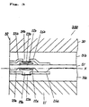
- Fig. 1 illustrates a cross-sectional view of a lamination type magneto-resistive head showing the first embodiment of the present invention.
- Fig. 2 illustrates a cross-sectional view of a lamination type magneto-resistive head showing the second embodiment of the present invention.
- Fig. 3 illustrates a cross-sectional view of a lamination type magneto-resistive head showing the third embodiment of the present invention.
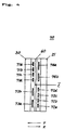
- Fig. 4 illustrates a general view of a multi-channel lamination type magneto-resistive head as seen from the contact surface of magnetic recording medium, showing the fourth embodiment of the present invention.
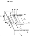
- Fig. 5 (a) and (b) illustrate views of two kinds of track formats which conform to a multi-channel lamination type magneto-resistive head of the fourth embodiment.
- Fig. 6(a) illustrates a general view of the main area of a conventional magneto-resistive head.
- Fig. 6(b) illustrates a cross-sectional view of I-I′ of Fig. 6(a).
- Fig. 7 illustrates a cross-sectional view of the conventional lamination type magneto-resistive head.
- Fig. 1 illustrates the embodiment of the present invention, showing a cross-sectional structure drawing similar to the one illustrated in Fig. 6(b).
- the lamination type magneto-resistive head 100 in the embodiment of the present invention is composed of a lamination of the first and second magneto-resistive heads 101a and 101b made consecutively through an aluminum thin film 110. Namely, after forming a backing layer 131a like alumina, etc. on a substrate 121 composed of glass or ceramics, the second magnetic layer 125a composed of Permalloy or Sendust or amorphous magnetic materials, etc., and the third magnetic layer 126a are formed together with the second gap 129a.
- a magneto-resistive element 123a composed of a Permalloy thin film
- a bias conductor 122a composed of conductive materials such as gold thin film or copper thin film as means of applying a bias magnetic field to said magneto-resistive element 123a
- the first magnetic layer 127a which is composed of Permalloy, Sendust or amorphous magnetic materials, etc. and formed together with the gap 128a consecutively through an insulating layer 133 a such as SiO2, etc., thus becoming the first magneto-resistive head 101a.
- said magneto-resistive element 123a is formed in the vicinity of the second gap 129a situated between the second magnetic layer 125a and third magnetic layer 126a, in such a manner that said magneto-resistive element 123a overlaps the ends of the second magnetic layer 125a and of the third magnetic layer 126a each other.
- an intermediate layer 110 of alumina thin film, etc. is formed, and then the first magnetic layer 127b of the second magneto-resistive head 101b , the second magnetic layer 125b and the third magnetic layer 126b, the first gap 128b, the second magnetic gap 129b, bias conductor 122b, magneto-resistive element 123b, and protection layer 131b, etc. are formed through an insulating layer 133b, etc. in an approximately reverse order of structuring the first magneto-resistive head 101a.
- the second magneto-resistive head is formed in such a manner that its track width differs from that of the first magneto-resistive head, so that the widths of the first magnetic layer 127b, second magnetic layer 125b and third magnetic layer 126b are formed in such a way that they differ from that of the first magneto-resistive head.
- a cover plate 130 is bonded, followed by polishing of the magnetic medium sliding surface 132 so that the first gap 128a and 128b are exposed, thus completing the lamination type magnetic head 100.
- the lamination type thin film magnetic head of the embodiment of the present invention allows a plurality of track formats having a different track width to be conformed.
- a magneto-resistive head is used of which track width conforms to the width of one track format, while at that time a magneto-resistive head of another one is used. Furthermore, in case of this embodiment, it is structured that the first magnetic layers 127a and 127b of two magneto-resistive heads 101a and 101b are laminated by being faced with each other, magneto-resistive elements 123a and 124b do not face with other magnetic layers 127a and 127b each other. Therefore, the first magnetic layer of another magneto-resistive head does not act as a shield of another magneto-resistive head, thus providing the possible effect of stable reproducible output up to a low frequency range.
- Fig. 2 illustrates the second embodiment of the present invention.
- the same numbers are applied to the same structural elements as the ones used in the first embodiment.
- the lamination type magneto-resistive head 200 of the second embodiment is structured by lamination two magneto-resistive heads 201a and 201b in the same manner as used in the first embodiment.
- the formed position of magneto-resistive element 123a of magneto-resistive head 201a is different from that used in the first embodiment. That is, the magneto-resistive element 123a is situated on a flat alumina layer 131a which is formed on the substrate 121.
- magneto-resistive elements are subjected to noise generation and lowering in reproducible output when the flatness of backing surface became worse. Therefore, the magneto-resistive element of the present embodiment has an effect not subject to the influence of a difference in the backing surface level and allows stable reproducible characteristics to be obtained with a few noises.
- Fig. 3 illustrates the third embodiment of the present invention.
- the present embodiment is a lamination type magneto-resistive head 350 , in which in the second embodiment the first magnetic layer of each magneto-resistive head is made common each other, and thereby made a common magnetic layer 51.
- Fig. 4 illustrates the fourth embodiment as seen from the sliding surface of the magnetic medium.
- the multi-channel lamination type magneto-resistive head 70 of the present embodiment is structured by at first arranging 4 pieces of magneto-resistive heads 71a (72a), 71b (72b), 71c (72c), and 71d (72d) having a certain track width, and also two pieces of magneto-resistive heads 73a, (74a) and 73b (74b) having a different track width in a track width direction, thus making a multi-channel type, followed by laminating 2 pieces thereof so as to have a common magnetic layer 60 which is made common each other.
- the positions of magneto-resistive heads having the same track width are such that heads 71a, 71b, 71c and 71d and heads 72a, 72b, 72c and 72d or heads 73a and 73b and heads 74a and 74b are arranged in a rotation symmetry with respect to an axis Z as seen from the sliding surface of magnetic medium, thus conforming to a magnetic recording medium which runs forward and backward.
- Fig. 5(A) and (B) show track formats on 2 kinds of magnetic recording media conformable to this case.
- a total of 4 tracks of track formats shown in Fig. 5(A) are situated on each side of magnetic medium, bringing about reproduction during running forward and backward.
- the track formats shown in Fig. 5(b) are situated with 2 tracks on each side of the magnetic recording medium, bringing about reproduction.
- the multi-channel lamination type magneto-resistive head 70 is the fourth embodiment, which enables 2 kinds of track formats of reciprocally running magnetic recording medium to be conformed, providing stable reproducing outputs up to a low frequency range.
- the magnetic medium first makes contact with a common magnetic layer 60 of operating magneto-resistive head, and then contact with the first gap and the second magnetic layer.
- the positional relation-ship between the magnetic medium and the multi-channel lamination type magneto-resistive head is always constant, and reproduced outputs are independent of a running direction, thereby providing a stable output effect up to a low frequency range because of no magnetic interference given from another magneto-resistive head.
- the lamination type magneto-resistive head of the present invention conform to a plurality of track formats which are different from one another in track width and/or the number of channels, having such an effect that reproducing outputs become stable for a full frequency range, because the inadequate resistive element of the lamination type magneto-resistive head is not subjected to the interference given from another first magnetic layer.
- the first magnetic layer By making the first magnetic layer common, it eliminates the need for forming an intermediate layer and will further reduce the formation of a magnetic layer, thereby pocessing such effects that it remarkably shorten the production process and easily provide a lamination type magneto-resistive head at low cost.
- laminating 2 sets of plural magneto-resistive heads having the same track width arranged on one plane provides an effect which enables a plurality of multi-channel tracks formats to be conformed.
Landscapes
- Engineering & Computer Science (AREA)
- Manufacturing & Machinery (AREA)
- Magnetic Heads (AREA)
Applications Claiming Priority (3)
| Application Number | Priority Date | Filing Date | Title |
|---|---|---|---|
| JP148473/91 | 1991-06-20 | ||
| JP3148473A JPH04370511A (ja) | 1991-06-20 | 1991-06-20 | 積層型磁気抵抗ヘッド |
| US07/902,580 US5335127A (en) | 1991-06-20 | 1992-06-22 | Lamination type magneto-resistive head |
Publications (3)
| Publication Number | Publication Date |
|---|---|
| EP0519674A2 true EP0519674A2 (fr) | 1992-12-23 |
| EP0519674A3 EP0519674A3 (en) | 1994-06-22 |
| EP0519674B1 EP0519674B1 (fr) | 1997-04-16 |
Family
ID=26478662
Family Applications (1)
| Application Number | Title | Priority Date | Filing Date |
|---|---|---|---|
| EP92305493A Expired - Lifetime EP0519674B1 (fr) | 1991-06-20 | 1992-06-16 | Tête magnétorésistive laminée |
Country Status (3)
| Country | Link |
|---|---|
| US (1) | US5335127A (fr) |
| EP (1) | EP0519674B1 (fr) |
| JP (1) | JPH04370511A (fr) |
Cited By (4)
| Publication number | Priority date | Publication date | Assignee | Title |
|---|---|---|---|---|
| US5508868A (en) * | 1993-01-25 | 1996-04-16 | Read-Rite Corporation | Dual element magnetoresistive sensing head having in-gap flux guide and flux closure piece with particular connection of magnetoresistive sensing elements to differential amplifier |
| WO1996030897A3 (fr) * | 1995-03-24 | 1997-01-16 | Philips Electronics Nv | Tete magnetique et systeme de commande de la position d'une tete magnetique |
| WO1997033274A1 (fr) * | 1996-03-08 | 1997-09-12 | Philips Electronics N.V. | Tete magnetique multicanaux |
| US7453671B1 (en) * | 2005-10-31 | 2008-11-18 | Stoarge Technology Corporation | Magnetic head having a pair of magneto-resistive (MR) readers of the same type with each reader being tuned differently |
Families Citing this family (14)
| Publication number | Priority date | Publication date | Assignee | Title |
|---|---|---|---|---|
| EP0818038B1 (fr) * | 1996-01-31 | 2003-06-18 | Koninklijke Philips Electronics N.V. | Tete magnetique pourvue d'un detecteur magnetoresistif et dispositif de balayage pourvu de ladite tete magnetique |
| JPH09251622A (ja) * | 1996-03-18 | 1997-09-22 | Toshiba Corp | 磁気ヘッド |
| KR100233669B1 (ko) * | 1996-11-01 | 2000-01-15 | 윤종용 | 트랙 쉬프트량 보상을 위한 서보버스트 기록방법및 서보제어방법 |
| US6104562A (en) * | 1997-04-03 | 2000-08-15 | International Business Machines Corporation | Multiple element transducer for magnetic recording |
| US6404191B2 (en) * | 1997-08-08 | 2002-06-11 | Nve Corporation | Read heads in planar monolithic integrated circuit chips |
| JP2002216325A (ja) * | 2001-01-17 | 2002-08-02 | Hitachi Ltd | 複合型磁気ヘッド、これを用いた磁気ディスク装置及び磁気ディスク装置の制御方法 |
| US6646830B2 (en) * | 2001-06-07 | 2003-11-11 | International Business Machines Corporation | Monolithic magnetic read-while-write head apparatus and method of manufacture |
| JP2003338012A (ja) * | 2002-05-15 | 2003-11-28 | Sony Corp | 磁気記録ヘッド装置、磁気再生ヘッド装置及び磁気ヘッド装置並びにこれらを用いたテープドライブ装置及びディスクドライブ装置 |
| US6970331B1 (en) * | 2002-08-20 | 2005-11-29 | Storage Technology Corporation | Magnetic recording head having modules with opposing read elements and opposing periodic structures |
| US7298586B1 (en) * | 2004-09-07 | 2007-11-20 | Storage Technology Corporation | Thin-film read element with multiple read sensors |
| US7656610B1 (en) * | 2006-03-27 | 2010-02-02 | Storage Technology Corporation | Bi-directional magnetic recording head built on a common substrate |
| US8130067B2 (en) | 2010-05-11 | 2012-03-06 | Texas Instruments Incorporated | High frequency semiconductor transformer |
| US9431039B1 (en) * | 2013-05-21 | 2016-08-30 | Western Digital (Fremont), Llc | Multiple sensor array usable in two-dimensional magnetic recording |
| US9111557B2 (en) * | 2013-10-04 | 2015-08-18 | Seagate Technology Llc | Electrically insulating magnetic material for a read head |
Family Cites Families (10)
| Publication number | Priority date | Publication date | Assignee | Title |
|---|---|---|---|---|
| US4195323A (en) * | 1977-09-02 | 1980-03-25 | Magnex Corporation | Thin film magnetic recording heads |
| US4616281A (en) * | 1982-03-10 | 1986-10-07 | Copal Company Limited | Displacement detecting apparatus comprising magnetoresistive elements |
| CA1209260A (fr) * | 1982-10-29 | 1986-08-05 | Tetsuo Sekiya | Transducteur magnetique agissant par magnetoresistance |
| JPS61107520A (ja) * | 1984-10-31 | 1986-05-26 | Sony Corp | 多チヤンネル磁気抵抗効果型磁気ヘツド |
| JPS62145527A (ja) * | 1985-12-18 | 1987-06-29 | Sharp Corp | 複合型薄膜磁気ヘツド |
| JPH01303617A (ja) * | 1988-05-31 | 1989-12-07 | Matsushita Electric Ind Co Ltd | 薄膜磁気ヘッド |
| NL8902570A (nl) * | 1989-10-17 | 1991-05-16 | Philips Nv | Dunnefilm magneetkop. |
| JPH03250411A (ja) * | 1990-02-28 | 1991-11-08 | Matsushita Electric Ind Co Ltd | 複合型薄膜磁気ヘッド |
| EP0519182B1 (fr) * | 1991-04-22 | 1997-02-12 | Sharp Kabushiki Kaisha | Tête magnétique à films minces combinée |
| US5212611A (en) * | 1991-07-16 | 1993-05-18 | Storage Technology Corporation | Integral read/write recording head with dual gap dimension |
-
1991
- 1991-06-20 JP JP3148473A patent/JPH04370511A/ja active Pending
-
1992
- 1992-06-16 EP EP92305493A patent/EP0519674B1/fr not_active Expired - Lifetime
- 1992-06-22 US US07/902,580 patent/US5335127A/en not_active Expired - Fee Related
Cited By (6)
| Publication number | Priority date | Publication date | Assignee | Title |
|---|---|---|---|---|
| US5508868A (en) * | 1993-01-25 | 1996-04-16 | Read-Rite Corporation | Dual element magnetoresistive sensing head having in-gap flux guide and flux closure piece with particular connection of magnetoresistive sensing elements to differential amplifier |
| WO1996030897A3 (fr) * | 1995-03-24 | 1997-01-16 | Philips Electronics Nv | Tete magnetique et systeme de commande de la position d'une tete magnetique |
| US5966276A (en) * | 1995-03-24 | 1999-10-12 | Draaisma; Eeltje A. | Magnetic head and system for controlling the position of a magnetic head |
| WO1997033274A1 (fr) * | 1996-03-08 | 1997-09-12 | Philips Electronics N.V. | Tete magnetique multicanaux |
| US5982591A (en) * | 1996-03-08 | 1999-11-09 | U.S. Philips Corporation | Multichannel magnetic head with adjacent write gaps in different planes |
| US7453671B1 (en) * | 2005-10-31 | 2008-11-18 | Stoarge Technology Corporation | Magnetic head having a pair of magneto-resistive (MR) readers of the same type with each reader being tuned differently |
Also Published As
| Publication number | Publication date |
|---|---|
| EP0519674B1 (fr) | 1997-04-16 |
| EP0519674A3 (en) | 1994-06-22 |
| JPH04370511A (ja) | 1992-12-22 |
| US5335127A (en) | 1994-08-02 |
Similar Documents
| Publication | Publication Date | Title |
|---|---|---|
| EP0519674B1 (fr) | Tête magnétorésistive laminée | |
| EP0516288B1 (fr) | Tête magnétique et procédé de fabrication d'une telle tête | |
| KR0149971B1 (ko) | 박막형 자기판독 및 기록헤드와 그 제조방법 | |
| KR960001280B1 (ko) | 데이타 변환 헤드 모듈 및 그 제조 방법과 자기 헤드 | |
| US5079662A (en) | Compound magnetic head having a recording head and a reproducing magnetoresitive head integrated therein | |
| US4757410A (en) | Magnetoresistance effect for short and long wavelength recordings | |
| KR100272683B1 (ko) | 리드의 단락을 방지시킨 에어 베어링 표면을 갖는 자기 헤드 | |
| JPH10501091A (ja) | 磁気ヘッドと磁気ヘッドの位置を制御するシステム | |
| US4769899A (en) | Method for making a twin head for electronic still camera and a method for making the same | |
| EP0549035B1 (fr) | Tête magnétique intégrée à couche mince sans effet de recouvrement | |
| JP2002109702A (ja) | ヘッド組立体を形成する方法、ヘッド組立体、および線形テープ駆動機構 | |
| JPS6154010A (ja) | 電磁的に制御される磁気変換器 | |
| EP0456316B1 (fr) | Assemblage compatible de têtes magnétiques | |
| US5079664A (en) | Magnetic head with a laminated magnetic film thicker than a track width | |
| EP0812455B1 (fr) | Tete magnetique a structure multicouche d'elements de tete electroconducteurs | |
| WO1998037550A2 (fr) | Tete magnetique multicanal pourvue d'elements magnetoresistifs | |
| JP2655871B2 (ja) | 複合型磁気ヘッド | |
| EP0572098B1 (fr) | Structure de tête de transducteur magnétique | |
| JPH04305808A (ja) | 複合型マルチチャンネル薄膜磁気ヘッド及び磁気記録再生装置 | |
| KR960005116B1 (ko) | 멀티채널 박막자기헤드 | |
| JPS5812121A (ja) | 磁気ヘツド | |
| JPH08329413A (ja) | 磁気ヘッド | |
| JPS6371912A (ja) | 積層型薄膜磁気ヘツド | |
| JPH01258208A (ja) | 複合型磁気ヘッド | |
| JPS60154319A (ja) | 磁気抵抗効果ヘツド |
Legal Events
| Date | Code | Title | Description |
|---|---|---|---|
| PUAI | Public reference made under article 153(3) epc to a published international application that has entered the european phase |
Free format text: ORIGINAL CODE: 0009012 |
|
| AK | Designated contracting states |
Kind code of ref document: A2 Designated state(s): DE FR GB |
|
| PUAL | Search report despatched |
Free format text: ORIGINAL CODE: 0009013 |
|
| AK | Designated contracting states |
Kind code of ref document: A3 Designated state(s): DE FR GB |
|
| 17P | Request for examination filed |
Effective date: 19940801 |
|
| 17Q | First examination report despatched |
Effective date: 19951128 |
|
| GRAG | Despatch of communication of intention to grant |
Free format text: ORIGINAL CODE: EPIDOS AGRA |
|
| GRAH | Despatch of communication of intention to grant a patent |
Free format text: ORIGINAL CODE: EPIDOS IGRA |
|
| GRAH | Despatch of communication of intention to grant a patent |
Free format text: ORIGINAL CODE: EPIDOS IGRA |
|
| GRAH | Despatch of communication of intention to grant a patent |
Free format text: ORIGINAL CODE: EPIDOS IGRA |
|
| GRAA | (expected) grant |
Free format text: ORIGINAL CODE: 0009210 |
|
| AK | Designated contracting states |
Kind code of ref document: B1 Designated state(s): DE FR GB |
|
| REF | Corresponds to: |
Ref document number: 69219014 Country of ref document: DE Date of ref document: 19970522 |
|
| ET | Fr: translation filed | ||
| PLBE | No opposition filed within time limit |
Free format text: ORIGINAL CODE: 0009261 |
|
| STAA | Information on the status of an ep patent application or granted ep patent |
Free format text: STATUS: NO OPPOSITION FILED WITHIN TIME LIMIT |
|
| 26N | No opposition filed | ||
| REG | Reference to a national code |
Ref country code: GB Ref legal event code: IF02 |
|
| PGFP | Annual fee paid to national office [announced via postgrant information from national office to epo] |
Ref country code: FR Payment date: 20030610 Year of fee payment: 12 |
|
| PGFP | Annual fee paid to national office [announced via postgrant information from national office to epo] |
Ref country code: GB Payment date: 20030611 Year of fee payment: 12 |
|
| PGFP | Annual fee paid to national office [announced via postgrant information from national office to epo] |
Ref country code: DE Payment date: 20030626 Year of fee payment: 12 |
|
| PG25 | Lapsed in a contracting state [announced via postgrant information from national office to epo] |
Ref country code: GB Free format text: LAPSE BECAUSE OF NON-PAYMENT OF DUE FEES Effective date: 20040616 |
|
| PG25 | Lapsed in a contracting state [announced via postgrant information from national office to epo] |
Ref country code: DE Free format text: LAPSE BECAUSE OF NON-PAYMENT OF DUE FEES Effective date: 20050101 |
|
| GBPC | Gb: european patent ceased through non-payment of renewal fee |
Effective date: 20040616 |
|
| PG25 | Lapsed in a contracting state [announced via postgrant information from national office to epo] |
Ref country code: FR Free format text: LAPSE BECAUSE OF NON-PAYMENT OF DUE FEES Effective date: 20050228 |
|
| REG | Reference to a national code |
Ref country code: FR Ref legal event code: ST |