EP0519845A1 - Outil autonome polyvalent tel que cisaille/écarteur à commande hydraulique - Google Patents
Outil autonome polyvalent tel que cisaille/écarteur à commande hydraulique Download PDFInfo
- Publication number
- EP0519845A1 EP0519845A1 EP92420205A EP92420205A EP0519845A1 EP 0519845 A1 EP0519845 A1 EP 0519845A1 EP 92420205 A EP92420205 A EP 92420205A EP 92420205 A EP92420205 A EP 92420205A EP 0519845 A1 EP0519845 A1 EP 0519845A1
- Authority
- EP
- European Patent Office
- Prior art keywords
- tool
- blades
- assembly
- fluid
- jack
- Prior art date
- Legal status (The legal status is an assumption and is not a legal conclusion. Google has not performed a legal analysis and makes no representation as to the accuracy of the status listed.)
- Granted
Links
Images


Classifications
-
- A—HUMAN NECESSITIES
- A62—LIFE-SAVING; FIRE-FIGHTING
- A62B—DEVICES, APPARATUS OR METHODS FOR LIFE-SAVING
- A62B3/00—Devices or single parts for facilitating escape from buildings or the like, e.g. protection shields, protection screens; Portable devices for preventing smoke penetrating into distinct parts of buildings
- A62B3/005—Rescue tools with forcing action
-
- B—PERFORMING OPERATIONS; TRANSPORTING
- B23—MACHINE TOOLS; METAL-WORKING NOT OTHERWISE PROVIDED FOR
- B23D—PLANING; SLOTTING; SHEARING; BROACHING; SAWING; FILING; SCRAPING; LIKE OPERATIONS FOR WORKING METAL BY REMOVING MATERIAL, NOT OTHERWISE PROVIDED FOR
- B23D29/00—Hand-held metal-shearing or metal-cutting devices
-
- B—PERFORMING OPERATIONS; TRANSPORTING
- B25—HAND TOOLS; PORTABLE POWER-DRIVEN TOOLS; MANIPULATORS
- B25B—TOOLS OR BENCH DEVICES NOT OTHERWISE PROVIDED FOR, FOR FASTENING, CONNECTING, DISENGAGING, OR HOLDING
- B25B33/00—Hand tools not covered by any other group in this subclass
Definitions
- the present invention relates to an improvement made to hydraulically controlled tools, comprising two active members which can be moved apart and brought closer to one another, such as for example the shears or spacer systems used in particular for dismantling installations, making cuts in sheets of appreciable thickness, such as for example in bodies of an accident vehicle (automobile, coach, train, plane, etc.).
- two active members which can be moved apart and brought closer to one another, such as for example the shears or spacer systems used in particular for dismantling installations, making cuts in sheets of appreciable thickness, such as for example in bodies of an accident vehicle (automobile, coach, train, plane, etc.).
- Such shears or spacers are, as is apparent in particular from FR-A-2 623 738 or EP-A-409 753, consisting of two blades or arms, articulated around a common axis and which are mounted on a yoke integral with the body of a jack, the opening and closing of said blades or arms during the cutting or spacing operation being caused by means of a link system controlled directly by the rod of said jack.
- the device according to the invention is in the form of an assembly comprising a hydraulic cylinder, the rod of which actuates a tool proper consisting of two blades (or arms) articulated around a common axis, and which are mounted on a yoke integral with the body of the jack, the opening and closing of said blades being caused by means of a system of rods controlled directly by the rod of the jack, and it is characterized in that the approximation control and spacing of said blades is obtained by means of an assembly integrated in the body of the tool, said assembly comprising an electric motor powered by a battery, and which drives means making it possible to compress a fluid under pressure contained in inside a sealed chamber, a membrane flexible being arranged in said chamber to compensate for the differences in volume of fluid inside this chamber and to avoid the formation of a vacuum when said fluid moves to actuate the tool, said compressed fluid being transferred via '' a distributor and distributor assembly inside a reversible circuit allowing it to act indifferently on the two faces of the piston controlling the
- the autonomous, versatile tool allowing use both as a shear and as a spreader, is in the form of an assembly comprising a hydraulic cylinder, designated by the general reference (1), whose rod (2) actuates the tool (3) proper, essentially consisting of two blades or arms (3a, 3b), articulated around a common axis (4) and mounted on a yoke (5) integral with the body of the jack, the opening and closing of said blades (3a, 3b) being brought about by means of a link system (6a, 6b) controlled directly by the rod (2) of the jack (1).
- a link system (6a, 6b) controlled directly by the rod (2) of the jack (1).
- the control of the opening and closing of the blades (3a, 3b) is obtained by means of an assembly, designated by the general reference (2 ), and which is mounted directly on the cylinder body (1) and which allows, as will be seen in the following description, to move the piston of the cylinder indifferently in one direction or the other to control the spacing and the approximation of the blades (3a, 3b).
- said assembly is essentially constituted by a motor electric (7) powered by a battery (8) integrated in the tool housing. For example, a twelve volt motor supplied with direct current will be used.
- the output shaft of this motor (7) (associated or not with a reduction gear) makes it possible to control means making it possible to ensure the compression of a pressurized fluid disposed in a sealed chamber (9).
- a distributor system (10) is associated with the aforementioned elements to supply a reversible circuit allowing said fluid to act either under pressure on the two faces (11a) or (11b) of the piston (11) of the jack (1).
- the fluid compression assembly essentially consists of an eccentric (12) driven directly by the output shaft of the eccentric motor (7) which controls a tilting element (13) which acts on a pump (14) making it possible to send the pressurized fluid in a central axial duct (15). Opposite the outlet of this supply duct (15), the distributor and distributor assembly itself (10) is disposed.
- a distributor assembly is constituted by a sliding box comprising circuits making it possible to transfer the pressurized fluid coming through an axial duct (15) connected to said pump (14), or through a supply duct ( 16) making it possible to act against the face (11a) of the piston (11), in order to repel it (position shown in FIGS.
- a flexible membrane (20) is arranged in said chamber and therefore makes it possible to avoid the formation of a depression during movements of the fluid to actuate the tool.
- a pressure limiter (21) is associated with the axial duct (15) and ensures total operational safety of the assembly.
- the drive motor (7) (possibly associated with a reduction gear), is aligned with the axis of the hydraulic cylinder controlling the blades of the tool, the supply battery. being, in turn, disposed laterally relative to the above assembly, thereby obtaining a compact, balanced tool.
- a tilting lever system (13) having two arms of equal length is used, it could be envisaged to obtain a reduction by shifting the pivot axis of said lever (13) by in relation to its length.
Landscapes
- Engineering & Computer Science (AREA)
- Mechanical Engineering (AREA)
- Health & Medical Sciences (AREA)
- General Health & Medical Sciences (AREA)
- Business, Economics & Management (AREA)
- Emergency Management (AREA)
- Fluid-Pressure Circuits (AREA)
- Shearing Machines (AREA)
- Scissors And Nippers (AREA)
Abstract
Description
- La présente invention concerne un perfectionnement apporté aux outils à commande hydraulique, comprenant deux organes actifs pouvant être écartés et rapprochés l'un de l'autre, tels que par exemple les cisailles ou systèmes écarteurs utilisés notamment pour réaliser le démantèlement d'installations, faire des découpes dans des tôles d'épaisseur appréciable, tels que par exemple dans des carrosseries d'un véhicule accidenté (automobile, car, train, avion..).
- De telles cisailles ou écarteurs sont, comme cela ressort notamment du FR-A-2 623 738 ou EP-A-409 753, constitués de deux lames ou bras, articulés autour d'un axe commun et qui sont montés sur une chape solidaire du corps d'un vérin, l'ouverture et la fermeture desdites lames ou bras lors de l'opération de coupe ou d'écartement étant provoquées par l'intermédiaire d'un système à biellette commandé directement par la tige dudit vérin.
- Actuellement, l'alimentation de tels outils est obtenue à partir d'une source indépendante, ce qui les rend inadaptés lorsque l'on souhaite les utiliser dans des zones d'accès difficile. Par ailleurs, de tels dispositifs sont en général conçus de manière à exercer leur action dans une direction déterminée, soit entre les deux organes actifs lors du rapprochement de ces derniers (cisailles), soit lors de l'éloignement l'un de l'autre des deux organes actifs (cas d'un écarteur).
- Par suite, se pose depuis fort longtemps le problème de pouvoir réaliser de tels travaux au moyen d'un outil polyvalent, autonome.
- Si de nombreuses propositions ont été faites à ce jour pour réaliser des outils comportant un moteur électrique alimenté par une batterie intégrée au corps de l'outil (perceuse, scie, couteau, voire même outil de sertissage) comme cela ressort notamment des documents suivants : EP-235 403, EP 389 716, FR-A-2 644 383 et EP-0 274 710 (ce dernier document correspondant à l'USP 4 890 474), touts les solutions proposées ne permettent cependant pas d'avoir un ensemble pouvant fonctionner de manière réversible en ayant la même efficacité dans les deux sens de travail.
- Or on a trouvé, et c'est ce qui fait l'objet de la présente invention, un perfectionnement apporté à de tels outils autonomes dont l'organe actif est commandé par un moteur électrique alimenté par une batterie intégrée au corps de l'outil, et qui permet de résoudre ce problème, l'efficacité des deux lames ou bras constituant l'organe actif étant similaire aussi bien lors du rapprochement des deux bras que lors de leur écartement, et qui permet d'utiliser ledit outil aussi bien comme une cisaille conventionnelle qu'en tant qu'écarteur.
- D'une manière générale, le dispositif conforme à l'invention se présente sous la forme d'un ensemble comportant un vérin hydraulique dont la tige actionne un outil proprement dit constitué de deux lames (ou bras) articulés autour d'un axe commun, et qui sont montés sur une chape solidaire du corps du vérin, l'ouverture et la fermeture desdites lames étant provoquées au moyen d'un système à biellettes commandé directement par la tige du vérin, et il se caractérise en ce que la commande de rapprochement et d'écartement desdites lames est obtenue par l'intermédiaire d'un ensemble intégré dans le corps de l'outil, ledit ensemble comprenant un moteur électrique alimenté par une batterie, et qui entraîne des moyens permettant de comprimer un fluide sous pression contenu à l'intérieur d'une chambre étanche, une membrane souple étant disposée dans ladite chambre pour compenser les différences de volume de fluide à l'intérieur de cette chambre et éviter la formation d'une dépression lors des déplacements dudit fluide pour actionner l'outil, ledit fluide comprimé étant transféré par l'intermédiaire d'un ensemble distributeur et répartiteur à l'intérieur d'un circuit réversible lui permettant d'agir indifféremment sur les deux faces du piston commandant la tige du vérin actionnant les deux lames ou bras formant l'outil, ce qui permet d'avoir un ensemble fonctionnant de manière réversible en ayant la même efficacité dans les deux sens de travail (ouverture et fermeture des lames).
- Selon une forme préférentielle de réalisation conforme à l'invention :
- l'ensemble répartiteur est constitué par un boitier coulissant comportant des circuits permettant de transférer le fluide sous pression provenant au travers d'un conduit axial relié à la pompe, soit au travers d'un conduit d'alimentation permettant d'agir contre la face du piston afin de le repousser, ce qui entraîne la fermeture des organes actifs, soit au travers d'un conduit débouchant au regard d'un canal coaxial à l'axe du piston, ce qui permet alors d'agir sur la face dudit piston tendant alors à écarter les deux éléments actifs l'un de l'autre ;
- le moteur d'entraînement est disposé dans l'axe du vérin hydraulique commandant les lames de l'outil, la batterie d'alimentation étant, quant à elle, déposée latéralement par rapport aux organes précités, ce qui permet d'obtenir un ensemble parfaitement équilibré.
- L'invention et les avantages qu'elle apporte seront cependant mieux compris grâce à l'exemple de réalisation donné ci-après et qui concerne un ensemble mixte cisaille/écarteur réalisé conformément à l'invention et qui est illustré par les schémas annexés dans lesquels :
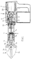
- la figure 1 illustre la position de l'élément actif agissant en tant que cisaille (position fermée) et ;
- la figure 2 est une vue similaire illustrant la position de l'élément actif en position ouverte (fonction écarteur) ;
- les figures 3 et 4 sont des vues agrandies montrant plus en détail la manière dont est réalisée la commande hydraulique permettant d'obtenir les positions respectives de l'outil représenté aux figures 1 et 2.
- Si l'on se reporte aux schémas annexés, l'outil autonome, polyvalent, permettant une utilisation aussi bien en tant que cisaille qu'en tant qu'écarteur, se présente sous la forme d'un ensemble comportant un vérin hydraulique, désigné par la référence générale (1), dont la tige (2) actionne l'outil (3) proprement dit, constitué essentiellement de deux lames ou bras (3a,3b), articulés autour d'un axe commun (4) et montés sur une chape (5) solidaire du corps du vérin, l'ouverture et la fermeture desdites lames (3a,3b) étant provoquées par l'intermédiaire d'un système à biellettes (6a,6b) commandé directement par la tige (2) du vérin (1).
- Conformément à l'invention, et ainsi que cela ressort des figures annexées, la commande de l'ouverture et de la fermeture des lames (3a,3b) est obtenue par l'intermédiaire d'un ensemble, désigné par la référence générale (2), et qui est monté directement sur le corps du vérin (1) et qui permet, comme cela sera vu dans la suite de la description, de déplacer indifféremment dans un sens ou dans l'autre le piston du vérin pour commander l'écartement et le rapprochement des lames (3a,3b). Pour ce faire, ledit ensemble est constitué essentiellement par un moteur électrique (7) alimenté par une batterie (8) intégrée dans le boitier de l'outil. On utilisera par exemple un moteur douze volts alimenté en courant continu. L'arbre de sortie de ce moteur (7) (associé ou non à un réducteur) permet de commander des moyens permettant d'assurer la compression d'un fluide sous pression disposé dans une chambre étanche (9). Un système répartiteur (10) est associé aux éléments précités pour alimenter un circuit réversible permettant de faire agir ledit fluide sous pression indifféremment sur les deux faces (11a) ou (11b) du piston (11) du vérin (1).
- L'ensemble de compression du fluide est constitué essentiellement par un excentrique (12) entraîné directement par l'arbre de sortie du moteur (7) excentrique qui commande un élément basculeur (13) qui agit sur une pompe (14) permettant d'envoyer le fluide sous pression dans un conduit axial central (15). En regard de la sortie de ce conduit d'alimentation (15), est disposé l'ensemble distributeur et répartiteur proprement dit (10). Un tel ensemble répartiteur est constitué par un boitier coulissant comportant des circuits permettant de transférer le fluide sous pression provenant au travers d'un conduit axial (15) relié à ladite pompe (14), soit au travers d'un conduit d'alimentation (16) permettant d'agir contre la face (11a) du piston (11), afin de le repousser (position représentée aux figures 1 et 3), ce qui entraîne la fermeture des organes actifs (3) soit, au travers d'un conduit (18) débouchant au regard d'un canal coaxial (17) à l'axe du piston, et qui permet d'agir alors sur la face (11b) dudit piston (11) (position représentée à la figure 4) tendant alors à écarter les deux éléments actifs (3a,3b) l'un de l'autre (figure 2).
- Par ailleurs, afin de compenser les différences de volume de fluide à l'intérieur de la chambre, une membrane souple (20) est disposée dans ladite chambre et permet donc d'éviter la formation d'une dépression lors des déplacements du fluide pour actionner l'outil. Enfin, un limiteur de pression (21) est associé au conduit axial (15) et assure une sécurité totale de fonctionnement de l'ensemble.
- Dans le premier mode d'action (figures 1 et 3), le retour du fluide qui était contenu à l'intérieur de la chambre du piston, s'effectue au travers du conduit axial (17), du conduit (18) et d'un conduit (19) de retour débouchant à l'intérieur de la chambre (9). Dans le deuxième cas (action de l'outil en position écartée (figures 2 et 4)), le retour du fluide contenu à l'intérieur de la chambre du piston s'effectue au travers du conduit (16) et du conduit de retour (19) à l'intérieur de la chambre (9). On obtient ainsi un circuit de commande parfaitement réversible et permettant d'avoir des actions d'intensité élevée et égales tant lors de l'écartement que du rapprochement des lames constituant la partie active de l'outil.
- Ainsi que cela ressort des figures annexées, de façon préférentielle, le moteur d'entraînement (7) (éventuellement associé à un réducteur), est aligné avec l'axe du vérin hydraulique commandant les lames de l'outil, la batterie d'alimentation étant, quant à elle, disposée latéralement par rapport à l'ensemble précité, permettant ainsi d'obtenir un outil compact, équilibré. Par ailleurs, si pour assurer la compression du fluide, on utilise un système à levier basculant (13) ayant deux bras de longueur égale, il pourrait être envisagé d'obtenir une démultiplication en décalant l'axe de pivotement dudit levier (13) par rapport à sa longueur.
- Un tel ensemble qui est de conception particulièrement simple, présente une grande efficacité et permet d'obtenir une action parfaitement réversible de l'outil (3) permettant son utilisation aussi bien en tant que cisaille (figures 1 et 2) qu'en tant qu'écarteur (figures 2 et 4).
- Il est particulièrement adapté pour réaliser des outils portables permettant d'intervenir sur n'importe quel site. Par ailleurs, il est évident que l'on ne sort pas du cadre de l'invention en réalisant des outils autonomes ayant une commande hydraulique similaire, l'organe actif pouvant avoir une autre structure. Il peut être ainsi envisagé de réaliser des poinçonneuses, coupe-câbles.. .
Claims (3)
Applications Claiming Priority (2)
| Application Number | Priority Date | Filing Date | Title |
|---|---|---|---|
| FR9107837 | 1991-06-20 | ||
| FR9107837A FR2677908B1 (fr) | 1991-06-20 | 1991-06-20 | Outil autonome polyvalent tel que cisaille/ecarteur a commande hydraulique. |
Publications (2)
| Publication Number | Publication Date |
|---|---|
| EP0519845A1 true EP0519845A1 (fr) | 1992-12-23 |
| EP0519845B1 EP0519845B1 (fr) | 1997-07-30 |
Family
ID=9414278
Family Applications (1)
| Application Number | Title | Priority Date | Filing Date |
|---|---|---|---|
| EP92420205A Revoked EP0519845B1 (fr) | 1991-06-20 | 1992-06-16 | Outil autonome polyvalent tel que cisaille/écarteur à commande hydraulique |
Country Status (5)
| Country | Link |
|---|---|
| US (1) | US5272811A (fr) |
| EP (1) | EP0519845B1 (fr) |
| JP (1) | JPH05177427A (fr) |
| DE (1) | DE69221221T2 (fr) |
| FR (1) | FR2677908B1 (fr) |
Cited By (6)
| Publication number | Priority date | Publication date | Assignee | Title |
|---|---|---|---|---|
| WO1996034657A1 (fr) * | 1995-05-04 | 1996-11-07 | Weber-Hydraulik Gmbh | Outil de deformation |
| EP1498204A3 (fr) * | 2003-07-17 | 2005-07-20 | Lukas Hydraulik GmbH | Outil ayant un premier ainsi qu'un deuxième circuit pour les moyens de mise en marche |
| CN105345123A (zh) * | 2015-11-10 | 2016-02-24 | 王怀章 | 一种双向精密液压棒料剪断机及其剪切方法 |
| WO2016119819A1 (fr) * | 2015-01-26 | 2016-08-04 | Lukas Hydraulik Gmbh | Organe de travail hydraulique |
| CN106310550A (zh) * | 2016-09-16 | 2017-01-11 | 宁夏吴忠市好运电焊机有限公司 | 简易破窗器 |
| FR3056128A1 (fr) * | 2016-09-21 | 2018-03-23 | Hydram | Ensemble autonome polyvalent a commande hydraulique |
Families Citing this family (60)
| Publication number | Priority date | Publication date | Assignee | Title |
|---|---|---|---|---|
| US5787754A (en) * | 1993-02-24 | 1998-08-04 | Carrion; Jose | Tool for compression of motor/generator windings |
| USD356478S (en) | 1994-04-08 | 1995-03-21 | Burndy Corporation | Connector crimping tool |
| US5553478A (en) * | 1994-04-08 | 1996-09-10 | Burndy Corporation | Hand-held compression tool |
| DE4414967C2 (de) * | 1994-04-28 | 1997-07-17 | Weidmueller Interface | Servozange |
| DE9412147U1 (de) * | 1994-07-27 | 1994-09-22 | Hugo Junkers Werke GmbH, 82216 Maisach | Mobiles Hydrauliksystem |
| US5727417A (en) * | 1995-09-22 | 1998-03-17 | Greenlee Textron Inc. | Portable battery powered crimper |
| USD386661S (en) * | 1995-10-13 | 1997-11-25 | Japan Storage Battery Co., Ltd. | Portable electro-hydraulic cable cutter |
| USD387961S (en) * | 1995-10-13 | 1997-12-23 | Japan Storage Battery Co., Ltd. | Portable electro-hydraulic cutter |
| US5953822A (en) * | 1996-12-24 | 1999-09-21 | Rescue Technology, Inc. | Rescue tool |
| US6092290A (en) * | 1996-12-24 | 2000-07-25 | Rescue Technology, Inc. | Rescue tool |
| US5875554A (en) * | 1996-12-24 | 1999-03-02 | Rescue Technology, Inc. | Rescue tool |
| US5918370A (en) * | 1997-10-09 | 1999-07-06 | Jarvis Products Corporation | Hand held power assisted shears |
| DE19806051A1 (de) * | 1998-02-13 | 1999-08-26 | Honsel M H Beteiligungs Gmbh | Nietsetzgerät |
| USD416567S (en) | 1998-07-29 | 1999-11-16 | Rescue Technology, Inc. | Cutting blade |
| SE9802717L (sv) * | 1998-08-13 | 2000-02-14 | Nike Hydraulics Ab | Fluidumpåverkat räddningsverktyg |
| US6138346A (en) * | 1998-12-21 | 2000-10-31 | Connectool Inc. | Portable hand-held battery-powered crimping tool |
| DE19903020A1 (de) | 1999-01-26 | 2000-08-03 | Honsel M H Beteiligungs Gmbh | Nietsetzgerät |
| EP1055488B1 (fr) * | 1999-05-28 | 2007-08-08 | REMS-WERK Christian Föll und Söhne GmbH & Co | Dispositif pour l'application d'une force de pressage |
| US6178643B1 (en) | 1999-07-08 | 2001-01-30 | Electroline Corporation | Hand-held ratchet action tool |
| US6349474B1 (en) | 2000-05-31 | 2002-02-26 | The United States Of America As Represented By The Secretary Of The Navy | Cable cutter |
| US6453719B1 (en) | 2000-07-28 | 2002-09-24 | Fci Usa, Inc. | Hydraulic tool with forward surrounding reservoir |
| US6662620B1 (en) | 2000-09-12 | 2003-12-16 | Black & Decker Inc. | Steel stud crimper |
| JP4883599B2 (ja) * | 2001-05-15 | 2012-02-22 | 株式会社泉精器製作所 | 切断工具 |
| DE10124267B4 (de) * | 2001-05-18 | 2014-04-10 | Gustav Klauke Gmbh | Hydraulisches Pressgerät |
| US6880378B1 (en) * | 2001-07-18 | 2005-04-19 | Vindee Industries, Inc. | Chain cutter |
| US6446482B1 (en) | 2001-09-17 | 2002-09-10 | Fci Americas Technology, Inc. | Battery operated hydraulic compression tool with rapid ram advance |
| NL1020225C1 (nl) * | 2002-03-21 | 2003-09-23 | Holmatro Ind Equip | Door een batterij gevoed hydraulisch reddingsgereedschap. |
| RU2238178C2 (ru) * | 2002-06-11 | 2004-10-20 | Панюхно Геннадий Анатольевич | Переносной гидравлический инструмент |
| JP3977155B2 (ja) * | 2002-06-14 | 2007-09-19 | 株式会社オグラ | 油圧作動装置 |
| US6971179B2 (en) | 2002-09-27 | 2005-12-06 | Electroline Corporation | Cutting tool |
| US7346987B2 (en) * | 2002-09-27 | 2008-03-25 | Electroline Corporation | Cutting tool with work piece feed mechanism |
| USD516399S1 (en) * | 2002-11-26 | 2006-03-07 | Kabushiki Kaisha Ogura | Portable hydraulic spreader device |
| USD492949S1 (en) | 2003-01-22 | 2004-07-13 | Kabushiki Kaisha Ogura | Portable hydraulic spreader device |
| ATE368551T1 (de) * | 2003-12-04 | 2007-08-15 | Arx Ag | Elektrisch betriebenes presswerkzeugger t |
| USD521341S1 (en) * | 2004-04-06 | 2006-05-23 | Kabushiki Kaisha Ogura | Lock opening device |
| USD523314S1 (en) * | 2004-04-06 | 2006-06-20 | Kabushiki Kaisha Ogura | Lock opening device |
| EP1658907A1 (fr) * | 2004-11-17 | 2006-05-24 | Dino Sodini | Outil pour la correction des carrosseries abîmées |
| NL1028334C2 (nl) * | 2005-02-18 | 2006-08-21 | Holmatro Ind Equip | Scharnierboutconstructie met borging. |
| DE102005024039A1 (de) * | 2005-05-25 | 2006-12-07 | Lukas Hydraulik Gmbh | Werkzeugarm aus Verbundmaterial, Verfahren zu seiner Herstellung sowie Werkzeugeinheit |
| US7331109B2 (en) * | 2006-05-12 | 2008-02-19 | Shu-Woan Tu | Electric cutting device |
| USD591128S1 (en) * | 2008-02-15 | 2009-04-28 | First Forever Co., Ltd. | Crimping cutting power tool |
| JP5332662B2 (ja) * | 2009-01-30 | 2013-11-06 | マックス株式会社 | 電動はさみ |
| US10226826B2 (en) | 2013-10-22 | 2019-03-12 | Milwaukee Electric Tool Corporation | Hydraulic power tool |
| CN205977914U (zh) | 2015-05-06 | 2017-02-22 | 米沃奇电动工具公司 | 液压动力工具 |
| JP1544593S (fr) * | 2015-05-18 | 2016-02-29 | ||
| NL2014868B1 (nl) * | 2015-05-27 | 2017-01-02 | Jpm Beheer B V | Reddingsgereedschap. |
| CA2922295A1 (fr) | 2016-03-02 | 2017-09-02 | Off The X Inc. | Dispositif d'enfoncement de porte |
| EP3307489B1 (fr) * | 2016-05-06 | 2019-07-03 | Lukas Hydraulik GmbH | Procédé permettant de faire fonctionner un outil de travail ou un appareil de sauvetage et outil de travail ou appareil de sauvetage |
| CN106625422B (zh) * | 2017-02-13 | 2019-08-20 | 杭州众铎消防科技有限公司 | 电动剪扩器 |
| AT520046B1 (de) | 2017-06-12 | 2022-10-15 | Weber Hydraulik Gmbh | Hydraulikaggregat für hydraulische Rettungswerkzeuge sowie damit ausgestattetes Rettungswerkzeug |
| EP3650176B1 (fr) * | 2018-11-07 | 2025-12-24 | Emerson Professional Tools AG | Machine à presser |
| EP3840842B1 (fr) * | 2018-11-26 | 2022-10-26 | Lukas Hydraulik GmbH | Appareil de travail portatif destiné à un usage portable |
| JP7235619B2 (ja) * | 2019-07-30 | 2023-03-08 | 株式会社オグラ | 油圧作動装置 |
| US11638842B2 (en) * | 2020-10-26 | 2023-05-02 | Snap-On Incorporated | Portable electric rescue tool |
| US11406060B1 (en) | 2021-02-04 | 2022-08-09 | Tortuga Agricultural Technologies, Inc. | End effector for harvesting |
| WO2022271632A1 (fr) | 2021-06-21 | 2022-12-29 | Milwaukee Electric Tool Corporation | Systèmes et procédés d'évaluation d'applications de sertissage |
| US12627107B2 (en) | 2021-08-11 | 2026-05-12 | Milwaukee Electric Tool Corporation | System and methods for determining crimp applications and reporting power tool usage |
| CN113977714B (zh) * | 2021-11-11 | 2023-05-30 | 南京尚科得科技发展有限公司 | 一种木材加工用省力木工刨 |
| WO2024223055A1 (fr) | 2023-04-28 | 2024-10-31 | Lukas Hydraulik Gmbh | Système de pompe hydraulique |
| AU2024338704B2 (en) * | 2023-09-07 | 2026-04-16 | Kempe Services Pilbara Pty Ltd | Hydraulic crowbar assembly |
Citations (5)
| Publication number | Priority date | Publication date | Assignee | Title |
|---|---|---|---|---|
| EP0235403A1 (fr) * | 1985-10-18 | 1987-09-09 | Gianni Citton | Appareil moteur portable à têtes échangeables |
| EP0274710A1 (fr) * | 1986-12-18 | 1988-07-20 | Raffaele Agostini | Pince motorisée portable pour le serrage de cavaliers ou similaires |
| FR2623738A1 (fr) * | 1987-12-01 | 1989-06-02 | Amga Sa | Dispositif de coupe, tel que cisaille, a commande hydraulique |
| FR2644383A1 (fr) * | 1989-03-14 | 1990-09-21 | Beaudon Gerard | Outillage pour l'execution d'operations diverses, notamment sertissage |
| EP0389716A1 (fr) * | 1989-03-31 | 1990-10-03 | Japan Storage Battery Company Limited | Mécanisme à came et outil hydraulique motorisé |
Family Cites Families (8)
| Publication number | Priority date | Publication date | Assignee | Title |
|---|---|---|---|---|
| US2343595A (en) * | 1940-05-23 | 1944-03-07 | Cleveland Pneumatic Tool Co | Portable tool |
| US3765087A (en) * | 1969-08-05 | 1973-10-16 | J Pawloski | Powered cutting tool and cutting head therefor |
| US3693254A (en) * | 1970-08-26 | 1972-09-26 | Albert R Salonen | Motorized shearing implement |
| US4181003A (en) * | 1978-09-12 | 1980-01-01 | Kononov Ivan V | Hydraulic screw press drive |
| US4458418A (en) * | 1981-10-06 | 1984-07-10 | The United States Of America As Represented By The Administrator Of The National Aeronautics And Space Administration | Tubing and cable cutting tool |
| FR2536246A1 (fr) * | 1982-11-22 | 1984-05-25 | Pellenc & Motte | Outils hydrauliques portatifs, par exemple secateurs hydrauliques, et procede de rappel du piston de leur verin |
| US4998351A (en) * | 1989-06-14 | 1991-03-12 | Hartmeister Ruben J | Power driven hand tool assembly |
| FR2649922B1 (fr) * | 1989-07-21 | 1994-01-21 | Hydr Am | Ecarteur perfectionne a commande hydraulique |
-
1991
- 1991-06-20 FR FR9107837A patent/FR2677908B1/fr not_active Expired - Fee Related
-
1992
- 1992-06-16 DE DE69221221T patent/DE69221221T2/de not_active Revoked
- 1992-06-16 EP EP92420205A patent/EP0519845B1/fr not_active Revoked
- 1992-06-17 JP JP4158068A patent/JPH05177427A/ja active Pending
- 1992-06-17 US US07/900,182 patent/US5272811A/en not_active Expired - Fee Related
Patent Citations (5)
| Publication number | Priority date | Publication date | Assignee | Title |
|---|---|---|---|---|
| EP0235403A1 (fr) * | 1985-10-18 | 1987-09-09 | Gianni Citton | Appareil moteur portable à têtes échangeables |
| EP0274710A1 (fr) * | 1986-12-18 | 1988-07-20 | Raffaele Agostini | Pince motorisée portable pour le serrage de cavaliers ou similaires |
| FR2623738A1 (fr) * | 1987-12-01 | 1989-06-02 | Amga Sa | Dispositif de coupe, tel que cisaille, a commande hydraulique |
| FR2644383A1 (fr) * | 1989-03-14 | 1990-09-21 | Beaudon Gerard | Outillage pour l'execution d'operations diverses, notamment sertissage |
| EP0389716A1 (fr) * | 1989-03-31 | 1990-10-03 | Japan Storage Battery Company Limited | Mécanisme à came et outil hydraulique motorisé |
Cited By (14)
| Publication number | Priority date | Publication date | Assignee | Title |
|---|---|---|---|---|
| WO1996034657A1 (fr) * | 1995-05-04 | 1996-11-07 | Weber-Hydraulik Gmbh | Outil de deformation |
| EP1498204A3 (fr) * | 2003-07-17 | 2005-07-20 | Lukas Hydraulik GmbH | Outil ayant un premier ainsi qu'un deuxième circuit pour les moyens de mise en marche |
| US10293192B2 (en) | 2015-01-26 | 2019-05-21 | Lukas Hydraulik Gmbh | Hydraulic implement |
| WO2016119819A1 (fr) * | 2015-01-26 | 2016-08-04 | Lukas Hydraulik Gmbh | Organe de travail hydraulique |
| EP3197564B1 (fr) | 2015-01-26 | 2019-01-09 | Lukas Hydraulik GmbH | Organe de travail hydraulique |
| EP3434331A3 (fr) * | 2015-01-26 | 2019-03-20 | Lukas Hydraulik GmbH | Organe de travail hydraulique |
| EP3434331B1 (fr) | 2015-01-26 | 2020-02-19 | Lukas Hydraulik GmbH | Organe de travail hydraulique |
| US10589135B2 (en) | 2015-01-26 | 2020-03-17 | Lukas Hydraulik Gmbh | Hydraulic implement |
| CN105345123A (zh) * | 2015-11-10 | 2016-02-24 | 王怀章 | 一种双向精密液压棒料剪断机及其剪切方法 |
| CN105345123B (zh) * | 2015-11-10 | 2019-07-30 | 王怀章 | 一种双向精密液压棒料剪断机及其剪切方法 |
| CN106310550A (zh) * | 2016-09-16 | 2017-01-11 | 宁夏吴忠市好运电焊机有限公司 | 简易破窗器 |
| CN106310550B (zh) * | 2016-09-16 | 2022-05-10 | 宁夏吴忠市好运电焊机有限公司 | 简易破窗器 |
| FR3056128A1 (fr) * | 2016-09-21 | 2018-03-23 | Hydram | Ensemble autonome polyvalent a commande hydraulique |
| EP3299103A1 (fr) | 2016-09-21 | 2018-03-28 | Hydr'am | Ensemble autonome polyvalent à commande hydraulique |
Also Published As
| Publication number | Publication date |
|---|---|
| EP0519845B1 (fr) | 1997-07-30 |
| JPH05177427A (ja) | 1993-07-20 |
| US5272811A (en) | 1993-12-28 |
| FR2677908A1 (fr) | 1992-12-24 |
| FR2677908B1 (fr) | 1995-04-07 |
| DE69221221D1 (de) | 1997-09-04 |
| DE69221221T2 (de) | 1997-11-27 |
Similar Documents
| Publication | Publication Date | Title |
|---|---|---|
| EP0519845B1 (fr) | Outil autonome polyvalent tel que cisaille/écarteur à commande hydraulique | |
| CA2073518C (fr) | Vibrateur a moment variable utilisable notamment a l'enfoncement d'objets dans le sol | |
| EP0291431B1 (fr) | Outil électrique portable à asservissement en position | |
| EP0662894B1 (fr) | Dispositif de freinage assiste a reaction hydraulique ralentie | |
| WO1994009285A1 (fr) | Moteur de frein a encombrement reduit | |
| FR2642813A1 (fr) | Moyen d'entrainement a moteur electrique pour un organe de manoeuvre | |
| EP4103359B1 (fr) | Outil et procédé de sertissage d'un élément sur un support | |
| FR2599447A1 (fr) | Cylindre de commande d'un embrayage actionne par fluide sous pression | |
| EP1191259A1 (fr) | Dispositif de lubrification d'une boíte de transmission de puissance présentant une orientation variable, en particulier pour un aéronef convertible à rotors basculants | |
| EP0128096B1 (fr) | Actionneur à accumulateur d'énergie pneumatique notamment pour robinet | |
| FR2589968A1 (fr) | Dispositif de graissage d'une commande d'arbre d'un vehicule automobile | |
| WO1994007721A1 (fr) | Dispositif de freinage assiste a reaction hydraulique et saut reglable | |
| FR2595644A1 (fr) | Dispositif modulateur de pression | |
| EP1123233B1 (fr) | Maitre-cylindre a reaction hydraulique et a effort d'entree accru | |
| EP3078101A1 (fr) | Actionneur electrique a moyens manuels d'entrainement | |
| EP3139726B1 (fr) | Machine agricole comportant un dispositif perfectionne de commande d'un protecteur | |
| EP3140238B1 (fr) | Treuil modulaire embarque | |
| FR2645804A1 (fr) | Actionneur pour embrayage pilote, notamment pour vehicule automobile | |
| CA2654496C (fr) | Appareil rotopercutant hydraulique du type perforatrice | |
| EP0498682A1 (fr) | Dispositif de commande de soupape à fonction de mise à l'arrêt pour moteur à combustion interne | |
| EP0687481A1 (fr) | Procédé et dispositif de commande d'alimentation de vérin de manoeuvre d'outils hydrauliques | |
| FR2563279A1 (fr) | Connecteur reglable du papillon de commande des gaz pour une unite de reglage de la vitesse d'un vehicule | |
| EP0331854A1 (fr) | Actionneur utilisant un fluide sous pression pour l'entraînement en rotation d'un arbre rotatif | |
| FR2711739A1 (fr) | Pompe de lubrification pour moteur à combustion interne. | |
| FR2696143A1 (fr) | Dispositif de freinage assisté à réaction hydraulique ralentie. |
Legal Events
| Date | Code | Title | Description |
|---|---|---|---|
| PUAI | Public reference made under article 153(3) epc to a published international application that has entered the european phase |
Free format text: ORIGINAL CODE: 0009012 |
|
| AK | Designated contracting states |
Kind code of ref document: A1 Designated state(s): DE ES GB IT NL |
|
| 17P | Request for examination filed |
Effective date: 19930228 |
|
| 17Q | First examination report despatched |
Effective date: 19940627 |
|
| GRAG | Despatch of communication of intention to grant |
Free format text: ORIGINAL CODE: EPIDOS AGRA |
|
| GRAH | Despatch of communication of intention to grant a patent |
Free format text: ORIGINAL CODE: EPIDOS IGRA |
|
| RAP1 | Party data changed (applicant data changed or rights of an application transferred) |
Owner name: HYDR'AM |
|
| GRAH | Despatch of communication of intention to grant a patent |
Free format text: ORIGINAL CODE: EPIDOS IGRA |
|
| GRAA | (expected) grant |
Free format text: ORIGINAL CODE: 0009210 |
|
| AK | Designated contracting states |
Kind code of ref document: B1 Designated state(s): DE ES GB IT NL |
|
| PG25 | Lapsed in a contracting state [announced via postgrant information from national office to epo] |
Ref country code: IT Free format text: LAPSE BECAUSE OF FAILURE TO SUBMIT A TRANSLATION OF THE DESCRIPTION OR TO PAY THE FEE WITHIN THE PRESCRIBED TIME-LIMIT;WARNING: LAPSES OF ITALIAN PATENTS WITH EFFECTIVE DATE BEFORE 2007 MAY HAVE OCCURRED AT ANY TIME BEFORE 2007. THE CORRECT EFFECTIVE DATE MAY BE DIFFERENT FROM THE ONE RECORDED. Effective date: 19970730 Ref country code: GB Free format text: LAPSE BECAUSE OF FAILURE TO SUBMIT A TRANSLATION OF THE DESCRIPTION OR TO PAY THE FEE WITHIN THE PRESCRIBED TIME-LIMIT Effective date: 19970730 |
|
| REF | Corresponds to: |
Ref document number: 69221221 Country of ref document: DE Date of ref document: 19970904 |
|
| PG25 | Lapsed in a contracting state [announced via postgrant information from national office to epo] |
Ref country code: ES Free format text: LAPSE BECAUSE OF FAILURE TO SUBMIT A TRANSLATION OF THE DESCRIPTION OR TO PAY THE FEE WITHIN THE PRESCRIBED TIME-LIMIT Effective date: 19971031 |
|
| GBV | Gb: ep patent (uk) treated as always having been void in accordance with gb section 77(7)/1977 [no translation filed] |
Effective date: 19970730 |
|
| PLBQ | Unpublished change to opponent data |
Free format text: ORIGINAL CODE: EPIDOS OPPO |
|
| PLAV | Examination of admissibility of opposition |
Free format text: ORIGINAL CODE: EPIDOS OPEX |
|
| PLBI | Opposition filed |
Free format text: ORIGINAL CODE: 0009260 |
|
| PLBF | Reply of patent proprietor to notice(s) of opposition |
Free format text: ORIGINAL CODE: EPIDOS OBSO |
|
| 26 | Opposition filed |
Opponent name: LUKAS HYDRAULIK GMBH & CO. KG Effective date: 19980429 |
|
| NLR1 | Nl: opposition has been filed with the epo |
Opponent name: LUKAS HYDRAULIK GMBH & CO. KG |
|
| PLBF | Reply of patent proprietor to notice(s) of opposition |
Free format text: ORIGINAL CODE: EPIDOS OBSO |
|
| PLBF | Reply of patent proprietor to notice(s) of opposition |
Free format text: ORIGINAL CODE: EPIDOS OBSO |
|
| PGFP | Annual fee paid to national office [announced via postgrant information from national office to epo] |
Ref country code: NL Payment date: 20010517 Year of fee payment: 10 |
|
| PGFP | Annual fee paid to national office [announced via postgrant information from national office to epo] |
Ref country code: DE Payment date: 20010613 Year of fee payment: 10 |
|
| RDAH | Patent revoked |
Free format text: ORIGINAL CODE: EPIDOS REVO |
|
| RDAG | Patent revoked |
Free format text: ORIGINAL CODE: 0009271 |
|
| 27W | Patent revoked |
Effective date: 20020127 |
|
| NLR2 | Nl: decision of opposition |