EP0520844A1 - Elektroventil für Antiblockiervorrichtung - Google Patents
Elektroventil für Antiblockiervorrichtung Download PDFInfo
- Publication number
- EP0520844A1 EP0520844A1 EP92401427A EP92401427A EP0520844A1 EP 0520844 A1 EP0520844 A1 EP 0520844A1 EP 92401427 A EP92401427 A EP 92401427A EP 92401427 A EP92401427 A EP 92401427A EP 0520844 A1 EP0520844 A1 EP 0520844A1
- Authority
- EP
- European Patent Office
- Prior art keywords
- pressure
- solenoid valve
- constant
- drawer
- piston means
- Prior art date
- Legal status (The legal status is an assumption and is not a legal conclusion. Google has not performed a legal analysis and makes no representation as to the accuracy of the status listed.)
- Granted
Links
Images

Classifications
-
- B—PERFORMING OPERATIONS; TRANSPORTING
- B60—VEHICLES IN GENERAL
- B60T—VEHICLE BRAKE CONTROL SYSTEMS OR PARTS THEREOF; BRAKE CONTROL SYSTEMS OR PARTS THEREOF, IN GENERAL; ARRANGEMENT OF BRAKING ELEMENTS ON VEHICLES IN GENERAL; PORTABLE DEVICES FOR PREVENTING UNWANTED MOVEMENT OF VEHICLES; VEHICLE MODIFICATIONS TO FACILITATE COOLING OF BRAKES
- B60T8/00—Arrangements for adjusting wheel-braking force to meet varying vehicular or ground-surface conditions, e.g. limiting or varying distribution of braking force
- B60T8/32—Arrangements for adjusting wheel-braking force to meet varying vehicular or ground-surface conditions, e.g. limiting or varying distribution of braking force responsive to a speed condition, e.g. acceleration or deceleration
- B60T8/34—Arrangements for adjusting wheel-braking force to meet varying vehicular or ground-surface conditions, e.g. limiting or varying distribution of braking force responsive to a speed condition, e.g. acceleration or deceleration having a fluid pressure regulator responsive to a speed condition
- B60T8/36—Arrangements for adjusting wheel-braking force to meet varying vehicular or ground-surface conditions, e.g. limiting or varying distribution of braking force responsive to a speed condition, e.g. acceleration or deceleration having a fluid pressure regulator responsive to a speed condition including a pilot valve responding to an electromagnetic force
- B60T8/3615—Electromagnetic valves specially adapted for anti-lock brake and traction control systems
-
- B—PERFORMING OPERATIONS; TRANSPORTING
- B60—VEHICLES IN GENERAL
- B60T—VEHICLE BRAKE CONTROL SYSTEMS OR PARTS THEREOF; BRAKE CONTROL SYSTEMS OR PARTS THEREOF, IN GENERAL; ARRANGEMENT OF BRAKING ELEMENTS ON VEHICLES IN GENERAL; PORTABLE DEVICES FOR PREVENTING UNWANTED MOVEMENT OF VEHICLES; VEHICLE MODIFICATIONS TO FACILITATE COOLING OF BRAKES
- B60T15/00—Construction arrangement, or operation of valves incorporated in power brake systems and not covered by groups B60T11/00 or B60T13/00
- B60T15/02—Application and release valves
- B60T15/025—Electrically controlled valves
- B60T15/028—Electrically controlled valves in hydraulic systems
-
- Y—GENERAL TAGGING OF NEW TECHNOLOGICAL DEVELOPMENTS; GENERAL TAGGING OF CROSS-SECTIONAL TECHNOLOGIES SPANNING OVER SEVERAL SECTIONS OF THE IPC; TECHNICAL SUBJECTS COVERED BY FORMER USPC CROSS-REFERENCE ART COLLECTIONS [XRACs] AND DIGESTS
- Y10—TECHNICAL SUBJECTS COVERED BY FORMER USPC
- Y10T—TECHNICAL SUBJECTS COVERED BY FORMER US CLASSIFICATION
- Y10T137/00—Fluid handling
- Y10T137/8593—Systems
- Y10T137/87169—Supply and exhaust
- Y10T137/87217—Motor
Definitions
- the present invention relates to a solenoid valve, more particularly intended to be inserted in a hydraulic braking circuit for a motor vehicle, between a master cylinder and the brake motors in an anti-lock braking system.
- Hydraulic braking circuits with anti-lock braking device are known and typically comprise between the source of pressurized brake fluid such as an electric pump or a so-called “full power" master cylinder and the brake motors, controlled solenoid valves by a computer, allowing the pressure in the brake motors to be lowered when the computer detects a wheel lock, and a temperate rise in pressure in the brake motors when the computer detects too high a speed of rotation of the wheels.
- the solenoid valves used in these anti-lock braking devices are generally two-position and all-or-nothing solenoid valves and generate great energy consumption on the part of the electropump due to the succession of phases. intake / detent during operation of the anti-lock device. It has also been proposed to use proportional solenoid valves, but when it is desired to minimize the hydraulic leaks in order to reduce the energy consumption of the electric pump, a phenomenon of hysteresis appears in the curve representing the hydraulic pressure in the motors. brake as a function of the actuation force of the solenoid valve, and therefore of the electric current flowing therein, this hysteresis disturbing the management of the pressure in the brake motor by the computer associated with the anti-lock device.
- the present invention therefore aims to provide a solenoid valve for an anti-lock device for the wheels whose energy consumption is as low as possible, and which is simple and reliable, and which allows precise control of the pressure in the brake motors.
- an electrovalve in particular intended to be inserted in a hydraulic braking circuit between at least one source of pressurized brake fluid and at least one pressure receiver in an anti-lock wheel system, comprising in a body a piston means movable between a rest position where it allows communication between the source of pressurized fluid and the pressure receptor and a working position where it allows communication between the pressure receptor and a low-pressure fluid reservoir, characterized in that the piston means is constantly urged towards its rest position by a constant force.
- this constant force is obtained by the application of a constant pressure on a constant surface, in particular of the piston means.
- the constant surface is formed on a drawer constituting the piston means, on a section of a span of this drawer or on the difference of the sections of two spans of the drawer.
- the solenoid valve of the invention may include a pressure limiter capable of supplying the constant pressure from the source pressure, this limiter itself comprising a second slide movable under the effect of the source pressure at against a force exerted by a return spring, this spring being calibrated to a value such that this second drawer, thanks to its displacement, escapes the effect of the source pressure as soon as it exceeds said pressure constant.
- the constant pressure is fixed at a relatively low value, for example between 5 and 10 bars.
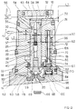
- the solenoid valve shown in Figure 1 consists of a body 10 of generally cylindrical shape, one of the ends 12 of which is provided with a bore 14 for fixing, for example by screwing, the base 16 of an electromagnet 18 (not shown) actuating, under the control of a computer, (not shown) a pusher 20.
- the drawer 24 mainly comprises two bearing surfaces 26 and 28 on either side of a groove defining an annular volume 30.
- a blind bore 32 is formed axially in the drawer 24 and opens into a radial bore 34 formed in the drawer 24 at the level of the bearing surface 28.
- Another radial bore 36 is formed in the slide 24 at the level of the annular groove 30.
- the drawer 24 is returned to its rest position by a return spring 38, taking support on the one hand on a shoulder 40 formed in the body 10 between the bores 22 and 14, and on the other hand on a cup 42 taking it -same support on a stop washer 44 integral with the drawer 24.
- the rest position of the drawer 24 is defined by a pin 46 inserted in the body 10 and cooperating with an oblong slot 48 formed radially in the drawer 24.
- the annular groove 30 of the drawer 24 allows communication between a passage 50 formed in the body 10 and connected to a source of pressurized fluid 52 such as a master cylinder and a passage 54 also formed in the body 10 and connected to a pressure receiver 56 such as a brake motor.
- a closure element 57 in the blind bore 32 confines the pressurized fluid in this bore, the bore 34 being closed by the tight cooperation of the bearing 28 with the wall of the bore 22 of the body 10.
- the solenoid valve therefore allows conventional operation of the braking circuit of the vehicle thus equipped, for braking not requiring the intervention of the anti-lock device of the wheels.
- the computer When the computer detects the impending locking of a wheel, it controls the excitation of the electromagnet 18.
- the pusher 20 then comes into abutment against a ball 58 secured to a guide 60 sliding in the bore 32 of the drawer 24, and biased towards the pusher 20 by a return spring 62 disposed between a shoulder of the guide 60 and the stop washer 44.
- the ball 58 constitutes the movable element of a ball valve which cooperates with a valve seat 59 formed on the base 16 of the electromagnet 18 coaxially with the pusher 20.
- the valve 58-59 is thus closed at rest, that is to say outside of the anti-lock phases, to seal the electromagnet internal circuits of the solenoid valve which communicate with the braking circuit.
- the pusher 20 comes first to urge the ball 58 and the guide 60 against the spring 62 until the guide 60 abuts against the slide 24, then the latter is also biased (upwards in FIG. 1) against the spring 38.
- the bearing surface 26 of the drawer 24 firstly closes the passage 50, thus preventing the supply of pressurized fluid to the receiver 56, then the bearing 28 of the drawer 24 is displaced enough so that the bore 34 is uncovered and opens into a chamber 64 formed at the end of the body 10 opposite that which receives the electromagnet 18, and closed by a plug 65.
- the chamber 64 is connected by a bore 67 made in the body 10 to the annular space 68 around the ball 58 and the guide 60, and to the annular space 69 around the pusher 20 when it lifts the ball 58 from its seat 59 when the electromagnet is energized.
- the annular space 69 is itself in communication with a reservoir of fluid under low pressure 66.
- the pressure receiver 56 therefore communicates, when the electromagnet 18 is energized, with the low-pressure reservoir 66, via the passage 54, the annular groove 30, the radial bore 36, the axial bore 32, the radial bore 34, the chamber 64, the bore 67, and the annular spaces 68 and 69, the axial bore 32 being moreover closed by the element 57 as seen above.
- the pressure in the pressure receiver 56 can then drop, until the computer detects too high a rotation speed in the wheel associated with the receiver 56.
- the computer controls the de-excitation of the electromagnet 18, which allows the drawer 24 to return to its rest position under the effect of the return spring 38.
- the pressure receiver 56 is then isolated from the low pressure reservoir 66, and connected to the source of pressurized liquid 52. Such cycles pressure drop and rise are thus repeated until the vehicle stops or the pressure supplied by the pressure source 52 decreases, thereby eliminating the risk of wheel locking.
- the solenoid valve operates like that of Figure 1 for braking which does not require the intervention of the anti-lock braking device: the pressure transmitter 52 is connected to the pressure receiver pressure 56 through passage 50, annular groove 30 and passage 54.
- the bore 70 receives a slide 72 having two bearing surfaces 74 and 76, on either side of a groove defining an annular volume 78.
- the slide 72 is itself formed with a blind axial bore 80, opening into a bore radial 82 formed at the bearing surface 76.
- the drawer 72 is returned to its rest position by a return spring 84 bearing on the one hand on a shoulder 110 of the drawer 72 and on the other hand on the body 10 or on a cup 86 secured to the body 10, or for example interposed between the latter and the base 16 of the electromagnet 18.
- the drawer 24 has a third bearing 88 cooperating in leaktight manner with a bore 90 of the body 10, coaxial with the bore 22.
- the bearings 26 and 88 define between them and with the bores 22 and 90 an annular volume 92.
- This annular volume 92 is in constant communication, whatever the positions of the drawers 24 and 72, through a passage 94 in the body 10, with the annular volume 78 defined around the drawer 72, which is itself in communication by a passage 96 with the passage 50 for connection with the source of pressurized fluid 52.
- the bearing 76 of the drawer 72 is able to cooperate with the bore 70 to close the bore 82 in the rest position of the drawer 72, or on the contrary to unblock this bore in a chamber 98, where for example find the return spring 84, when the drawer 72 is in its working position.
- This chamber 98 is in communication by a passage 100 with the annular space 68 around the ball 58, and the annular space 69 around the pusher 20 of the electromagnet 18 if the latter is energized, itself in communication with the low pressure tank 66.
- the pusher 20 moves the slide 24 (via the ball 58 and the guide 60) to its active position.
- the annular space 102 communicates with the annular space 104, and therefore with the low-pressure reservoir 66.
- the pressure emitted by the pressure source 52 is no longer transmitted to the receiver 56 since the slide 24 is in its active position, on the other hand it is transmitted, by the passage 96, to the annular volume 78, and by the passage 94, to the annular volume 92.
- the pressure of the source 52 is exerted on the section of the bearing surface 76, a passage 106 having been made in the drawer 74 to make this volume 78 communicate with the interior of the bore 80.
- the section of the bearing surface 76 being subjected on the other side to the pressure of the low-pressure reservoir which prevails in the annular space 68, the slide 74 will move when the pressure P of the source 52 has reached a value equal to that which is necessary to overcome the force of the return spring 84. In this movement, the bearing 74 of the drawer 72 will close the passage 96, thus preventing any subsequent increase in the pressure in the annular space 78.
- this annular space 78 is at this pressure P. If the pressure in the annular volume 92 decreases, the return spring moves the slide 72 to open the passage 96, thereby raising thepressure in the annular space 78 up to the value P. If the pressure in the annular volume 92 increases, it acts on the section of the bearing surface 76 to open the passage 82 towards the reservoir, thereby decreasing the pressure in the annular space 78 up to the value P.
- the annular volume 92 is subjected to a constant pressure P, determined solely by the tare weight of the spring 84. It will therefore be possible to freely choose this spring 84 so that this pressure P has any predetermined value.
- a low P value for example between 5 and 10 bar, while the pressure emitted by the pressure source 52 can reach and even exceed 100 bar.
- the slide 24 is therefore subjected to a force F1 produced by the constant pressure P exerted on the surface S1 of the bearing surface 88, reduced by the surface S2 of the bearing surface 26.
- F1 P x (S1 - S2)
- the pressure transmitter 52 for example an electric pump, may also be of reduced size and reduced electrical consumption.
- the electrical and electronic stages for controlling the electromagnet and the electropump can therefore be greatly simplified and dissipate less energy. This therefore results in a significant reduction in the cost of the complete anti-lock device for the wheels, combined with greater reliability and simplicity of manufacture and operation.
- the solenoid valve of the invention is capable of receiving numerous variants which will appear to a person skilled in the art.
- the constant return force of the main drawer can be created in a chamber external to the body of the solenoid valve and transmitted to the drawer by a needle or a pusher passing tightly through this body.
- the tightness of such a crossing is not critical if it is made in the plug closing the chamber in communication with the reservoir under low pressure.
Landscapes
- Engineering & Computer Science (AREA)
- Physics & Mathematics (AREA)
- Electromagnetism (AREA)
- Transportation (AREA)
- Mechanical Engineering (AREA)
- Fluid Mechanics (AREA)
- Regulating Braking Force (AREA)
- Magnetically Actuated Valves (AREA)
- Valves And Accessory Devices For Braking Systems (AREA)
Applications Claiming Priority (2)
| Application Number | Priority Date | Filing Date | Title |
|---|---|---|---|
| FR9107940 | 1991-06-27 | ||
| FR9107940A FR2678228A1 (fr) | 1991-06-27 | 1991-06-27 | Electrovalve pour systeme d'antiblocage de roues. |
Publications (2)
| Publication Number | Publication Date |
|---|---|
| EP0520844A1 true EP0520844A1 (de) | 1992-12-30 |
| EP0520844B1 EP0520844B1 (de) | 1995-03-08 |
Family
ID=9414361
Family Applications (1)
| Application Number | Title | Priority Date | Filing Date |
|---|---|---|---|
| EP19920401427 Expired - Lifetime EP0520844B1 (de) | 1991-06-27 | 1992-05-26 | Elektroventil für Antiblockiervorrichtung |
Country Status (6)
| Country | Link |
|---|---|
| US (1) | US5333947A (de) |
| EP (1) | EP0520844B1 (de) |
| JP (1) | JPH05185927A (de) |
| DE (1) | DE69201602T2 (de) |
| ES (1) | ES2070599T3 (de) |
| FR (1) | FR2678228A1 (de) |
Families Citing this family (4)
| Publication number | Priority date | Publication date | Assignee | Title |
|---|---|---|---|---|
| FR2725760B1 (fr) * | 1994-10-13 | 1997-01-10 | Alliedsignal Europ Services | Electrovalve de regulation de pression hydraulique et application aux circuits de freinage |
| US5738142A (en) * | 1996-08-09 | 1998-04-14 | Case Corporation | Pressure holding directional control valve |
| GB9820620D0 (en) * | 1998-09-23 | 1998-11-18 | Lucas Ind Plc | Improved solenoid controlled valve |
| IT202100018107A1 (it) * | 2021-07-09 | 2023-01-09 | Raicam Driveline S R L | Unità valvolare per un sistema di frenatura antibloccaggio |
Citations (3)
| Publication number | Priority date | Publication date | Assignee | Title |
|---|---|---|---|---|
| EP0215272A1 (de) * | 1985-09-03 | 1987-03-25 | AlliedSignal Inc. | Integriertes elektromagnetisches Dreiwegeventil |
| EP0218823A1 (de) * | 1985-10-18 | 1987-04-22 | AlliedSignal Inc. | Blockierschutzventil für Verstärkerbremsanlage |
| EP0342091A1 (de) * | 1988-05-10 | 1989-11-15 | BENDIX EUROPE Services Techniques S.A. | Gesteuertes Ventil für ein Antiblockiersystem |
Family Cites Families (10)
| Publication number | Priority date | Publication date | Assignee | Title |
|---|---|---|---|---|
| US2617444A (en) * | 1944-05-26 | 1952-11-11 | Automatic Valve Inc | Valve |
| US3537467A (en) * | 1968-08-12 | 1970-11-03 | Sperry Rand Corp | Flapper servo valve with feedback |
| DE2262247A1 (de) * | 1972-12-20 | 1974-06-27 | Teves Gmbh Alfred | Elektromagnetisches ventil |
| JPS50153321A (de) * | 1974-05-31 | 1975-12-10 | ||
| DE2435569C2 (de) * | 1974-07-24 | 1985-06-27 | Alfred Teves Gmbh, 6000 Frankfurt | Elektromagnetisch betätigbares 3/2-Wegeventil |
| US4453565A (en) * | 1982-02-24 | 1984-06-12 | Mac Valves, Inc. | Four-way valve with cover mounted pressure regulating and flow control valve |
| DE3406794A1 (de) * | 1984-02-24 | 1985-09-05 | Mannesmann Rexroth GmbH, 8770 Lohr | Druckregelventil |
| JP3169372B2 (ja) * | 1990-03-27 | 2001-05-21 | 株式会社デンソー | 車両用ブレーキ装置の圧力制御弁 |
| FR2661014B1 (fr) * | 1990-04-12 | 1996-08-09 | Bendix Europ Services Tech | Systeme de regulation de pression a commande electrique pour un circuit hydraulique. |
| ES2027502A6 (es) * | 1990-11-19 | 1992-06-01 | Bendix Espana | Valvula reguladora de presion de fluido. |
-
1991
- 1991-06-27 FR FR9107940A patent/FR2678228A1/fr active Pending
-
1992
- 1992-05-26 EP EP19920401427 patent/EP0520844B1/de not_active Expired - Lifetime
- 1992-05-26 DE DE69201602T patent/DE69201602T2/de not_active Expired - Lifetime
- 1992-05-26 ES ES92401427T patent/ES2070599T3/es not_active Expired - Lifetime
- 1992-06-15 US US07/898,364 patent/US5333947A/en not_active Expired - Fee Related
- 1992-06-26 JP JP19133292A patent/JPH05185927A/ja not_active Withdrawn
Patent Citations (3)
| Publication number | Priority date | Publication date | Assignee | Title |
|---|---|---|---|---|
| EP0215272A1 (de) * | 1985-09-03 | 1987-03-25 | AlliedSignal Inc. | Integriertes elektromagnetisches Dreiwegeventil |
| EP0218823A1 (de) * | 1985-10-18 | 1987-04-22 | AlliedSignal Inc. | Blockierschutzventil für Verstärkerbremsanlage |
| EP0342091A1 (de) * | 1988-05-10 | 1989-11-15 | BENDIX EUROPE Services Techniques S.A. | Gesteuertes Ventil für ein Antiblockiersystem |
Also Published As
| Publication number | Publication date |
|---|---|
| DE69201602D1 (de) | 1995-04-13 |
| ES2070599T3 (es) | 1995-06-01 |
| US5333947A (en) | 1994-08-02 |
| DE69201602T2 (de) | 1995-07-20 |
| EP0520844B1 (de) | 1995-03-08 |
| FR2678228A1 (fr) | 1992-12-31 |
| JPH05185927A (ja) | 1993-07-27 |
Similar Documents
| Publication | Publication Date | Title |
|---|---|---|
| EP0524032B1 (de) | Druckregeleinrichtung für hydraulischen Schaltkreis | |
| EP0610353B1 (de) | Druckregeleinrichtung für hydraulischen schaltkreis | |
| FR2547257A1 (fr) | Systeme de freinage hydraulique pour vehicule automobile | |
| EP0935715A1 (de) | Haltevorrichtung einer hydraulischen arbeitszylinderstange | |
| EP0610281B1 (de) | Druckregeleinrichtung für hydraulischen schaltkreis | |
| EP0520844B1 (de) | Elektroventil für Antiblockiervorrichtung | |
| EP0194927A1 (de) | Drucksteuer-Servoeinrichtung für hydraulische Anlage, insbesondere für Kraftfahrzeugservolenkung | |
| FR2567825A1 (fr) | Dispositif de commande de la pression hydraulique de freinage de vehicules muni d'un dispositif anti-blocage | |
| FR2475739A1 (fr) | Soupape de detection de deceleration | |
| EP0459840B1 (de) | Steuereinrichtung für einen doppelt wirkenden Arbeitszylinder | |
| FR2539688A1 (fr) | Dispositif de regulation de pression pour frein de roue arriere de vehicule automobile | |
| EP0784553B1 (de) | Elektroventil für hydraulische druckregelung und anwendung in bremsanlagen | |
| EP0161131B1 (de) | Sicherheitsvorrichtung für einen Bremskraftregler | |
| EP0725947B1 (de) | Modul zur drucksteuerung für einen hydraulikkreis | |
| EP0835482B1 (de) | Druckregelndes elektromagnetventil für hydraulischen kreis | |
| EP0194928B1 (de) | Drucksteuer-Servoeinrichtung für hydraulische Anlage, insbesondere für Kraftfahrzeugservolenkung | |
| FR2620660A1 (fr) | Regulateur de niveau pour vehicule automobile | |
| EP0779867A1 (de) | Elektrisches druckregelventil für hydraulischen kreislauf | |
| EP0262007B1 (de) | Durchflusskontrolle-Nachlaufeinrichtung für hydraulische Anlage, insbesondere für Kraftfahrzeug-Servolenkung | |
| FR2878804A1 (fr) | Assemblage de vanne pour des freins anti-patinage d'un avion | |
| FR2568954A1 (fr) | Regulateur de taux d'amplification pour surpresseur de liquide | |
| FR2751601A1 (fr) | Actionneur hydromecanique | |
| EP0526276B1 (de) | Druckregelvorrichtung für einen Hydraulikkreis | |
| EP0604332A1 (de) | Verfahren und Vorrichtung zum Starten oder Bremsen eines hydraulischen Antriebsmotors, welcher ein Gerät mit grosser Massenträgheit antreibt | |
| BE824537R (fr) | Systeme de commande hydraulique pour moteurs hydrauliques soutenant une charge |
Legal Events
| Date | Code | Title | Description |
|---|---|---|---|
| PUAI | Public reference made under article 153(3) epc to a published international application that has entered the european phase |
Free format text: ORIGINAL CODE: 0009012 |
|
| 17P | Request for examination filed |
Effective date: 19920530 |
|
| AK | Designated contracting states |
Kind code of ref document: A1 Designated state(s): DE ES FR GB IT |
|
| RAP1 | Party data changed (applicant data changed or rights of an application transferred) |
Owner name: ALLIEDSIGNAL EUROPE SERVICES TECHNIQUES |
|
| 17Q | First examination report despatched |
Effective date: 19940329 |
|
| GRAA | (expected) grant |
Free format text: ORIGINAL CODE: 0009210 |
|
| AK | Designated contracting states |
Kind code of ref document: B1 Designated state(s): DE ES FR GB IT |
|
| GBT | Gb: translation of ep patent filed (gb section 77(6)(a)/1977) |
Effective date: 19950309 |
|
| REF | Corresponds to: |
Ref document number: 69201602 Country of ref document: DE Date of ref document: 19950413 |
|
| ITF | It: translation for a ep patent filed | ||
| REG | Reference to a national code |
Ref country code: ES Ref legal event code: FG2A Ref document number: 2070599 Country of ref document: ES Kind code of ref document: T3 |
|
| PLBE | No opposition filed within time limit |
Free format text: ORIGINAL CODE: 0009261 |
|
| STAA | Information on the status of an ep patent application or granted ep patent |
Free format text: STATUS: NO OPPOSITION FILED WITHIN TIME LIMIT |
|
| 26N | No opposition filed | ||
| REG | Reference to a national code |
Ref country code: GB Ref legal event code: IF02 |
|
| PGFP | Annual fee paid to national office [announced via postgrant information from national office to epo] |
Ref country code: FR Payment date: 20110603 Year of fee payment: 20 Ref country code: ES Payment date: 20110524 Year of fee payment: 20 |
|
| PGFP | Annual fee paid to national office [announced via postgrant information from national office to epo] |
Ref country code: GB Payment date: 20110523 Year of fee payment: 20 |
|
| PGFP | Annual fee paid to national office [announced via postgrant information from national office to epo] |
Ref country code: IT Payment date: 20110526 Year of fee payment: 20 |
|
| PGFP | Annual fee paid to national office [announced via postgrant information from national office to epo] |
Ref country code: DE Payment date: 20110726 Year of fee payment: 20 |
|
| REG | Reference to a national code |
Ref country code: DE Ref legal event code: R071 Ref document number: 69201602 Country of ref document: DE |
|
| REG | Reference to a national code |
Ref country code: DE Ref legal event code: R071 Ref document number: 69201602 Country of ref document: DE |
|
| REG | Reference to a national code |
Ref country code: GB Ref legal event code: PE20 Expiry date: 20120525 |
|
| PG25 | Lapsed in a contracting state [announced via postgrant information from national office to epo] |
Ref country code: DE Free format text: LAPSE BECAUSE OF EXPIRATION OF PROTECTION Effective date: 20120530 |
|
| PG25 | Lapsed in a contracting state [announced via postgrant information from national office to epo] |
Ref country code: GB Free format text: LAPSE BECAUSE OF EXPIRATION OF PROTECTION Effective date: 20120525 |
|
| REG | Reference to a national code |
Ref country code: ES Ref legal event code: FD2A Effective date: 20130717 |
|
| PG25 | Lapsed in a contracting state [announced via postgrant information from national office to epo] |
Ref country code: ES Free format text: LAPSE BECAUSE OF EXPIRATION OF PROTECTION Effective date: 20120527 |