EP0524003A1 - Schutzhülle - Google Patents
Schutzhülle Download PDFInfo
- Publication number
- EP0524003A1 EP0524003A1 EP19920306552 EP92306552A EP0524003A1 EP 0524003 A1 EP0524003 A1 EP 0524003A1 EP 19920306552 EP19920306552 EP 19920306552 EP 92306552 A EP92306552 A EP 92306552A EP 0524003 A1 EP0524003 A1 EP 0524003A1
- Authority
- EP
- European Patent Office
- Prior art keywords
- low melt
- sheath
- layers
- layer
- insulating film
- Prior art date
- Legal status (The legal status is an assumption and is not a legal conclusion. Google has not performed a legal analysis and makes no representation as to the accuracy of the status listed.)
- Granted
Links
- 230000001681 protective effect Effects 0.000 title claims abstract description 20
- 239000000289 melt material Substances 0.000 claims abstract description 42
- 230000005540 biological transmission Effects 0.000 claims abstract description 19
- 238000012544 monitoring process Methods 0.000 claims abstract description 18
- 230000001464 adherent effect Effects 0.000 claims abstract description 12
- 238000001514 detection method Methods 0.000 claims abstract description 10
- 238000010438 heat treatment Methods 0.000 claims abstract description 8
- 230000008018 melting Effects 0.000 claims abstract description 6
- 238000002844 melting Methods 0.000 claims abstract description 6
- 239000000463 material Substances 0.000 claims description 5
- 239000002783 friction material Substances 0.000 claims description 3
- 239000013307 optical fiber Substances 0.000 description 10
- OKTJSMMVPCPJKN-UHFFFAOYSA-N Carbon Chemical compound [C] OKTJSMMVPCPJKN-UHFFFAOYSA-N 0.000 description 8
- 229910052799 carbon Inorganic materials 0.000 description 8
- 208000027418 Wounds and injury Diseases 0.000 description 5
- 230000006378 damage Effects 0.000 description 5
- 239000004020 conductor Substances 0.000 description 4
- 239000000835 fiber Substances 0.000 description 4
- 229920000728 polyester Polymers 0.000 description 4
- 229920002799 BoPET Polymers 0.000 description 3
- 239000005041 Mylar™ Substances 0.000 description 3
- 230000004888 barrier function Effects 0.000 description 3
- 230000015572 biosynthetic process Effects 0.000 description 3
- 229920001343 polytetrafluoroethylene Polymers 0.000 description 3
- 239000004810 polytetrafluoroethylene Substances 0.000 description 3
- RYGMFSIKBFXOCR-UHFFFAOYSA-N Copper Chemical compound [Cu] RYGMFSIKBFXOCR-UHFFFAOYSA-N 0.000 description 2
- XQPRBTXUXXVTKB-UHFFFAOYSA-M caesium iodide Chemical compound [I-].[Cs+] XQPRBTXUXXVTKB-UHFFFAOYSA-M 0.000 description 2
- 229910052802 copper Inorganic materials 0.000 description 2
- 239000010949 copper Substances 0.000 description 2
- 229910052751 metal Inorganic materials 0.000 description 2
- 239000002184 metal Substances 0.000 description 2
- 239000004952 Polyamide Substances 0.000 description 1
- 239000004411 aluminium Substances 0.000 description 1
- 229910052782 aluminium Inorganic materials 0.000 description 1
- XAGFODPZIPBFFR-UHFFFAOYSA-N aluminium Chemical compound [Al] XAGFODPZIPBFFR-UHFFFAOYSA-N 0.000 description 1
- 239000011248 coating agent Substances 0.000 description 1
- 238000000576 coating method Methods 0.000 description 1
- 230000001010 compromised effect Effects 0.000 description 1
- 238000010586 diagram Methods 0.000 description 1
- 208000014674 injury Diseases 0.000 description 1
- 238000012986 modification Methods 0.000 description 1
- 230000004048 modification Effects 0.000 description 1
- 229920002647 polyamide Polymers 0.000 description 1
- 229920000570 polyether Polymers 0.000 description 1
- 229920001296 polysiloxane Polymers 0.000 description 1
- -1 polytetrafluoroethylene Polymers 0.000 description 1
- 229920002635 polyurethane Polymers 0.000 description 1
- 239000004814 polyurethane Substances 0.000 description 1
- 229920002689 polyvinyl acetate Polymers 0.000 description 1
- 239000011118 polyvinyl acetate Substances 0.000 description 1
- 150000003839 salts Chemical class 0.000 description 1
- 229920005992 thermoplastic resin Polymers 0.000 description 1
Images

Classifications
-
- G—PHYSICS
- G02—OPTICS
- G02B—OPTICAL ELEMENTS, SYSTEMS OR APPARATUS
- G02B6/00—Light guides; Structural details of arrangements comprising light guides and other optical elements, e.g. couplings
- G02B6/44—Mechanical structures for providing tensile strength and external protection for fibres, e.g. optical transmission cables
- G02B6/4439—Auxiliary devices
-
- G—PHYSICS
- G02—OPTICS
- G02B—OPTICAL ELEMENTS, SYSTEMS OR APPARATUS
- G02B6/00—Light guides; Structural details of arrangements comprising light guides and other optical elements, e.g. couplings
- G02B6/44—Mechanical structures for providing tensile strength and external protection for fibres, e.g. optical transmission cables
- G02B6/4401—Optical cables
- G02B6/4429—Means specially adapted for strengthening or protecting the cables
- G02B6/443—Protective covering
Definitions
- This invention relates to a protective sheath including means for providing warning of the formation of a breach in the sheath.
- the present invention has particular application in providing a safety barrier around a power conduit such as an optical fibre serving as a power conduit for a high power laser.
- Power conduits may be used to transfer power from a power source to a power consumer.
- safe transmission of the particular form of energy will require the conduit to be sheathed in protective material. If the power conduit is broken or damaged a breach in the sheathing material may result in damage to adjacent equipment or injury to personnel.
- a fracture of the optical fibre could result in immediate burning of the conduit and a consequential safety hazard to equipment and personnel.
- a tubular protective sheath for containing a power transmission conduit, the sheath comprising: first and second flexible elements each helically arranged to form one of an inner and outer tubular member, the first element in the form of a first electrically insulating film having respective first and second layers of electrically conductive low melt material adherent to its opposite surfaces, the second element in the form of a second electrically insulating film having a third layer of electrically conductive low melt material adherent to one surface, the first element configured in overlapping arrangement with the respective first and second low melt layers in contact, the second element configured in overlapping arrangement with the third low melt layer spaced from the adjacent first or second low melt layer of the first element by the second insulating film, a break in the power transmission conduit resulting in heating of the sheath and melting of one or more of the low melt layers and flow of low melt material to form an electrical connection between the respective low melt layers of the elements; and monitoring means connected to the low melt layers for detecting such electrical connection between
- a break in the power transmission conduit resulting in heating of the sheath will also result in formation of breaks in the insulating films, through which the low melt material may flow.
- an alarm may be activated and the power supply to the power transmission conduit shut off.
- connection between the monitoring means and the low melt layers is in the form of respective relatively high conductivity drain members.
- the drain members provide a low resistance path between the low melt layers and the monitoring means to facilitate detection of a connection between the low melt layers, and use of the members is particularly advantageous if the sheath is of any significant length.
- one drain member is in contact with the outer surface of the outer tubular member and the other drain member is in contact with the inner surface of the inner tubular member.
- the high conductivity drain members may be in the form of round or flat metal conductors, or may be in the form of flexible conductive strips and such strips may be helically wound.
- the third low melt layer of the second element does not extend to the edges of the insulating film to assist in preventing stray connections between the third low melt layer and the first and second low melt layers of the first element.
- the sheath further comprises an internal tubular member of low friction material to facilitate location of the power transmission conduit in the sheath.
- the sheath includes an outer protective jacket.
- each low melt material layer is 8 - 12 microns in thickness and the insulating film is about 23 microns in thickness.
- the low melt material preferably fluidises at about 100°C.
- the electrically insulating film is of polyester, such as Mylar (trade mark) and the low melt material is carbon filled polyester, the latter being applied to the insulating films by ink wheel printing.
- the carbon filled polyester is 50% filled with graphitic carbon to provide a resistivity of the order of 0.3 ohms-cm.
- Other materials may be used to form the electrically conductive low melt material for example certain thermoplastic resins such as polyamides, polyethers, polyurethanes, polyvinylacetate and certain uncured silicones loaded with carbon or conductive salts such as caesium iodide. Primarily these materials are of low molecular weight and fluidise at temperatures in the range 70 - 130°C.
- a tubular sheath comprising: first and second flexible elements each arranged to form one of an inner and outer tubular member, the first element of electrically conductive low melt material, the second element in the form of an electrically insulating film having a layer of electrically conductive low melt material adherent to one surface, the second element configured in an overlapping helical arrangement with the low melt layer spaced from the first element by the insulating film, a break in the sheath involving elevated temperature resulting in heating of the sheath and melting of the low melt material and flow of low melt material to form an electrical connection between the first element and the low melt material layer; and monitoring means connected to the first element and the low melt layer for detecting such electrical connection therebetween.
- the elevated temperature will also result in the formation of a hole in the insulating film, such that the low melt material may flow through the film to form an electrical connection between the respective low melt material layers.
- the source of elevated temperature creating the break in the sheath may be a damaged power conduit contained within the sheath, or may be an external source of heat, such as a cutting tool.
- the monitoring means may activate an alarm or, if the sheath contains a power transmission conduit, cut off the power supply to the conduit.
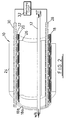
- Figure 1 of the drawings shows a tubular protective sheath 10 in accordance with a preferred embodiment of the present invention, the sheath 10 providing a safety barrier around an optical fibre 12 (Figure 2) which acts as a power conduit between a high power laser 14 and one or more workstations 16 (only one shown).
- the energy carried by the optical fibre 12 is such that a fracture of the fibre 12 would result in immediate burning of the conduit and sheath and a consequential safety hazard to equipment and people.
- the present invention is intended to obviate or mitigate this hazard by providing means which permit the condition of the conduit to be monitored such that the supply of energy through the fibre 12 may be cut off if the integrity of the sheath 10 is compromised.
- the sheath 10 comprises: an outer jacket 24; a detection layer 18 having inner and outer tubular members 18a, 18b, formed of first and second respective elements in the form of tapes 20, 22 (shown in more detail in Figure 3 of the drawings) which are helically wound in overlapping relationship to form the inner and outer tubular members 18a, 18b; an inner tube 26; and conductive members in the form of drain wires 28, 30, which are connected to a monitoring circuit 32.
- the optical fibre 12 passes through the inner tube 26 and is of considerably smaller diameter than the sheath.
- the fibre may be retro-fitted in the sheath and the inner tube 26 is therefore of a low friction material, such as polytetrafluoroethylene (PTFE).
- PTFE polytetrafluoroethylene
- the inner tube 26 has a diameter of 3mm, whereas the optical fibre 12 has a diameter of 600 microns.
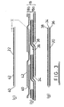
- the tubular members 18a, 18b formed by the tapes 20, 22 form a detection layer 18, each of the tapes 20, 22 being wound in overlapping relation. It is necessary for the tapes to overlap, as otherwise bends in the sheath would result in unacceptable gaps at the outer radius of the sheath.
- the first tape 20 is in the form of an electrically insulating film 34 having respective layers of electrically conductive low melt material 36, 38 adherent to its opposite surfaces.
- the second tape 22 is in the form of an electrically insulating film 40 having a layer 42 of electrically conductive low melt material adherent to one surface.
- the insulating films 34, 40 are preferably formed of Mylar and the low melt material forming the layers 36, 38, 42 is preferably carbon filled polyester, with a carbon loading of about 50% by weight to give a resistivity of approximately 0.3 - 0.4 ohms-cm.
- the second tape 22 overlies the first tape 20 with the low melt layer 42 spaced from the adjacent low melt layer 38 of the first tape by the insulating film 40.
- a fracture in the optical fibre 12 would lead to a hole being burned through the sheath, and when a hole is burned through the detection layer 18, the low melt material forming the layers 36, 38, 42 is fluidised and may thus flow to form an electrical connection between the respective layers 36, 38, 42 of the tapes 20, 22 and thus form a connection between the drain wires 28, 30, which connection is detected by the monitoring circuit 32 which in turn shuts off the laser 14.
- a fractured optical fibre would normally result in one or more holes being formed through the insulating film 34 in the first tape, and more importantly through the insulating film 40 on the second tape through which the low melt material may flow.
- the first tape 20 is overlapped such that the low melt material layers 36, 38 are in contact with one another and thus effectively form a single conductive member. It will also be noted that a gap X of 0.5 to 1mm is provided between the edges of the low melt material layer 42 and the adjacent edges of the insulating film 40 to prevent stray conduction between the tapes 20, 22. Layers 36, 38 may be similarly spaced from the edges of film 34.
- the sheath is likely to be of some length and thus it is in many cases necessary to provide drain wires 28, 30 to provide a low resistance path to the monitoring circuit 32. It is preferred to locate the wires 28, 30 on either side of the detection layer 18, and the inner low melt material layer 36 provides a conductive inner coating for the layer to form a connection with the wire 28.
- the wires 28, 30 are illustrated in the form of stranded metal, preferably copper, other configurations of conductor may be used such as a flat copper conductor, aluminium coated Mylar or a carbon filled PTFE strip. Where the conduit will be subject to flexure, it is necessary to provide flexible conductors which will not abrade or otherwise damage the detection layer 18. In such applications, helically wound carbon filled PFTE may be used.
- FIG. 4 of the drawings illustrates the monitoring circuit 32 in more detail.
- the circuit includes a relay 46 with normally open contacts 48 which, in normal operation, are held closed to complete a laser power control circuit (not shown).
- the relay coil 50 is supplied from a voltage source 52, through a current limiter 54, set slightly higher than the threshold to hold the contacts 48 closed.
- the coil 50 is also connected to the tapes 20, 22 via the drain wires 28, 30. In normal operation there is very high resistance between the wires 28, 30 (megohms per meter length) and an electrical connection between the tapes 20, 22 through flow of the low melt material 36, 38, 42 provides an electrical loop with a resistance of less than 1 kohm.
- the current from the source 52 is divided between the loop created by the fault and the relay coil 50 such that the current in the coil 50 is reduced below its threshold level and the contacts 48 open, switching off power to the circuit.
- the sheath described above provides means which will detect a break in the sheath due to the localised heating which results from a fracture in the optical fibre 12.
- the sheath will also similarly detect a hole being burned through the sheath from the outside of the sheath.
- first and second tapes may be arranged in different configurations, and the first tape could equally well form the outer tubular member and the second tape form the inner tubular member.
- the first tape may be solely of electrically conductive low melt material, and thus be in the form of a continuous tube.
Landscapes
- Physics & Mathematics (AREA)
- General Physics & Mathematics (AREA)
- Optics & Photonics (AREA)
- Rigid Pipes And Flexible Pipes (AREA)
- Details Of Indoor Wiring (AREA)
- Light Receiving Elements (AREA)
- Apparatus For Radiation Diagnosis (AREA)
- Surgical Instruments (AREA)
- Laminated Bodies (AREA)
Applications Claiming Priority (2)
| Application Number | Priority Date | Filing Date | Title |
|---|---|---|---|
| GB919115641A GB9115641D0 (en) | 1991-07-19 | 1991-07-19 | Protective sheath |
| GB9115641 | 1991-07-19 |
Publications (2)
| Publication Number | Publication Date |
|---|---|
| EP0524003A1 true EP0524003A1 (de) | 1993-01-20 |
| EP0524003B1 EP0524003B1 (de) | 1997-12-17 |
Family
ID=10698651
Family Applications (1)
| Application Number | Title | Priority Date | Filing Date |
|---|---|---|---|
| EP92306552A Expired - Lifetime EP0524003B1 (de) | 1991-07-19 | 1992-07-16 | Schutzhülle |
Country Status (7)
| Country | Link |
|---|---|
| US (1) | US5438474A (de) |
| EP (1) | EP0524003B1 (de) |
| DE (1) | DE69223555T2 (de) |
| DK (1) | DK0524003T3 (de) |
| ES (1) | ES2111049T3 (de) |
| GB (2) | GB9115641D0 (de) |
| NO (1) | NO304460B1 (de) |
Families Citing this family (3)
| Publication number | Priority date | Publication date | Assignee | Title |
|---|---|---|---|---|
| ES2119679B1 (es) * | 1996-02-27 | 1999-05-01 | Univ Malaga | Sensor para la proteccion de guias opticas contra roturas por flexion. |
| USD408365S (en) * | 1997-03-28 | 1999-04-20 | Sanders Robert A | Electrical cord protector |
| US11163127B2 (en) * | 2019-10-01 | 2021-11-02 | Ii-Vi Delaware, Inc. | Protective conduit for high-power laser applications in light guide cables |
Citations (2)
| Publication number | Priority date | Publication date | Assignee | Title |
|---|---|---|---|---|
| EP0317101A2 (de) * | 1987-11-19 | 1989-05-24 | W.L. Gore & Associates, Inc. | Sicherheitssystem und ein signaltragendes Glied dafür |
| US4859989A (en) * | 1987-12-01 | 1989-08-22 | W. L. Gore & Associates, Inc. | Security system and signal carrying member thereof |
Family Cites Families (9)
| Publication number | Priority date | Publication date | Assignee | Title |
|---|---|---|---|---|
| AT315019B (de) * | 1971-02-23 | 1974-05-10 | Gao Ges Automation Org | Sicherheitsbehälter od.dgl. |
| US3956726A (en) * | 1974-12-23 | 1976-05-11 | Cerro Corporation | Heat detecting conductor and circuit |
| JPS59225943A (ja) * | 1983-06-06 | 1984-12-19 | 日東電工株式会社 | 低融点金属フオ−ム |
| FR2592268B1 (fr) * | 1985-12-20 | 1988-10-28 | Philips Ind Commerciale | Enceinte protegee avec interrupteur electrique et son application |
| WO1987006749A1 (en) * | 1986-05-03 | 1987-11-05 | Adrian Francis Wolf | Alarm system |
| NL8700165A (nl) * | 1987-01-23 | 1988-08-16 | Seculock B V I O | Cheques- en creditcards-opberginrichting met ingebouwd vernietigingssysteem. |
| GB8814471D0 (en) * | 1988-06-17 | 1988-07-20 | Gore & Ass | Security enclosure |
| US5228478A (en) * | 1989-02-01 | 1993-07-20 | Kleisle James R | Wear indicator for material transfer systems |
| GB9012272D0 (en) * | 1990-06-01 | 1990-07-18 | Gore W L & Ass Uk | Flexible sheeting |
-
1991
- 1991-07-19 GB GB919115641A patent/GB9115641D0/en active Pending
-
1992
- 1992-07-16 DE DE69223555T patent/DE69223555T2/de not_active Expired - Fee Related
- 1992-07-16 GB GB9215092A patent/GB2258948B/en not_active Revoked
- 1992-07-16 DK DK92306552T patent/DK0524003T3/da active
- 1992-07-16 EP EP92306552A patent/EP0524003B1/de not_active Expired - Lifetime
- 1992-07-16 ES ES92306552T patent/ES2111049T3/es not_active Expired - Lifetime
- 1992-07-17 NO NO922839A patent/NO304460B1/no not_active IP Right Cessation
-
1994
- 1994-06-24 US US08/265,055 patent/US5438474A/en not_active Expired - Fee Related
Patent Citations (2)
| Publication number | Priority date | Publication date | Assignee | Title |
|---|---|---|---|---|
| EP0317101A2 (de) * | 1987-11-19 | 1989-05-24 | W.L. Gore & Associates, Inc. | Sicherheitssystem und ein signaltragendes Glied dafür |
| US4859989A (en) * | 1987-12-01 | 1989-08-22 | W. L. Gore & Associates, Inc. | Security system and signal carrying member thereof |
Non-Patent Citations (3)
| Title |
|---|
| PATENT ABSTRACTS OF JAPAN vol. 14, no. 405 (P-1100)31 August 1990 & JP-A-2 157 710 ( MATSUSHITA ELECTRIC ) 18 June 1990 * |
| PATENT ABSTRACTS OF JAPAN vol. 7, no. 245 (P-233)(1390) 29 October 1983 & JP-A-58 130 301 ( FURUKAWA ) 3 August 1983 * |
| PATENT ABSTRACTS OF JAPAN vol. 9, no. 285 (P-404)(2008) 12 November 1985 & JP-A-60 125 806 ( AROKA ) 5 July 1985 * |
Also Published As
| Publication number | Publication date |
|---|---|
| GB9115641D0 (en) | 1991-09-04 |
| US5438474A (en) | 1995-08-01 |
| GB2258948A (en) | 1993-02-24 |
| EP0524003B1 (de) | 1997-12-17 |
| DK0524003T3 (da) | 1998-08-24 |
| ES2111049T3 (es) | 1998-03-01 |
| GB9215092D0 (en) | 1992-08-26 |
| DE69223555D1 (de) | 1998-01-29 |
| NO922839L (no) | 1993-01-20 |
| DE69223555T2 (de) | 1998-07-16 |
| NO922839D0 (no) | 1992-07-17 |
| NO304460B1 (no) | 1998-12-14 |
| GB2258948B (en) | 1995-08-16 |
Similar Documents
| Publication | Publication Date | Title |
|---|---|---|
| US6801117B2 (en) | Fault sensing wire and alarm apparatus | |
| US6559437B1 (en) | Fiber optic damage sensor for wire and cable | |
| US4453159A (en) | Self-monitoring heat tracing system | |
| USRE38714E1 (en) | Electrical safety device | |
| US3551586A (en) | Shielded electrical cable | |
| US10830648B2 (en) | Abnormal temperature detection system, abnormal temperature detection cable and cable | |
| JPS63160189A (ja) | 電気加熱アッセンブリおよび電気ヒーター | |
| CN112816089B (zh) | 热感测导线及热感测技术 | |
| US4891500A (en) | Self-healing parallel heating tape | |
| US5438474A (en) | Protective sheath | |
| US6207902B1 (en) | Electrical wiring cable with color contrast abrasion wear indicator | |
| EP1645167B1 (de) | Heizdecke | |
| EP0317101B1 (de) | Sicherheitssystem und ein signaltragendes Glied dafür | |
| EP1662288B1 (de) | Schutzeinrichtung für Lichtleitfasern | |
| US4129894A (en) | Laminated current surge protector | |
| US3956726A (en) | Heat detecting conductor and circuit | |
| US20100142584A1 (en) | Digital linear heat detector with thermal activation confirmation | |
| US3160871A (en) | Tap-proof security communications cable | |
| EP0095315B1 (de) | Wärmeempfindlicher Leitungsunterbrecher | |
| US20040252429A1 (en) | Line arrangement for electrical systems of vehicles | |
| JPH01283710A (ja) | 超電導送電ケーブル及び送電方法 | |
| JP3346463B2 (ja) | 車両用電源線及び車両用電源線の異常検出装置 | |
| JP2010003569A (ja) | ヒーター線 | |
| CN118448101A (zh) | 一种线型光敏火灾探测器线缆 | |
| ITVR980073A1 (it) | Rilevatore di temperatura associato ai morsetti di collegamento di apparecchiature elettriche modulari. |
Legal Events
| Date | Code | Title | Description |
|---|---|---|---|
| PUAI | Public reference made under article 153(3) epc to a published international application that has entered the european phase |
Free format text: ORIGINAL CODE: 0009012 |
|
| AK | Designated contracting states |
Kind code of ref document: A1 Designated state(s): DE DK ES FR GB IT SE |
|
| 17P | Request for examination filed |
Effective date: 19930624 |
|
| RIN1 | Information on inventor provided before grant (corrected) |
Inventor name: PARSONS, CHRISTOPHER FREDERICK Inventor name: CROXFORD, NEAL Inventor name: MCNAUGHTON, DAVID Inventor name: MACPHERSON, HUGH |
|
| 17Q | First examination report despatched |
Effective date: 19950314 |
|
| GRAG | Despatch of communication of intention to grant |
Free format text: ORIGINAL CODE: EPIDOS AGRA |
|
| GRAH | Despatch of communication of intention to grant a patent |
Free format text: ORIGINAL CODE: EPIDOS IGRA |
|
| GRAH | Despatch of communication of intention to grant a patent |
Free format text: ORIGINAL CODE: EPIDOS IGRA |
|
| GRAA | (expected) grant |
Free format text: ORIGINAL CODE: 0009210 |
|
| AK | Designated contracting states |
Kind code of ref document: B1 Designated state(s): DE DK ES FR GB IT SE |
|
| REF | Corresponds to: |
Ref document number: 69223555 Country of ref document: DE Date of ref document: 19980129 |
|
| ITF | It: translation for a ep patent filed | ||
| REG | Reference to a national code |
Ref country code: ES Ref legal event code: FG2A Ref document number: 2111049 Country of ref document: ES Kind code of ref document: T3 |
|
| ET | Fr: translation filed | ||
| REG | Reference to a national code |
Ref country code: DK Ref legal event code: T3 |
|
| PLBE | No opposition filed within time limit |
Free format text: ORIGINAL CODE: 0009261 |
|
| STAA | Information on the status of an ep patent application or granted ep patent |
Free format text: STATUS: NO OPPOSITION FILED WITHIN TIME LIMIT |
|
| 26N | No opposition filed | ||
| PGFP | Annual fee paid to national office [announced via postgrant information from national office to epo] |
Ref country code: SE Payment date: 20000703 Year of fee payment: 9 Ref country code: GB Payment date: 20000703 Year of fee payment: 9 Ref country code: DK Payment date: 20000703 Year of fee payment: 9 Ref country code: DE Payment date: 20000703 Year of fee payment: 9 |
|
| PGFP | Annual fee paid to national office [announced via postgrant information from national office to epo] |
Ref country code: FR Payment date: 20000706 Year of fee payment: 9 |
|
| PGFP | Annual fee paid to national office [announced via postgrant information from national office to epo] |
Ref country code: ES Payment date: 20000808 Year of fee payment: 9 |
|
| PG25 | Lapsed in a contracting state [announced via postgrant information from national office to epo] |
Ref country code: GB Free format text: LAPSE BECAUSE OF NON-PAYMENT OF DUE FEES Effective date: 20010716 Ref country code: DK Free format text: LAPSE BECAUSE OF NON-PAYMENT OF DUE FEES Effective date: 20010716 |
|
| PG25 | Lapsed in a contracting state [announced via postgrant information from national office to epo] |
Ref country code: SE Free format text: LAPSE BECAUSE OF NON-PAYMENT OF DUE FEES Effective date: 20010717 Ref country code: ES Free format text: LAPSE BECAUSE OF NON-PAYMENT OF DUE FEES Effective date: 20010717 |
|
| EUG | Se: european patent has lapsed |
Ref document number: 92306552.8 |
|
| GBPC | Gb: european patent ceased through non-payment of renewal fee |
Effective date: 20010716 |
|
| REG | Reference to a national code |
Ref country code: DK Ref legal event code: EBP |
|
| PG25 | Lapsed in a contracting state [announced via postgrant information from national office to epo] |
Ref country code: FR Free format text: LAPSE BECAUSE OF NON-PAYMENT OF DUE FEES Effective date: 20020329 |
|
| PG25 | Lapsed in a contracting state [announced via postgrant information from national office to epo] |
Ref country code: DE Free format text: LAPSE BECAUSE OF NON-PAYMENT OF DUE FEES Effective date: 20020501 |
|
| REG | Reference to a national code |
Ref country code: FR Ref legal event code: ST |
|
| REG | Reference to a national code |
Ref country code: ES Ref legal event code: FD2A Effective date: 20020810 |
|
| PG25 | Lapsed in a contracting state [announced via postgrant information from national office to epo] |
Ref country code: IT Free format text: LAPSE BECAUSE OF NON-PAYMENT OF DUE FEES;WARNING: LAPSES OF ITALIAN PATENTS WITH EFFECTIVE DATE BEFORE 2007 MAY HAVE OCCURRED AT ANY TIME BEFORE 2007. THE CORRECT EFFECTIVE DATE MAY BE DIFFERENT FROM THE ONE RECORDED. Effective date: 20050716 |