EP0524445A1 - Roll-up entrance foot mat - Google Patents
Roll-up entrance foot mat Download PDFInfo
- Publication number
- EP0524445A1 EP0524445A1 EP92110664A EP92110664A EP0524445A1 EP 0524445 A1 EP0524445 A1 EP 0524445A1 EP 92110664 A EP92110664 A EP 92110664A EP 92110664 A EP92110664 A EP 92110664A EP 0524445 A1 EP0524445 A1 EP 0524445A1
- Authority
- EP
- European Patent Office
- Prior art keywords
- tread
- coupling
- rail
- members
- further characterized
- Prior art date
- Legal status (The legal status is an assumption and is not a legal conclusion. Google has not performed a legal analysis and makes no representation as to the accuracy of the status listed.)
- Granted
Links
Images

Classifications
-
- A—HUMAN NECESSITIES
- A47—FURNITURE; DOMESTIC ARTICLES OR APPLIANCES; COFFEE MILLS; SPICE MILLS; SUCTION CLEANERS IN GENERAL
- A47G—HOUSEHOLD OR TABLE EQUIPMENT
- A47G27/00—Floor fabrics; Fastenings therefor
- A47G27/06—Stair rods; Stair-rod fasteners ; Laying carpeting on stairs
-
- A—HUMAN NECESSITIES
- A47—FURNITURE; DOMESTIC ARTICLES OR APPLIANCES; COFFEE MILLS; SPICE MILLS; SUCTION CLEANERS IN GENERAL
- A47L—DOMESTIC WASHING OR CLEANING; SUCTION CLEANERS IN GENERAL
- A47L23/00—Cleaning footwear
- A47L23/22—Devices or implements resting on the floor for removing mud, dirt, or dust from footwear
- A47L23/26—Mats or gratings combined with brushes ; Mats
-
- Y—GENERAL TAGGING OF NEW TECHNOLOGICAL DEVELOPMENTS; GENERAL TAGGING OF CROSS-SECTIONAL TECHNOLOGIES SPANNING OVER SEVERAL SECTIONS OF THE IPC; TECHNICAL SUBJECTS COVERED BY FORMER USPC CROSS-REFERENCE ART COLLECTIONS [XRACs] AND DIGESTS
- Y10—TECHNICAL SUBJECTS COVERED BY FORMER USPC
- Y10T—TECHNICAL SUBJECTS COVERED BY FORMER US CLASSIFICATION
- Y10T428/00—Stock material or miscellaneous articles
- Y10T428/17—Three or more coplanar interfitted sections with securing means
-
- Y—GENERAL TAGGING OF NEW TECHNOLOGICAL DEVELOPMENTS; GENERAL TAGGING OF CROSS-SECTIONAL TECHNOLOGIES SPANNING OVER SEVERAL SECTIONS OF THE IPC; TECHNICAL SUBJECTS COVERED BY FORMER USPC CROSS-REFERENCE ART COLLECTIONS [XRACs] AND DIGESTS
- Y10—TECHNICAL SUBJECTS COVERED BY FORMER USPC
- Y10T—TECHNICAL SUBJECTS COVERED BY FORMER US CLASSIFICATION
- Y10T428/00—Stock material or miscellaneous articles
- Y10T428/18—Longitudinally sectional layer of three or more sections
Definitions
- a type of entrance foot mat that has become increasingly popular in the nearly twenty years since it was first introduced is one composed of elongated rail members joined together in side-by-side parallel relation by a coupling arrangement that allows the mat to be rolled up.
- C/S Construction Specialties, Inc.
- Pedimat® The first version of the "Pedimat®" foot mat, which is disclosed in U. S. patent no.
- 3,808,628 (Betts, May 7, 1974), comprised extruded aluminum rails joined by flexible strips that ran continuously crosswise of the rails and were joined to the rails by reception in slots in dependant side flanges of the rails having edge tabs that were crimped into engagement with the strips.
- the rails were spaced apart to provide gaps between adjacent rails into which dirt and water removed by the tread surfaces of the rails, which were strips of carpet, from the footwear of persons who walked across the mat could collect. Periodic cleaning of the mat and the floor under it was facilitated by rolling up the mat. The mat served its purpose of removing dirt and water very well, and the use of carpet as the tread surface made the mat aesthetically attractive.
- the only shortcoming of the original "Pedimat®" was a lack of durability -- the flexible strips that held the rails together often tore, causing the mat to gradually break up, and the rails were sometimes bent in between the rubber strips under unusually heavy loads.
- the present "Pedimat®" foot mats come in three styles, one with a carpet tread member, another with a vinyl tread member and the third with a grit tread member.
- the tread members are inserts in an extruded rail member that is used in all three versions.
- One object of the present invention is to provide a roll-up entrance foot mat that is has a durability comparable to all-aluminum mats.
- a further object is to provide a highly durable mat that is significantly less expensive to produce than all-aluminum mats are.
- Still another object is to provide a foot mat that does not rattle when walked upon.
- a roll-up entrance foot mat composed of a multiplicity of elongated extruded rail members joined side by side in parallel relation by elongated extruded coupling members, each rail member having along each edge a substantially longitudinally continuous coupling portion that engages a mating coupling portion on the adjacent coupling member such that the rail members articulate relative to the coupling members so that the mat can be rolled up.
- Each rail member has a tread-supporting portion that receives a tread member.
- the present invention is characterized in that the rail members are formed by coextrusion of a substantially rigid polymeric material and a compressible polymeric material. The tread-supporting web portion of each rail member is formed of the substantially rigid material.
- Each rail member has at least two leg portions of the substantially rigid material depending from the bottom of the tread-supporting web portion, the leg portions being laterally spaced apart from each other, substantially coextensive with the tread-supporting web portion, and adapted to support the tread-supporting web portion stably on a surface.
- Each rail member has a cushion portion of the compressible material on the bottom of each leg portion.
- the coupling portions of each rail member are of the substantially rigid material and are of a bulbous shape.
- Each coupling member has a web portion and a substantially longitudinally continuous socket portion on each side of the web portion, each socket portion defining an undercut groove that opens generally laterally outwardly with respect to the web portion and receives a bulbous coupling portion of an adjacent rail member such that adjacent rail members are coupled to each other by a coupling member for articulation, whereby the mat can be rolled up.
- each tread member is substantially coextensive both laterally and longitudinally of the tread-supporting web portion of the rail member on which it is received.
- Each socket portion of each coupling member has an upper tread surface that is generally level with the upper tread surface of the tread members of the mat. The upper tread surface of each socket portion is, preferably, treated to impart slip-resistance to it.
- each rail member include a side leg portion on each side, each such side leg portion having a lower part that extends laterally outwardly with respect to the tread-supporting web portion so as to underlie a corresponding coupling portion of a coupling member.
- a lowermost part of each socket portion of each coupling member is in close vertical clearance with an outwardly extending part of the side leg portion of the rail member to which it is joined so that a downward load on the coupling member is transferred from the lower part of each socket portion to a lower part of a side leg portion and thence to the surface upon which the mat is resting and lateral rocking motions of the rail members under downward loads on the coupling members are minimized.
- Metals suitable for the foot mat are significantly more expensive than suitable polymeric materials, such as polyvinyl chloride.
- suitable polymeric materials such as polyvinyl chloride.
- the rail members which are much larger in size than the coupling members, of polymeric materials and making the coupling members of a suitable metal, such as aluminum, bronze or stainless steel, a substantial cost benefit, as compared to metal rail members and coupling members of polymeric material or all metal mats, is obtained.
- the connections between the members are metal to polymeric material, which substantially eliminates the noise problem that exists in all-metal mats.
- the present invention eliminates the exposure of polymeric material to wear from being walked upon, inasmuch as the tread members cover substantially all of the surface of the polymeric material rail members and the metal coupling members have upper tread portions generally level with the upper surfaces of the tread members that are more resistant to wear from being walked upon, as compared to polymeric material.
- the durability of a mat, according to the present invention is generally greater than that of roll-up mats of the type that rely on flexible (bendable) coupling members, which are prone to fatigue failure from repeated bending.
- the capability of a mat according to the invention of being rolled up results entirely from the articulating, hinge-like action of the ball and socket connections between the rail members and the coupling members.
- the coupling members are of polymeric material
- Such grit layers impart a non-slip property to the tread surfaces and increase the resistance of the coupling members to wear.
- a roll-up entrance foot mat comprises a multiplicity of identical elongated rail members 10, each of which has a tread member 12 affixed to its upper surface, and a multiplicity of identical coupling members 14, each of which joins a pair of rail members to each other in side-by-side, parallel relation.
- Any number of rail members of any practical length can be joined to make up a mat of any desired size and shape, and the mats can be spliced in the field upon installation laterally or longitudinally in ways presently known in the art.
- the rail members 10 which are of various, interchangeable designs, are formed by coextrusion of a substantially rigid polymeric material, such as polyvinyl chloride, and a compressible polymeric material, such as a thermoplastic rubber.
- Each rail member has a tread-supporting web portion 16 of the substantially rigid polymeric material.
- Two generally L-shaped side leg portions 18 and 20 and a central, generally T-shaped leg portion 22, which are also formed of the substantially rigid polymeric material, extend continuously along the underside of the tread-supporting web portion 16.
- Cushion portions 24, 26, and 28 formed of the compressible polymeric material and extending along the bottom surfaces of the leg portions impart a non-slip property to the mat and also are somewhat compliant to irregularities in the surface on which the mat rests.
- a pair of coupling portions 30 and 32 of the substantially rigid polymeric material one on each side of the tread-supporting web portion and each substantially longitudinally coextensive with the tread-supporting web portion 16 and of a bulbous shape, extend generally laterally outwardly from the tread-supporting web portion.
- the tread member 12 supported on each rail member may be a strip of carpet (as shown in Figs. 1 and 2), a band of polymeric material having a layer of grit material adhered to it (Fig. 6), or a band of a polymeric material formed with a roughened surface (Fig. 7).
- the tread member is either suitably fastened to the rail member, such as by an adhesive, a fusion or chemical bond, or mechanical fasteners, or is integrally formed with it and is substantially coextensive with the upper surface of the web portion in both the transverse and longitudinal directions.
- the coupling members 14 are formed by extrusion of a metal, such as aluminum, bronze or stainless steel (Fig. 4), or of a substantially rigid polymeric material, such as polyvinyl chloride (Fig. 8).
- Each coupling member has a web portion 34 and a substantially longitudinally continuous socket portion 36 and 38, one on each side of the web portion.
- Each socket portion has an undercut groove 36a, 38a that opens generally laterally outwardly with respect to the web portion and receives a coupling portion 30 or 32 of an adjacent rail member such that adjacent rail members are coupled to each other by a coupling member for articulation (see Fig. 2) so that the mat can be rolled up for shipment, for cleaning of the surface under it and for convenient removal and transport to another location for cleaning.
- An upper tread surface 40, 42 that is generally level with the upper tread surfaces of the tread members 12 of the mat is provided on the upwardly facing surface of each of the coupling portions 36 and 38.
- Each tread surface has either integrally formed ribs (Fig. 4) or an adhesively or thermally bonded layer of abrasive grit material (Fig. 8) that imparts a non-slip property to it and enhances its wearability.
- Longitudinally spaced-apart holes or slots 44 formed in the web portion 34 of each coupling member provide for the passage of dirt and water from the spaces between the rail members and above the web portion onto the surface on which the mat is supported and thereby increase the dirt-capturing and storing capability of the mat.
- each socket portion 36, 38 of each coupling member 14 is in close vertical clearance with an outwardly extending part of the side leg portion of the rail member to which it is joined so that a downward load on the coupling member is transferred from the lower part of each socket portion to a leg portion of the rail member and thence to a surface upon which the mat is resting, and lateral rocking motions of the rail members under downward loads on the coupling members are minimized.
- the rail member of Fig. 3 has inturned lip portions 50, 52 along each side of the web portion 16 that define grooves 54, 56 for capturing a semi-rigid backing of a replaceable carpet strip, which serves as the tread member in this form of rail (see Fig. 2).
- the carpet strips are mechanically fastened to the rails, such as by rivets or staples, to keep them in place endwise.
- the rail member of Fig. 5 has a small shoulder 60, 62 along each side of the upper surface of the web portion 16 for locating the proper position of a carpet strip (not shown) that is adhesively or thermally bonded to the upper surface of the web portion.
- An integrally formed band 70 of the same polymeric material as the tread-supporting web portion 16 over-lies the tread-supporting web portion 16 in the rail member shown in Fig. 6.
- Small ribs 72, 74 along each side of the band 70 form a trough on the upper surface of the band for reception of a layer 76 of an abrasive grit material that is adhesively or thermally bonded to the upper surface of the band and serves as the tread member.
- the tread member 12 of a mat made from the rail member shown in Fig. 7 is an integral band 80 of a polymeric material, such as a flexible polyvinyl chloride, that is coextruded with the rail member and has protuberances 82 on its upper surface that give it a non-slip property.
- the material of the band may be compounded to be softer than that of the rail member in order to impart some resilience to it for a cushioning effect when it is walked on.
- any of the four rail members and the corresponding tread members of Fig. 3, 5, 6 and 7 and either of the two coupling members of Figs. 4 and 8 can be used to make up a mat, which gives the architect or designer considerable freedom to select an aesthetically and functionally suitable design from numerous possibilities.
- the colors of the tread members, rail members, and coupling members can, of course, also be varied.
Landscapes
- Carpets (AREA)
- Replacement Of Web Rolls (AREA)
- Passenger Equipment (AREA)
- Floor Finish (AREA)
- Machines For Manufacturing Corrugated Board In Mechanical Paper-Making Processes (AREA)
- Absorbent Articles And Supports Therefor (AREA)
- Bathtub Accessories (AREA)
- Support Devices For Sliding Doors (AREA)
Abstract
Description
- A type of entrance foot mat that has become increasingly popular in the nearly twenty years since it was first introduced is one composed of elongated rail members joined together in side-by-side parallel relation by a coupling arrangement that allows the mat to be rolled up. As far as the present applicant is aware, the first mat of this type to be marketed widely was introduced in the early 1970's by Construction Specialties, Inc. ("C/S"), the assignee of the present invention, under the trademark "Pedimat®." The first version of the "Pedimat®" foot mat, which is disclosed in U. S. patent no. 3,808,628 (Betts, May 7, 1974), comprised extruded aluminum rails joined by flexible strips that ran continuously crosswise of the rails and were joined to the rails by reception in slots in dependant side flanges of the rails having edge tabs that were crimped into engagement with the strips. The rails were spaced apart to provide gaps between adjacent rails into which dirt and water removed by the tread surfaces of the rails, which were strips of carpet, from the footwear of persons who walked across the mat could collect. Periodic cleaning of the mat and the floor under it was facilitated by rolling up the mat. The mat served its purpose of removing dirt and water very well, and the use of carpet as the tread surface made the mat aesthetically attractive. The only shortcoming of the original "Pedimat®" was a lack of durability -- the flexible strips that held the rails together often tore, causing the mat to gradually break up, and the rails were sometimes bent in between the rubber strips under unusually heavy loads.
- In 1975, C/S introduced a new version of the "Pedimat®" entrance foot mat, which is disclosed in U.S. patent no. 4,029,834 (Bartlett, June 14, 1977) and is still being marketed. In that version, elongated extruded aluminum rails are joined together side-by-side by in a hinge-like fashion by longitudinally continuous ball and socket coupling arrangements that are integral with the rails; a ball on one rail is received in a socket on an adjacent rail. The ball portions of the rails are joined to the tread portions by a web portion that has holes or slots through which dirt and water from the footwear of persons who walk across the mat fall to the floor under the mat. The present "Pedimat®" foot mats come in three styles, one with a carpet tread member, another with a vinyl tread member and the third with a grit tread member. The tread members are inserts in an extruded rail member that is used in all three versions.
- Variations of the "Pedimat®" mats have been proposed, and some of the variations have been commercialized. The following U. S. patents describe and show mats similar to the all aluminum "Pedimat®" mat product:
No. Re. 32,061 (Ellingson, Jr., Jan. 7, 1986) -- extruded aluminum rails having sockets along each side joined by extruded aluminum hinge members of a "dogbone" cross section; No. 4,568,587 (Balzer, Feb. 4, 1986) --extruded aluminum rails with sockets along each side joined by coupling members of a flexible, extruded polymeric material, such a polyvinyl chloride, that enable the mat to be rolled up by bending of the hinge members; No. 4,877,672 (Shreiner, Oct. 31, 1989) -- rail members tri-extruded from soft and hard polymeric materials, joined by integral balls and sockets and having living hinges formed in web portions by which the ball portions are joined to the tread portions of the rails. (C/S markets this product at the present time under the trademark "Treadline®").
No. 4,590,110 (Arens, May 20, 1986) -- brush-like tread members received in metal pans that are in turn inserted into rail members of a polymeric material, which are coupled together by metal coupling members. - Although roll-up entrance mats that include rail members or hinge members of polymeric materials are attractive and usually less expensive than all-aluminum mats, the all-aluminum mats are more durable and are considered by some people to be more attractive, because the aluminum provides a decorative accent. On the other hand, the all aluminum mats tend to rattle when walked across due to the metal-to-metal contact between the balls and sockets and some looseness in the ball and socket couplings, the looseness being inevitable because the fit between the balls and sockets has to be such that the rails can be slid together at assembly and the couplings can rotate.
- One object of the present invention is to provide a roll-up entrance foot mat that is has a durability comparable to all-aluminum mats. A further object is to provide a highly durable mat that is significantly less expensive to produce than all-aluminum mats are. Still another object is to provide a foot mat that does not rattle when walked upon.
- The foregoing and other objects are attained, in accordance with the present invention, by a roll-up entrance foot mat composed of a multiplicity of elongated extruded rail members joined side by side in parallel relation by elongated extruded coupling members, each rail member having along each edge a substantially longitudinally continuous coupling portion that engages a mating coupling portion on the adjacent coupling member such that the rail members articulate relative to the coupling members so that the mat can be rolled up. Each rail member has a tread-supporting portion that receives a tread member. The present invention is characterized in that the rail members are formed by coextrusion of a substantially rigid polymeric material and a compressible polymeric material. The tread-supporting web portion of each rail member is formed of the substantially rigid material. Each rail member has at least two leg portions of the substantially rigid material depending from the bottom of the tread-supporting web portion, the leg portions being laterally spaced apart from each other, substantially coextensive with the tread-supporting web portion, and adapted to support the tread-supporting web portion stably on a surface. Each rail member has a cushion portion of the compressible material on the bottom of each leg portion. The coupling portions of each rail member are of the substantially rigid material and are of a bulbous shape. Each coupling member has a web portion and a substantially longitudinally continuous socket portion on each side of the web portion, each socket portion defining an undercut groove that opens generally laterally outwardly with respect to the web portion and receives a bulbous coupling portion of an adjacent rail member such that adjacent rail members are coupled to each other by a coupling member for articulation, whereby the mat can be rolled up.
- In a preferred embodiment, each tread member is substantially coextensive both laterally and longitudinally of the tread-supporting web portion of the rail member on which it is received. Each socket portion of each coupling member has an upper tread surface that is generally level with the upper tread surface of the tread members of the mat. The upper tread surface of each socket portion is, preferably, treated to impart slip-resistance to it.
- It is also preferable that each rail member include a side leg portion on each side, each such side leg portion having a lower part that extends laterally outwardly with respect to the tread-supporting web portion so as to underlie a corresponding coupling portion of a coupling member. A lowermost part of each socket portion of each coupling member is in close vertical clearance with an outwardly extending part of the side leg portion of the rail member to which it is joined so that a downward load on the coupling member is transferred from the lower part of each socket portion to a lower part of a side leg portion and thence to the surface upon which the mat is resting and lateral rocking motions of the rail members under downward loads on the coupling members are minimized.
- Metals suitable for the foot mat are significantly more expensive than suitable polymeric materials, such as polyvinyl chloride. By making the rail members, which are much larger in size than the coupling members, of polymeric materials and making the coupling members of a suitable metal, such as aluminum, bronze or stainless steel, a substantial cost benefit, as compared to metal rail members and coupling members of polymeric material or all metal mats, is obtained. In such embodiments of a mat according to the present invention, the connections between the members are metal to polymeric material, which substantially eliminates the noise problem that exists in all-metal mats. The present invention, in preferred embodiments, eliminates the exposure of polymeric material to wear from being walked upon, inasmuch as the tread members cover substantially all of the surface of the polymeric material rail members and the metal coupling members have upper tread portions generally level with the upper surfaces of the tread members that are more resistant to wear from being walked upon, as compared to polymeric material. The durability of a mat, according to the present invention, is generally greater than that of roll-up mats of the type that rely on flexible (bendable) coupling members, which are prone to fatigue failure from repeated bending. The capability of a mat according to the invention of being rolled up results entirely from the articulating, hinge-like action of the ball and socket connections between the rail members and the coupling members.
- In embodiments in which the coupling members are of polymeric material, it is advantageous to provide on the upper tread surfaces layers of an abrasive grit material. Such grit layers impart a non-slip property to the tread surfaces and increase the resistance of the coupling members to wear.
- For a better understanding of the invention, reference may be made to the following description of an exemplary embodiment, taken in conjunction with the accompanying drawings.
-
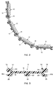
- Fig. 1 is a plan view of a segment of a mat embodying the invention;
- Fig. 2 is an end view of a segment of the mat of Fig. 1, a portion of the mat being shown rolled up;
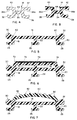
- Fig. 3 is a transverse cross-sectional view of an embodiment of a rail member of the mat that is designed to receive as the tread member a replaceable carpet strip;
- Fig. 4 is a transverse cross-sectional view of a metal coupling member;
- Fig. 5 is a transverse cross-sectional view of an embodiment of a rail member of the mat that is designed to receive as the tread member a carpet strip that is adhesively bonded to the tread-supporting web portion;
- Fig. 6 is a transverse cross-sectional view of an embodiment of a rail member of the mat that is designed to receive as the tread member a layer of an abrasive grit material adhesively bonded to the tread-supporting web portion;
- Fig. 7 is a transverse cross-sectional view of an embodiment of a rail member of the mat that has an integrally formed flexible tread member; and
- Fig. 8 is a transverse cross-sectional view of a coupling member of polymeric material.
- A roll-up entrance foot mat, according to the present invention, comprises a multiplicity of identical
elongated rail members 10, each of which has atread member 12 affixed to its upper surface, and a multiplicity ofidentical coupling members 14, each of which joins a pair of rail members to each other in side-by-side, parallel relation. Any number of rail members of any practical length (subject to manufacturing and shipping limitations) can be joined to make up a mat of any desired size and shape, and the mats can be spliced in the field upon installation laterally or longitudinally in ways presently known in the art. - The
rail members 10, which are of various, interchangeable designs, are formed by coextrusion of a substantially rigid polymeric material, such as polyvinyl chloride, and a compressible polymeric material, such as a thermoplastic rubber. Each rail member has a tread-supportingweb portion 16 of the substantially rigid polymeric material. Two generally L-shapedside leg portions leg portion 22, which are also formed of the substantially rigid polymeric material, extend continuously along the underside of the tread-supportingweb portion 16.Cushion portions coupling portions web portion 16 and of a bulbous shape, extend generally laterally outwardly from the tread-supporting web portion. - The
tread member 12 supported on each rail member may be a strip of carpet (as shown in Figs. 1 and 2), a band of polymeric material having a layer of grit material adhered to it (Fig. 6), or a band of a polymeric material formed with a roughened surface (Fig. 7). The tread member is either suitably fastened to the rail member, such as by an adhesive, a fusion or chemical bond, or mechanical fasteners, or is integrally formed with it and is substantially coextensive with the upper surface of the web portion in both the transverse and longitudinal directions. - The
coupling members 14 are formed by extrusion of a metal, such as aluminum, bronze or stainless steel (Fig. 4), or of a substantially rigid polymeric material, such as polyvinyl chloride (Fig. 8). Each coupling member has aweb portion 34 and a substantially longitudinallycontinuous socket portion groove coupling portion upper tread surface tread members 12 of the mat is provided on the upwardly facing surface of each of thecoupling portions slots 44 formed in theweb portion 34 of each coupling member provide for the passage of dirt and water from the spaces between the rail members and above the web portion onto the surface on which the mat is supported and thereby increase the dirt-capturing and storing capability of the mat. - As may best be seen in Fig. 3, the
bottom parts 18a and 20a of theside leg portions rail members 10 extend laterally outwardly with respect to the tread-supportingweb portion 16 so as to underlie acorresponding ball portion socket portion member 14 is in close vertical clearance with an outwardly extending part of the side leg portion of the rail member to which it is joined so that a downward load on the coupling member is transferred from the lower part of each socket portion to a leg portion of the rail member and thence to a surface upon which the mat is resting, and lateral rocking motions of the rail members under downward loads on the coupling members are minimized. - Except for differences in the tread-supporting web portions, the
rail members 10 shown in Fig. 3, 5, 6, and 7 are the same, and the corresponding portions are designated by the same reference numerals in those figures. - The rail member of Fig. 3 has inturned
lip portions web portion 16 that definegrooves - The rail member of Fig. 5 has a
small shoulder 60, 62 along each side of the upper surface of theweb portion 16 for locating the proper position of a carpet strip (not shown) that is adhesively or thermally bonded to the upper surface of the web portion. - An integrally formed
band 70 of the same polymeric material as the tread-supportingweb portion 16 over-lies the tread-supportingweb portion 16 in the rail member shown in Fig. 6.Small ribs band 70 form a trough on the upper surface of the band for reception of alayer 76 of an abrasive grit material that is adhesively or thermally bonded to the upper surface of the band and serves as the tread member. - The
tread member 12 of a mat made from the rail member shown in Fig. 7 is anintegral band 80 of a polymeric material, such as a flexible polyvinyl chloride, that is coextruded with the rail member and hasprotuberances 82 on its upper surface that give it a non-slip property. The material of the band may be compounded to be softer than that of the rail member in order to impart some resilience to it for a cushioning effect when it is walked on. - Any of the four rail members and the corresponding tread members of Fig. 3, 5, 6 and 7 and either of the two coupling members of Figs. 4 and 8 can be used to make up a mat, which gives the architect or designer considerable freedom to select an aesthetically and functionally suitable design from numerous possibilities. The colors of the tread members, rail members, and coupling members can, of course, also be varied.
Claims (14)
- A roll-up entrance foot mat composed of a multiplicity of elongated extruded rail members (10) joined side by side in parallel relation by elongated extruded coupling members (14), each rail member having along each edge a substantially longitudinally continuous coupling portion (30,32) that engages a mating coupling portion (36,38) on the adjacent coupling member such that the rail members articulate relative to the coupling members so that the mat can be rolled up, and each rail member having a tread-supporting portion (16) that receives a tread member (12,70,80), characterized in that the rail members (10) are formed by coextrusion of a substantially rigid polymeric material and a compressible polymeric material, in that the tread-supporting web portion (12) is formed of the substantially rigid material, in that each rail member has at least two leg portions (18,20) of the substantially rigid material depending from the bottom of the tread-supporting web portion, the leg portions being laterally spaced apart from each other, substantially coextensive with the tread-supporting web portion, and adapted to support the tread-supporting web portion stably on a surface, in that each rail member has a cushion portion (24,28) of the compressible material on the bottom of each leg portion, in that the coupling portions (30,32) of each rail member are of the substantially rigid material and are of a bulbous shape, and in that each coupling member (14) has a web portion (34) and a substantially longitudinally continuous socket portion (36,38) on each side of the web portion, each socket portion defining an undercut groove (36a,38a) that opens generally laterally outwardly with respect to the web portion and receives a bulbous coupling portion (30,32) of an adjacent rail member such that adjacent rail members are coupled to each other by a coupling member for articulation, whereby the mat can be rolled up.
- A foot mat according to claim 1 and further characterized in that each tread member (12,70,80) is substantially coextensive both laterally and longitudinally of the tread-supporting web portion (16) of the rail member on which it is received.
- A foot mat according to claim 2 and further characterized in that each socket portion (36,38) of each coupling member has an upper tread surface (40,42) that is generally level with the upper tread surface of the tread members of the mat.
- A foot mat according to claim 1 and further characterized in that each rail member (10) includes a side leg portion (18,20) on each side, each side leg portion having a lower part that extends laterally outwardly with respect to the tread-supporting web portion (16) so as to underlie a corresponding coupling portion (36,38) of a coupling member, and in that a lowermost part of each socket portion (36,38) of each coupling member is in close vertical clearance with an outwardly extending part of the side leg portion of the rail member to which it is joined so that a downward load on the coupling member is transferred from the lower part of each socket portion to a lower part of a side leg portion and thence to the surface upon which the mat is resting and lateral rocking motions of the rail members under downward loads on the coupling members are minimized.
- A foot mat according to claim 3 and further characterized in that each rail member (10) includes a side leg portion (18,20) on each side, each side leg portion having a lower part that extends laterally outwardly with respect to the tread-supporting web portion (16) so as to underlie a corresponding coupling portion (36,38) of a coupling member (14), and in that a lowermost part of each socket portion (36,38) of each coupling member (14) is in close vertical clearance with an outwardly extending part of the side leg portion (18,20) of the rail member to which it is joined so that a downward load on the coupling member is transferred from the lower part of each socket portion to a lower part of a side leg portion and thence to the surface upon which the mat is resting and lateral rocking motions of the rail members under downward loads on the coupling members are minimized.
- A foot mat according to claim 1 and further characterized in that each rail member (10) has inturned lip portions (50,52) along each side of the web portion (16) that define grooves (54,56) for capturing a semi-rigid backing of a replaceable carpet strip (12), which serves as the tread member.
- A foot mat according to claim 1 and further characterized in that each rail member (10) is adapted to receive as the tread member (12) a carpet strip that is adhesively or thermally bonded to the upper surface of the tread-supporting web portion.
- A foot mat according to claim 1 and further characterized in that the tread member (10) is an integrally formed band (70) of a polymeric material that overlies the tread-supporting web portion and has a layer (76) of an abrasive grit material that is bonded to the upper surface of the band.
- A foot mat according to claim 1 and further characterized in that the tread member (10) is an integral band (80) of a polymeric material that is coextruded with the rail member and has protuberances (82) on its upper surface that give it a non-slip property.
- A foot mat according to claim 9 and further characterized in that the material of the band (80) is compounded to be softer than that of the rail member (10) in order to impart some resilience to it for a cushioning effect when it is walked on.
- A foot mat according to claim 1 and further characterized in that each coupling member (14) is extruded from a metal.
- A foot mat according to claim 1 and further characterized in that each coupling member (14) is extruded from a substantially rigid polymeric material.
- A foot mat according to claim 3 and further characterized in that each coupling member (14) is extruded from a substantially rigid polymeric material.
- A foot mat according to claim 13 and further characterized in that each of the upper tread surfaces (40,42) of each coupling member (14) has a layer of an abrasive grit material bonded to it that imparts a non-slip property to the tread surface and increases wearability.
Applications Claiming Priority (2)
| Application Number | Priority Date | Filing Date | Title |
|---|---|---|---|
| US734552 | 1991-07-23 | ||
| US07/734,552 US5157804A (en) | 1991-07-23 | 1991-07-23 | Roll-up entrance foot mat |
Publications (2)
| Publication Number | Publication Date |
|---|---|
| EP0524445A1 true EP0524445A1 (en) | 1993-01-27 |
| EP0524445B1 EP0524445B1 (en) | 1995-10-11 |
Family
ID=24952156
Family Applications (1)
| Application Number | Title | Priority Date | Filing Date |
|---|---|---|---|
| EP92110664A Expired - Lifetime EP0524445B1 (en) | 1991-07-23 | 1992-06-25 | Roll-up entrance foot mat |
Country Status (10)
| Country | Link |
|---|---|
| US (1) | US5157804A (en) |
| EP (1) | EP0524445B1 (en) |
| JP (1) | JPH05192292A (en) |
| KR (1) | KR100270015B1 (en) |
| AT (1) | ATE128833T1 (en) |
| AU (1) | AU649334B2 (en) |
| CA (1) | CA2072715A1 (en) |
| DE (1) | DE69205358T2 (en) |
| ES (1) | ES2079104T3 (en) |
| HK (1) | HK24596A (en) |
Cited By (4)
| Publication number | Priority date | Publication date | Assignee | Title |
|---|---|---|---|---|
| DE4406093A1 (en) * | 1994-02-25 | 1995-09-07 | Aklass Haustechnik Gmbh | Foot=wiper mat with strips and scraper elements |
| NL1002694C2 (en) * | 1996-03-22 | 1997-09-23 | Jacobus Noels | Mat for building entrance |
| EP0882425A1 (en) * | 1997-06-07 | 1998-12-09 | Davero AG | Doormat |
| FR3161347A1 (en) | 2024-04-23 | 2025-10-24 | Gerflor | Aluminum profile of a modular floor mat, and mat incorporating such a profile |
Families Citing this family (51)
| Publication number | Priority date | Publication date | Assignee | Title |
|---|---|---|---|---|
| GB2257625B (en) * | 1991-07-18 | 1995-01-04 | Psa Threshold Ltd | Threshold mat |
| USD378645S (en) * | 1993-08-06 | 1997-04-01 | Btr Plc | Floor mat of tread strips with a spacer array |
| USD370817S (en) | 1993-08-06 | 1996-06-18 | Btr Plc | Tread strips for a floor mat |
| US5486392A (en) * | 1994-07-05 | 1996-01-23 | Reese Enterprises, Inc. | Roll-up floor mat |
| GB2297689B (en) * | 1995-02-07 | 1997-04-02 | Nuway Matting Systems Inc | Floor covering |
| US5833386A (en) * | 1995-10-25 | 1998-11-10 | Teletek Industries, Inc. | Modular roll-out portable floor and walkway |
| US5626933A (en) * | 1996-01-16 | 1997-05-06 | Long; Marcel | Modular floor cover |
| GB2314769B (en) * | 1996-07-05 | 2000-04-19 | Specialties Const | Matting system incorporating a scraper element |
| USD394776S (en) | 1996-09-23 | 1998-06-02 | Callas Mike T | Floor mat border |
| USD439462S1 (en) | 1996-09-23 | 2001-03-27 | Michael T. Callas | Floor mat border |
| US5870526A (en) * | 1997-07-17 | 1999-02-09 | Steag-Ast | Inflatable elastomeric element for rapid thermal processing (RTP) system |
| US5935676A (en) * | 1997-10-24 | 1999-08-10 | Merriman; Monte E. | Slip resistant roof mat |
| CA2318467C (en) * | 1998-01-07 | 2007-03-13 | Construction Specialties, Inc. | Foot mat |
| US6093469A (en) * | 1998-08-25 | 2000-07-25 | Callas; Michael T. | Mat and method of making mat |
| CN1191158C (en) | 1999-10-29 | 2005-03-02 | 新秀丽公司 | Direct molding of non-textile elements from thermoplastic particles or similar |
| US7807247B1 (en) | 1999-10-29 | 2010-10-05 | Bromley Robert L | Flexlock with headed pintle and conical buttressing |
| US6582797B1 (en) * | 2000-10-06 | 2003-06-24 | Springs Industries, Inc. | Carpet fringe and method of applying same |
| NL1016481C2 (en) * | 2000-10-25 | 2002-05-01 | Jacobus Noels | Mat for application at the entrance of a building. |
| US6640501B1 (en) * | 2002-04-23 | 2003-11-04 | Darren E. Hussey | Collapsible stair cover |
| US7108902B2 (en) * | 2004-02-03 | 2006-09-19 | Reese Enterprises, Inc. | Roll-up floor mat |
| US7748177B2 (en) | 2004-02-25 | 2010-07-06 | Connor Sport Court International, Inc. | Modular tile with controlled deflection |
| US7849642B2 (en) | 2004-03-12 | 2010-12-14 | Connor Sport Court International, Inc. | Tile with wide coupling configuration and method for the same |
| US7344197B2 (en) * | 2004-07-30 | 2008-03-18 | Brian Matthew Sanderson | Rollable supporting device |
| US7475933B2 (en) * | 2004-09-09 | 2009-01-13 | International Automotive Components Group North America, Inc. | Snap-in decorative articles for vehicle interiors |
| US8407951B2 (en) | 2004-10-06 | 2013-04-02 | Connor Sport Court International, Llc | Modular synthetic floor tile configured for enhanced performance |
| US8397466B2 (en) | 2004-10-06 | 2013-03-19 | Connor Sport Court International, Llc | Tile with multiple-level surface |
| EP1700559A1 (en) * | 2005-03-08 | 2006-09-13 | Gezu B.V. | Mat |
| USD656250S1 (en) | 2005-03-11 | 2012-03-20 | Connor Sport Court International, Llc | Tile with wide mouth coupling |
| US7543417B2 (en) | 2005-10-04 | 2009-06-09 | Comc, Llc | Modular flooring assemblies |
| GB0602553D0 (en) * | 2006-02-08 | 2006-03-22 | Cooper Lee | Modular flooring |
| US7774991B2 (en) * | 2006-10-04 | 2010-08-17 | Ground Floor Systems, Llc | Portable ground flooring systems and methods of assembling and packing same |
| US8438785B2 (en) * | 2008-06-16 | 2013-05-14 | Steven D. McDonough | Securable parapet cap roof mat |
| US20090311464A1 (en) * | 2008-06-16 | 2009-12-17 | Mcdonough Steven D | Securable Parapet Cap Roof Mat |
| US8205407B2 (en) * | 2009-04-15 | 2012-06-26 | Genova Michael C | Modular decking system |
| US8291670B2 (en) | 2009-04-29 | 2012-10-23 | E.M.E.H., Inc. | Modular entrance floor system |
| US8230654B2 (en) | 2009-06-10 | 2012-07-31 | Comc, Llc | Medallion insert for modular flooring assemblies |
| US8782989B2 (en) | 2009-06-11 | 2014-07-22 | Comc, Llc | Narrow lined modular flooring assemblies |
| WO2012159670A1 (en) * | 2011-05-24 | 2012-11-29 | Verimpex Nv | Profile for floor mats and mats produced thereof |
| US8784002B2 (en) | 2011-07-20 | 2014-07-22 | Property Props, Inc. | Track system for use with vehicles and methods regarding same |
| KR101105928B1 (en) | 2011-09-05 | 2012-01-17 | 이문기 | Slip resistant mat for rod |
| EP2606810A1 (en) | 2011-12-19 | 2013-06-26 | Forbo Flooring Coral N.V. | Floor mat |
| TW201346112A (en) * | 2012-05-11 | 2013-11-16 | Cehn Brothers Co Ltd | Quick assembling ground mat and part thereof |
| TWM458097U (en) * | 2013-04-01 | 2013-08-01 | Sekond Creative Design Co Ltd | Food thawing tray |
| US9340983B2 (en) | 2013-10-25 | 2016-05-17 | E.M.E.H., Inc. | Entrance floor system |
| AU2015301816B2 (en) * | 2014-08-12 | 2019-03-07 | Esco Group Llc | Wear surface |
| KR101470471B1 (en) * | 2014-09-23 | 2014-12-08 | 주식회사 화인 | A rigid inflatable boat having an air tube separable from a body of the boat |
| TWM503441U (en) * | 2015-02-06 | 2015-06-21 | Xigma Internat Co Ltd | Shock absorption soundproof pad structure |
| US12607021B2 (en) * | 2018-06-14 | 2026-04-21 | Société en Commandite Prolam | Slip-resistant floor for a cargo-carrying apparatus |
| EP3939487B1 (en) * | 2019-03-14 | 2026-04-01 | Basmat Matting Systems, S.L | Modular doormat |
| US12538983B2 (en) * | 2021-05-28 | 2026-02-03 | Alan Lamont | Rollable piece of furniture |
| KR102626625B1 (en) * | 2022-01-21 | 2024-01-19 | 김봉진 | Sterilization foothold using ultraviolet rays |
Citations (4)
| Publication number | Priority date | Publication date | Assignee | Title |
|---|---|---|---|---|
| USRE32061E (en) * | 1984-06-11 | 1986-01-07 | Reese Enterprises, Inc. | Coupling member for floor covering sections |
| US4568587A (en) * | 1981-09-25 | 1986-02-04 | Balco, Inc. | Roll-up floor mat with rigid rails |
| US4877672A (en) * | 1988-10-11 | 1989-10-31 | Construction Specialties, Inc. | Floor mat with rigid rails joined by living hinges |
| EP0351373A2 (en) * | 1988-07-11 | 1990-01-17 | Dell'Orto, Gianni | Modular element door mat |
Family Cites Families (9)
| Publication number | Priority date | Publication date | Assignee | Title |
|---|---|---|---|---|
| US2673365A (en) * | 1950-11-09 | 1954-03-30 | American Mat Corp | Floor mat |
| DE2112573C3 (en) * | 1971-03-16 | 1978-01-19 | Erich Arens | BAR GRATING, FOR EXAMPLE FOR WALKABLE COVERING OF GUTTERS OR THE SAME |
| US3783471A (en) * | 1971-11-19 | 1974-01-08 | Specialties Const | Foot grilles and mats |
| GB1605028A (en) * | 1978-04-21 | 1981-12-16 | Nuway Mfg Co Ltd | Mats |
| DE3317410A1 (en) * | 1983-05-13 | 1984-11-15 | Erich 5900 Siegen Arens | RUST FOR THE FORMATION OF TREADMats or doormats |
| US4654245A (en) * | 1984-08-29 | 1987-03-31 | Balco, Inc. | Roll up floor mat |
| US4675222A (en) * | 1986-06-30 | 1987-06-23 | Reese Enterprises, Inc. | Floor covering connecting and supporting structure |
| US4879151A (en) * | 1988-06-06 | 1989-11-07 | Reese Enterprises, Inc. | Insert strip for a floor covering structure |
| US4952434A (en) * | 1988-10-18 | 1990-08-28 | Balco International, Inc. | Cushioning floor mat |
-
1991
- 1991-07-23 US US07/734,552 patent/US5157804A/en not_active Expired - Lifetime
-
1992
- 1992-06-25 EP EP92110664A patent/EP0524445B1/en not_active Expired - Lifetime
- 1992-06-25 AU AU18594/92A patent/AU649334B2/en not_active Ceased
- 1992-06-25 AT AT92110664T patent/ATE128833T1/en not_active IP Right Cessation
- 1992-06-25 ES ES92110664T patent/ES2079104T3/en not_active Expired - Lifetime
- 1992-06-25 DE DE69205358T patent/DE69205358T2/en not_active Expired - Fee Related
- 1992-06-29 CA CA002072715A patent/CA2072715A1/en not_active Abandoned
- 1992-07-08 KR KR1019920012129A patent/KR100270015B1/en not_active Expired - Fee Related
- 1992-07-13 JP JP4185285A patent/JPH05192292A/en active Pending
-
1996
- 1996-02-08 HK HK24596A patent/HK24596A/en not_active IP Right Cessation
Patent Citations (4)
| Publication number | Priority date | Publication date | Assignee | Title |
|---|---|---|---|---|
| US4568587A (en) * | 1981-09-25 | 1986-02-04 | Balco, Inc. | Roll-up floor mat with rigid rails |
| USRE32061E (en) * | 1984-06-11 | 1986-01-07 | Reese Enterprises, Inc. | Coupling member for floor covering sections |
| EP0351373A2 (en) * | 1988-07-11 | 1990-01-17 | Dell'Orto, Gianni | Modular element door mat |
| US4877672A (en) * | 1988-10-11 | 1989-10-31 | Construction Specialties, Inc. | Floor mat with rigid rails joined by living hinges |
Cited By (5)
| Publication number | Priority date | Publication date | Assignee | Title |
|---|---|---|---|---|
| DE4406093A1 (en) * | 1994-02-25 | 1995-09-07 | Aklass Haustechnik Gmbh | Foot=wiper mat with strips and scraper elements |
| NL1002694C2 (en) * | 1996-03-22 | 1997-09-23 | Jacobus Noels | Mat for building entrance |
| EP0882425A1 (en) * | 1997-06-07 | 1998-12-09 | Davero AG | Doormat |
| FR3161347A1 (en) | 2024-04-23 | 2025-10-24 | Gerflor | Aluminum profile of a modular floor mat, and mat incorporating such a profile |
| EP4640131A1 (en) | 2024-04-23 | 2025-10-29 | Gerflor | Aluminium profile of a modular floor mat, and mat incorporating such a profile |
Also Published As
| Publication number | Publication date |
|---|---|
| EP0524445B1 (en) | 1995-10-11 |
| US5157804A (en) | 1992-10-27 |
| KR100270015B1 (en) | 2000-10-16 |
| KR930001854A (en) | 1993-02-22 |
| CA2072715A1 (en) | 1993-01-24 |
| JPH05192292A (en) | 1993-08-03 |
| HK24596A (en) | 1996-02-16 |
| AU1859492A (en) | 1993-01-28 |
| DE69205358D1 (en) | 1995-11-16 |
| AU649334B2 (en) | 1994-05-19 |
| ES2079104T3 (en) | 1996-01-01 |
| ATE128833T1 (en) | 1995-10-15 |
| DE69205358T2 (en) | 1996-04-04 |
Similar Documents
| Publication | Publication Date | Title |
|---|---|---|
| EP0524445B1 (en) | Roll-up entrance foot mat | |
| KR0129524B1 (en) | Floor mat with rigid rails joined by living hinges | |
| US5190799A (en) | Floor covering with integral walking surface | |
| US5486392A (en) | Roll-up floor mat | |
| US4663903A (en) | Floor covering structure | |
| AU736049B2 (en) | Foot mat | |
| US4568587A (en) | Roll-up floor mat with rigid rails | |
| EP0421258A1 (en) | Floor mat with rigid rails joined by living hinges | |
| US5351458A (en) | Spaced-plank floor system for animal enclosures | |
| US3808628A (en) | Floor mat | |
| CA3016525C (en) | Slidable anti-fatigue mat | |
| US7108902B2 (en) | Roll-up floor mat | |
| GB2199600A (en) | Anti-slip floor strip | |
| US7993726B2 (en) | Matting product | |
| KR100382595B1 (en) | Foot Grille | |
| MXPA05004963A (en) | Mat with elastic compressible elements. | |
| US3420015A (en) | Metal grating | |
| NZ547057A (en) | Flooring system | |
| GB2314769A (en) | Matting system | |
| EP1104830A2 (en) | Decking systems | |
| CN224170638U (en) | Ground mat based on bionic skin touch | |
| JP2002021302A (en) | Height variable indoor slope for difference in level | |
| CN2453718Y (en) | Shoe sole | |
| TWM449542U (en) | Composite structure member used in assembly-type floor mats and its assembly-type floor mats |
Legal Events
| Date | Code | Title | Description |
|---|---|---|---|
| PUAI | Public reference made under article 153(3) epc to a published international application that has entered the european phase |
Free format text: ORIGINAL CODE: 0009012 |
|
| AK | Designated contracting states |
Kind code of ref document: A1 Designated state(s): AT BE CH DE DK ES FR GB GR IT LI NL PT SE |
|
| 17P | Request for examination filed |
Effective date: 19930706 |
|
| 17Q | First examination report despatched |
Effective date: 19940526 |
|
| GRAA | (expected) grant |
Free format text: ORIGINAL CODE: 0009210 |
|
| ITF | It: translation for a ep patent filed | ||
| AK | Designated contracting states |
Kind code of ref document: B1 Designated state(s): AT BE CH DE DK ES FR GB GR IT LI NL PT SE |
|
| PG25 | Lapsed in a contracting state [announced via postgrant information from national office to epo] |
Ref country code: NL Free format text: LAPSE BECAUSE OF FAILURE TO SUBMIT A TRANSLATION OF THE DESCRIPTION OR TO PAY THE FEE WITHIN THE PRESCRIBED TIME-LIMIT Effective date: 19951011 Ref country code: CH Effective date: 19951011 Ref country code: GR Free format text: LAPSE BECAUSE OF FAILURE TO SUBMIT A TRANSLATION OF THE DESCRIPTION OR TO PAY THE FEE WITHIN THE PRESCRIBED TIME-LIMIT Effective date: 19951011 Ref country code: AT Effective date: 19951011 Ref country code: LI Effective date: 19951011 Ref country code: DK Effective date: 19951011 Ref country code: BE Effective date: 19951011 |
|
| REF | Corresponds to: |
Ref document number: 128833 Country of ref document: AT Date of ref document: 19951015 Kind code of ref document: T |
|
| REF | Corresponds to: |
Ref document number: 69205358 Country of ref document: DE Date of ref document: 19951116 |
|
| REG | Reference to a national code |
Ref country code: ES Ref legal event code: FG2A Ref document number: 2079104 Country of ref document: ES Kind code of ref document: T3 |
|
| PG25 | Lapsed in a contracting state [announced via postgrant information from national office to epo] |
Ref country code: PT Effective date: 19960111 Ref country code: SE Effective date: 19960111 |
|
| ET | Fr: translation filed | ||
| NLV1 | Nl: lapsed or annulled due to failure to fulfill the requirements of art. 29p and 29m of the patents act | ||
| REG | Reference to a national code |
Ref country code: CH Ref legal event code: PL |
|
| PLBE | No opposition filed within time limit |
Free format text: ORIGINAL CODE: 0009261 |
|
| STAA | Information on the status of an ep patent application or granted ep patent |
Free format text: STATUS: NO OPPOSITION FILED WITHIN TIME LIMIT |
|
| 26N | No opposition filed | ||
| REG | Reference to a national code |
Ref country code: FR Ref legal event code: CL Free format text: CORRECTION |
|
| REG | Reference to a national code |
Ref country code: GB Ref legal event code: IF02 |
|
| PGFP | Annual fee paid to national office [announced via postgrant information from national office to epo] |
Ref country code: ES Payment date: 20080626 Year of fee payment: 17 |
|
| PGFP | Annual fee paid to national office [announced via postgrant information from national office to epo] |
Ref country code: DE Payment date: 20080731 Year of fee payment: 17 |
|
| PGFP | Annual fee paid to national office [announced via postgrant information from national office to epo] |
Ref country code: IT Payment date: 20080627 Year of fee payment: 17 Ref country code: FR Payment date: 20080617 Year of fee payment: 17 |
|
| PGFP | Annual fee paid to national office [announced via postgrant information from national office to epo] |
Ref country code: GB Payment date: 20080627 Year of fee payment: 17 |
|
| GBPC | Gb: european patent ceased through non-payment of renewal fee |
Effective date: 20090625 |
|
| REG | Reference to a national code |
Ref country code: FR Ref legal event code: ST Effective date: 20100226 |
|
| PG25 | Lapsed in a contracting state [announced via postgrant information from national office to epo] |
Ref country code: FR Free format text: LAPSE BECAUSE OF NON-PAYMENT OF DUE FEES Effective date: 20090630 |
|
| PG25 | Lapsed in a contracting state [announced via postgrant information from national office to epo] |
Ref country code: GB Free format text: LAPSE BECAUSE OF NON-PAYMENT OF DUE FEES Effective date: 20090625 |
|
| PG25 | Lapsed in a contracting state [announced via postgrant information from national office to epo] |
Ref country code: DE Free format text: LAPSE BECAUSE OF NON-PAYMENT OF DUE FEES Effective date: 20100101 |
|
| REG | Reference to a national code |
Ref country code: ES Ref legal event code: FD2A Effective date: 20090626 |
|
| PG25 | Lapsed in a contracting state [announced via postgrant information from national office to epo] |
Ref country code: ES Free format text: LAPSE BECAUSE OF NON-PAYMENT OF DUE FEES Effective date: 20090626 |
|
| PG25 | Lapsed in a contracting state [announced via postgrant information from national office to epo] |
Ref country code: IT Free format text: LAPSE BECAUSE OF NON-PAYMENT OF DUE FEES Effective date: 20090625 |