EP0524657B1 - Protection pour bobines de fil - Google Patents
Protection pour bobines de fil Download PDFInfo
- Publication number
- EP0524657B1 EP0524657B1 EP92114175A EP92114175A EP0524657B1 EP 0524657 B1 EP0524657 B1 EP 0524657B1 EP 92114175 A EP92114175 A EP 92114175A EP 92114175 A EP92114175 A EP 92114175A EP 0524657 B1 EP0524657 B1 EP 0524657B1
- Authority
- EP
- European Patent Office
- Prior art keywords
- chuck
- package
- thread
- winder
- screening
- Prior art date
- Legal status (The legal status is an assumption and is not a legal conclusion. Google has not performed a legal analysis and makes no representation as to the accuracy of the status listed.)
- Expired - Lifetime
Links
Images


Classifications
-
- B—PERFORMING OPERATIONS; TRANSPORTING
- B65—CONVEYING; PACKING; STORING; HANDLING THIN OR FILAMENTARY MATERIAL
- B65H—HANDLING THIN OR FILAMENTARY MATERIAL, e.g. SHEETS, WEBS, CABLES
- B65H54/00—Winding, coiling, or depositing filamentary material
- B65H54/70—Other constructional features of yarn-winding machines
- B65H54/72—Framework; Casings; Coverings
-
- B—PERFORMING OPERATIONS; TRANSPORTING
- B65—CONVEYING; PACKING; STORING; HANDLING THIN OR FILAMENTARY MATERIAL
- B65H—HANDLING THIN OR FILAMENTARY MATERIAL, e.g. SHEETS, WEBS, CABLES
- B65H67/00—Replacing or removing cores, receptacles, or completed packages at paying-out, winding, or depositing stations
- B65H67/04—Arrangements for removing completed take-up packages and or replacing by cores, formers, or empty receptacles at winding or depositing stations; Transferring material between adjacent full and empty take-up elements
- B65H67/044—Continuous winding apparatus for winding on two or more winding heads in succession
- B65H67/052—Continuous winding apparatus for winding on two or more winding heads in succession having two or more winding heads arranged in parallel to each other
-
- B—PERFORMING OPERATIONS; TRANSPORTING
- B65—CONVEYING; PACKING; STORING; HANDLING THIN OR FILAMENTARY MATERIAL
- B65H—HANDLING THIN OR FILAMENTARY MATERIAL, e.g. SHEETS, WEBS, CABLES
- B65H2701/00—Handled material; Storage means
- B65H2701/30—Handled filamentary material
- B65H2701/31—Textiles threads or artificial strands of filaments
Definitions
- the present invention relates to developments in winders for synthetic filament.
- each chuck normally carries a plurality (usually up to 8) bobbin tubes during any given winding operation, and a corresponding number of thread packages are formed simultaneously.
- the principles described herein refer equally to such multi-package winding systems.
- JP-A-60/15369 shows a winder for synthetic thread comprising first and second chucks carried by a revolver and screening means movable from a retracted position into an operating position between a completed package on the first chuck and a newly forming package at the second chuck. Mention is made of a string removal and shifting mechanism", but this does not appear to be illustrated in the Japanese publication.
- US-C-4613090 (issued on 23.09.86) shows basically the same elements as JP-A-60/15369 but with an alternative form of screening means. There is no discussion of a thread transfer means. In both JP-A-60/15369 and US-C-4613090 the screening means is inserted into the space between the packages from one side only of the working zone containing those packages. US-C-4613090 contains a discussion of the problems arising in such a design. The solution proposed in that case involves deep insertion of the screening means into the available restricted space - this requires a relatively long unsupported length of screening plate (for example).
- the screening means may have any form suitable to prevent passage of a thread tail beyond the screening means, but the preferred form is a rigid plate-like element.
- the retracted position of the screening means will depend upon the structure thereof and upon the overall design of the winding machine, particularly the available space therein.
- a screening means in the form of a rigid, platelike screening means is preferably disposed in its retracted position to the side of the working zone opposite the friction drive member.
- a thread defector member may be provided, being selectively operable to deflect a length of thread extending between the friction drive member and a completed package on the upper chuck when the latter is moved out of operative relationship with the friction drive member.
- the screening means and an auxiliary member cooperate to screen off a completed package from both a newly-forming package and from the friction drive member.
- the thread deflecting element is preferably formed as the auxiliary member cooperating with the main screening means. It is not essential that the auxiliary member and main screening means should engage each other and form a completely continuous shield, but they preferably approach each other very closely.
- Both the main screening means and the deflecting member may have respective edges extending longitudinally of the friction drive member and disposed adjacent each other when the main screening means is in its operative position and the deflecting member is in the thread deflecting position.
- the thread deflecting member is preferably movable between a retracted position and an operative position.
- the deflecting member has been held in its operative position only long enough to enable a "changeover" operation, that is the transfer of the thread winding operation from the upper to the lower chuck.
- Suitable control means can be provided to coordinate movements of the screening means with movements of the chucks.
- One example of such a control means will be described in broad outline in conjunction with the embodiment illustrated in and described with reference to the accompanying diagrammatic drawings, in which:
- Fig. 1 is a copy of Fig. 15 of European Published Patent Application No. 73930
- Fig. 2 is a copy of Fig. 13 of the same application.
- the original reference numerals have been retained for the present description. Since full details of the machine are available from the Published European Patent Specification, only a very brief outline will be repeated in this specification.
- Numeral 16 indicates a head stock housing containing non-illustrated drive systems, control systems and supports for the major operating elements which project forwardly from the front face of the head stock housing.
- One such operating element is a friction drive roller 18 which is rotatable about its own longitudinal axis 20.
- Two other such elements are the chucks 24, 26, each of which is rotatable about its respective longitudinal axis 25, 27.
- the chucks are supported to project cantilever-fashion from the front face of the head stock.
- the present invention will assume the relatively simple winder geometry which was also assumed in European Patent Application No. 73930.
- the chuck axes 25, 27 are supported parallel to the axis 20 of the friction drive roller.
- the chucks are supported on respective swing arms 30, 28 which are pivotable about respective pivot axes 35, 33, each of which also extends parallel to the roller axis 20.
- the winder will be assumed to be processing only a single thread 14.
- the thread is assumed to be delivered continuously to the winder, and is formed into thread packages 40, 42 formed successively on the upper chuck 24 and the lower chuck 26 respectively.
- a package 40 is assumed to have been completed in a preceding winding operation, and the chuck 24 has been moved into its rest position 36 in which the package 40 is spaced from both the drive roller 18 and the newly forming package 42 on the chuck 26. In this rest position 36, chuck 24 will have been braked to a stand-still and the bobbin tube 102, on which package 40 has been formed, will have been released by the chuck for removal therefrom during a doffing operation.
- chuck 26 is still in operative (driving) relationship with the friction roller 18, namely through contact of that roller with the cylindrical external service of the package 42 forming on the chuck.
- the axis 25 of chuck 26 moves along the path 31 to enable build-up of the package between the bobbin tube 102 and the friction roller 18.
- chuck 26 is moved further away from roller 18, with the axis 25 still travelling along the path 31, to create a free thread length between the roller 18 and the package 42. This initiates a "changeover" operation in which the thread is transferred to the other chuck in order to start winding of a new package 40 thereon.
- this zone is located forward of the head stock, to the left of the roller 18, above the line 250 and below the intersection of the path 27 with the swing arm 28. It is not necessary to define the boundaries of the region precisely, but the region contains the paths of movement of the chucks 24, 26 from their respective rest positions into operative relationship with the winding roller 18 and the envelopes of the spaces occupied by the packages 40, 42 as they form on their respective chucks 24, 26 and as they are moved back with the chucks into the rest positions thereof.
- Fig. 2 shows the changeover from an outgoing package 40 to winding on the incoming chuck 26.
- an auxiliary deflector 44 is used to deflect the length of thread L between the outgoing package and the drive roller 18 so that the deflected thread can be intercepted by the incoming chuck.
- the auxiliary guide is movable between a retracted position (full lines in Fig. 2) and an operative position (dotted lines in Fig. 2).
- the operating mechanism for causing this movement comprises as illustrated a piston and cylinder unit the cylinder 226 of which is pivoted at 228 to a frame member 230 of the machine.
- a rod 238 connects the piston to a lever 240 which is pivoted at 246 and is pivotally connected at 242 to a lug 244 on the guide 44.
- a second lug 222 carries a pin 220 sliding in a guide slot 224.
- the operating mechanism which causes movement of guide 44 is not of any importance to the present invention, but it is important to note that the guide 44 has a retracted position in which it lies above the friction roller 18 and an extended position in which the leading portion of the guide projects into the working zone of the machine as shown in dotted lines.
- the guide 44 is a unitary element, but the forwardly projecting portion thereof can be in the form of a replaceable bar extending over substantially the full length of the package 40 or of all of the packages 40 where more than one such package is wound simultaneously in a given winding operation.
- a full package 40 can be "stored" on the chuck 24 in its rest position throughout a complete winding operation to form a full package 42 on chuck 26.
- This is not an essential feature, but it increases the flexibility of the machine with respect to doffing time.
- the thread tail 14A will probably hang from the full package into the working zone of the machine. If this tail becomes entangled with the chuck 26, or the newly-forming package 42, or with the roller 18, during braking or storage, then it can cause serious problems and safety hazards.
- the present invention provides a solution by screening a full package 40 from the part of the working zone in which a package 42 is being formed.
- the main screening means comprises a plate 110 (Fig. 3).
- the plate is semi-circular in cross section and extends over the full length of the chucks 24, 26.
- the plate is movable from a retracted position (dotted lines in Fig. 3) into an extended position (full lines).
- the support and moving means will be described later with reference to Figs. 4 and 5.
- Fig. 3 the lowermost portion of a completed package 40 can be seen at the upper edge of the Figure.
- Chuck 24 is assumed to be withdrawn into its rest position, and the illustrated package 40 is assumed to be of the maximum diameter for which the machine is designed.
- Fig. 3 the bobbin tube 102 L on the lower chuck 26 is shown in contact with the friction roller 18, so that winding has just commenced on the lower chuck 26.
- the dotted line 42 W in Fig. 3 represents the outline of a fully wound package on the lower chuck 26 and the dotted line 112 represents the envelope of the build-up of the package from the bare bobbin tube 102 to the completed package 42. It will be seen that the curvature of the plate 110 has been adapted to the envelope 112 such that a small spacing is left between the plate and the envelope at all points on the envelope.
- the numeral 44 in Fig. 3 again represents part of the auxiliary guide structure similar to the structure 44 in Fig. 2. In this case, however, only the leading edge portion of the guide structure has been shown. As before, this leading edge portion is retractable into a position above the friction roller 18 and is extendable into an operating position in which it is shown in Fig. 3.
- the thread contacting portion of the auxiliary guide structure is constituted in the embodiment of Fig. 3 by a replacable bar 440 releasably secured to the main portion of the structure 44. Both parts 44 and 440 extend over the full length of the chucks as illustrated in Fig. 3, the adjacent edges of plate 110 and the bar 440 are spaced by a short distance l.
- the distance l can be chosen empirically so that there is a negligible chance that a thread tail hanging from a package 40 will penetrate the gap between plate 110 and the bar 440 so as to make contact with the newly-forming package 42.
- Both the plate 110 and the guide structure 44 are retained in the illustrated, operative positions throughout build-up of package 42 so that package 40 is effectively screened off from both the newly-building package and the friction roller 18. This screening is effective to prevent penetration of a thread tail from the package 40 into the lower portion of the working zone under three different conditions, namely -
- the gap represented in Fig. 3 by the spacing l is preferably made as small as possible while avoiding engagement of plate 110 with bar 440 since very careful control would be required in order to avoid damage to these elements.
- the gap l can however be effectively eliminated by arranging an overlap of the plate 110 and 440 without contact thereof.
- Plate 110 has been illustrated moving on an arc around a lower portion of the working zone. This is not essential. The plate could be moved on an arc centered in the upper portion of the working zone, and it could in principle move from a position above the friction roller 18 into its operative position. However, there is normally much more space available on the side of the working zone opposite the friction roller and the illustrated arrangement leaves as much space as possible free around the package 40, which in turn assists the doffing operation thereon.
- Thread ends projecting from the lower package 42 do not represent the same magnitude of problem as thread ends projecting from the upper package 40. It is, however, possible to screen the lower package also.
- the chain-dotted line 42 R in Fig. 3 represents a portion of the outline of a full package 42 of maximum diameter when the chuck 26 has been moved back into its rest position.
- the chain-dotted line 102 U represents the outline of a bobbin tube 102 carried by the chuck 24 just after that bobbin tube has made contact with the friction roller 18 so that a new package has started to form on the upper chuck.
- a screening plate could be moved from a position below the friction roller 18 into a position between package 42 R and a newly-forming package on chuck 24. The same plate could screen package 42R from friction roller 18. However, it is believed that it will not be necessary to provide such an additional screening plate in most circumstances in a winder of the type described.
- plate 110 is supported from an additional wall 114 which is secured to head stock housing 16 so as to project forwardly therefrom on the left-hand side as seen in Fig. 1.
- the wall must be suitably shaped to avoid interference with the packages 40 and 42.
- wall 114 carries plates projecting towards the friction roller 18; one such plate, namely the rearward plate 116, can be seen in Fig. 3.
- Plate 116 is generally triangular being secured at its base to the wall 114.
- the other plate (not illustrated) is similarly shaped.
- Each plate carries a curved rail, the rail carried by plate 116 being indicated at 118 in Fig. 3.
- the rails project a short distance from their respective plates towards, but not into the working zone of the machine.
- Plate 110 is provided at its rear end (that is near head stock 16) with a slider 120 secured to the underside of the plate, and is provided near its front end with a similar slider 122 (Fig. 4).
- Slider 120 carries suitable rearwardly projecting rollers 124 which engage rail 118 and enable slider 120 to move freely along that rail.
- Slider 122 has similar, but forwardly projecting rollers 126 which engage the rail (not illustrated) on the front plate (not illustrated) referred to above.
- wall 114, the rail-supporting plates, the rails and the sliders 120, 122 are not themselves located in the working zone of the machine, they enable the central portion of plate 110 to be moved freely into and out of the working zone.
- Movement of plate 110 is effected by a piston and cylinder unit mounted on the side of wall 114 facing away from friction roller 18 (see Fig. 5, in which wall 114 is sectioned).
- the cylinder 128 is fixedly secured to wall 114 and the reciprocable piston (not shown) moves a connecting rod 130 up and down depending upon pressurization of the cylinder.
- the lower end of rod 130 is connected by a pin joint 132 to a link 134 which is connected by a second pin joint 136 to the lower edge of plate 110 at about the middle length thereof.
- Link 134 runs in a slot 135 in wall 114.
- control system 138 controls pressurization of cylinder 128 in response to signals derived from sensors responsive to the overall machine control system, one example of which was described in European Patent Application 73930.
- control system 138 may be adapted to respond to return of chuck 24 into its rest position so as to pressurize cylinder 128 to draw the piston and connecting rod 130 upwardly. This drives plate 110 from its retracted into its operative position.
- Guide structure 44 will already be in its operative position because it is moved to that position during the changeover operation as described in European Patent Application 73930.
- plate 110 and guide structure 44 remain in their screening positions throughout build-up of a package on lower chuck 26. Each is returned to its retracted position in response to acceleration of chuck 24 prior to movement thereof into a winding position in contact with friction roller 18.
- control system 138 is operated to pressurize cylinder 128 so as to drive the piston and the rod 130 downwardly returning plate 110 to its retracted position.
- the operating system for guide structure 44 is operated simultaneously to withdraw the guide structure to its position above friction roller 18.
- a manual override can be incorporated so that control system 138 can be operated during build-up of a package 42 to "open" the screening system to enable inspection of the winding operation on the lower chuck 26.
- control system 138 can be operated at a suitable stage in the threading-up sequence control, for example upon acceleration of the chuck 26 prior to movement thereof from the rest position into a winding position in contact with friction roller 18.
- Guide structure 44 will also be moved to its operative position as part of this threading-up operation.
- the invention is not limited to details of the illustrated embodiments. In particular, it is not limited to the winder geometry shown in Fig. 1. For example, it is not necessary that the paths 29 and 39 cross as shown in Fig. 1. Also, if doffing can be assured at an early stage in the build-up of the next package, it is not necessary to arrange the winder geometry to enable storage of full packages throughout build-up of a succeeding package.
- the mounting and moving system for the screening plate has been shown by way of example only and is by no means essential to the invention.
- the screening means itself is not necessarily in the form of a curved plate. If adequate space is available, the screening means could be linearly reciprocable.
- the screening plate is not necessarily rigid; it could be a flexible, rollable sheet as shown for example in U.S.
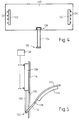
- FIG. 6 shows a modification of the system described above with reference to Figure 1.
- the modified system is viewed in plan from above and only the outboard end of the screening plate 110 A is shown as the modification to the plate affects only this end portion.
- the reason for the modification can be appreciated by considering the dotted line illustration of the outboard end of the chuck 26 and the outboard bobbin tube 102 thereon.
- the free end of chuck 26 projects outwardly (to the left as viewed in Fig. 6) well beyond the outboard tube 102.
- the portion of the chuck outboard of tube 102 has a thread catching and cutting system generally indicated at 150 and formed, for example, in accordance with US Patent 4477034.
- the thread deflector, serving as the auxiliary screening means, is indicated at 440 A.
- This deflector has been slightly modified in comparison with that shown in Figure 3 in that the leading edge of the deflector approaches the modified plate 110 A very closely, so that the gap l shown in Fig. 3 has virtually disappeared. However, the deflector does not extend leftwards as viewed in Fig. 6 (outboard) beyond the outboard edge of tube 102.
- tail 14A (Fig. 1) to be thrown outboard beyond the outboard end of deflector 440A, and to be caught in catching and cutting means 150.
- plate 110A is provided with an extension 111 which lies beside the outboard end of deflector 440A and screens off the package on the upper chuck 24 from the catching and cutting means 150 on the lower chuck.
- extension 111 which lies beside the outboard end of deflector 440A and screens off the package on the upper chuck 24 from the catching and cutting means 150 on the lower chuck.
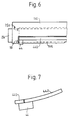
- Fig. 7 shows an additional modification to the combination of the deflector 440 and its carrier 44. If an outgoing (completed) package on the upper chuck has a long projecting tail 14A, then this can be thrown by centrifugal force over the top of the deflector/carrier combination 44, 440 shown in Fig. 3, and can be caught on the friction roll 18. In order to prevent this, a plate 442 is fitted on the carrier 44 to extend away from the deflector bar 440. Plate 442 is viewed in section in Fig. 7 and extends along the full length of the deflector bar 440 thereby providing additional screening between the completed package(s) on the upper chuck and the friction roll 18.
- the invention is not limited to winders of the type described.
- the invention proposes the selective insertion of a screening means between a completed package and a newly forming package in a winder having a plurality of chucks and means enabling transfer of a thread to be wound from one chuck to another.
- Machines of this type are also shown for example in US Patent No. 4298171 where a so-called revolver is used to carry the pair of chucks provided.
- the invention is also not limited to use with friction drives. It is known that the chucks can be driven directly by individual motors - the invention is equally applicable to winders using such drive systems.
Landscapes
- Engineering & Computer Science (AREA)
- Textile Engineering (AREA)
- Replacing, Conveying, And Pick-Finding For Filamentary Materials (AREA)
- Winding Filamentary Materials (AREA)
- Spinning Or Twisting Of Yarns (AREA)
Claims (9)
- Une bobineuse de fil comprenant, un premier mandrin sur lequel des bobines de fil peuvent être enroulées et un deuxième mandrin sur lequel des bobines de fil peuvent être enroulées, un moyen pouvant être actionné pour transférer un fil depuis une bobine enroulée sur le premier mandrin, vers le deuxième mandrin, afin de démarrer l'enroulement d'une bobine sur celui-ci, et un moyen de protection, mobile entre la bobine finie située sur le premier mandrin et la bobine nouvellement en formation située sur le deuxième mandrin, depuis une position rétractée dans une position de fonctionnement,
caractérisée par
un moyen de guidage auxiliaire servant à dévier un fil pendant la commutation de l'enroulement depuis le premier vers le deuxième mandrin, ledit moyen de guidage (44, 440) coopérant avec le moyen de protection (110), afin de protéger une bobine (40) située sur le premier mandrin (24) d'une opération d'enroulement effectuée sur le deuxième mandrin (26). - Une bobineuse selon revendication 1, et comprenant en plus un membre d'entraînement par friction pour entraîner lesdits mandrins en rotation autour de leurs axes de mandrin longitudinaux, ledit moyen de protection pouvant être actionné lorsqu'il se trouve dans sa position de fonctionnement, afin de protéger ladite bobine finie du membre d'entraînement par friction.
- Une bobineuse selon revendication 1,
caractérisée par le fait
qu'un entraînement individuel est prévu pour chaque mandrin. - Une bobineuse selon revendication 1, revendication 2 ou revendication 3,
caractérisée par le fait que
les deux mandrins sont portés par un revolver. - Une bobineuse selon l'une des revendications précédentes,
caractérisée par le fait que
le moyen de protection (110) et le moyen de guidage (44, 440) possèdent chacun une arête, lesdites arêtes étant adjacentes lorsque le moyen de protection (110) et le moyen de guidage (44, 440) sont dans leurs positions de protection. - Une bobineuse selon l'une des revendications précédentes,
caractérisée par
un système de control (138), adapté pour coordonner les mouvements du moyen de protection (110) avec les mouvements des mandrins (24, 26). - Une bobineuse selon revendication 6,
caractérisé par
un système de control (138) réagissant à l'opération de la bobineuse pour rétracter le moyen de protection (110). - Une bobineuse selon l'une des revendications précécentes,
caractérisée par le fait que
le moyen de protection (110) est une plaque incurvée, mobile sur un arc depuis sa position rétractée dans sa position de fonctionnement. - Une bobineuse selon l'une des revendications précédentes,
caractérisée par le fait que
la position rétractée du moyen de protection (110) est adjacente à la position de repos du deuxième mandrin.
Applications Claiming Priority (3)
| Application Number | Priority Date | Filing Date | Title |
|---|---|---|---|
| US06/707,425 US4598876A (en) | 1985-03-01 | 1985-03-01 | Winding machine for filament packages equipped with package screening means |
| EP85114925A EP0192827A3 (fr) | 1985-03-01 | 1985-11-25 | Protection pour bobines de fil |
| US707425 | 2003-12-12 |
Related Parent Applications (2)
| Application Number | Title | Priority Date | Filing Date |
|---|---|---|---|
| EP85114925.2 Division | 1985-11-25 | ||
| EP85114925A Division EP0192827A3 (fr) | 1985-03-01 | 1985-11-25 | Protection pour bobines de fil |
Publications (2)
| Publication Number | Publication Date |
|---|---|
| EP0524657A1 EP0524657A1 (fr) | 1993-01-27 |
| EP0524657B1 true EP0524657B1 (fr) | 1996-09-04 |
Family
ID=24841646
Family Applications (2)
| Application Number | Title | Priority Date | Filing Date |
|---|---|---|---|
| EP85114925A Ceased EP0192827A3 (fr) | 1985-03-01 | 1985-11-25 | Protection pour bobines de fil |
| EP92114175A Expired - Lifetime EP0524657B1 (fr) | 1985-03-01 | 1985-11-25 | Protection pour bobines de fil |
Family Applications Before (1)
| Application Number | Title | Priority Date | Filing Date |
|---|---|---|---|
| EP85114925A Ceased EP0192827A3 (fr) | 1985-03-01 | 1985-11-25 | Protection pour bobines de fil |
Country Status (4)
| Country | Link |
|---|---|
| US (1) | US4598876A (fr) |
| EP (2) | EP0192827A3 (fr) |
| JP (1) | JP2612848B2 (fr) |
| DE (1) | DE3588122T2 (fr) |
Cited By (1)
| Publication number | Priority date | Publication date | Assignee | Title |
|---|---|---|---|---|
| DE102008062161B3 (de) * | 2008-12-13 | 2010-05-06 | Georg Sahm Gmbh & Co. Kg | Spulmaschine mit Trennvorrichtung |
Families Citing this family (12)
| Publication number | Priority date | Publication date | Assignee | Title |
|---|---|---|---|---|
| GB8531151D0 (en) * | 1985-12-18 | 1986-01-29 | Rieter Ag Maschf | Winder layout |
| GB8601453D0 (en) * | 1986-01-22 | 1986-02-26 | Rieter Ag Maschf | Thread guiding & screening elements |
| JP2594554B2 (ja) * | 1987-03-11 | 1997-03-26 | 帝人製機株式会社 | 糸条巻取方法 |
| US5156347A (en) * | 1988-03-30 | 1992-10-20 | Gay Ii Francis V | Automatic continuous fiber winder |
| DE8916288U1 (de) * | 1988-12-22 | 1997-05-22 | Barmag Ag, 42897 Remscheid | Aufspulmaschine |
| JP2553476B2 (ja) * | 1989-05-26 | 1996-11-13 | 村田機械株式会社 | 紡糸巻取機 |
| JP2535536Y2 (ja) * | 1989-07-14 | 1997-05-14 | 村田機械 株式会社 | 紡糸巻取機 |
| GB2248856B (en) * | 1990-10-19 | 1994-08-17 | Rieter Scragg Ltd | Yarn transfer arrangement |
| EP0571318A1 (fr) * | 1992-05-18 | 1993-11-24 | Maschinenfabrik Rieter Ag | Bobinoir |
| BR9204863A (pt) | 1992-11-25 | 1994-03-01 | Johnson & Johnson Ind Com | Absorvente intimo feminino descartavel |
| EP0703179A3 (fr) | 1994-08-24 | 1996-08-21 | Rieter Ag Maschf | Bobinoir automatique et procédé pour le transfert du fil d'une bobine pleine à une bobine vide |
| CN116238967B (zh) * | 2023-05-04 | 2023-07-14 | 东营兆源航空新材料有限公司 | 一种电缆的绕线装置及其使用方法 |
Family Cites Families (12)
| Publication number | Priority date | Publication date | Assignee | Title |
|---|---|---|---|---|
| US3165274A (en) * | 1963-06-20 | 1965-01-12 | Du Pont | Yarn winding apparatus |
| US3409238A (en) * | 1967-03-28 | 1968-11-05 | Du Pont | Continuous yarn windup apparatus |
| CH551924A (fr) * | 1971-05-26 | 1974-07-31 | Maillefer Sa | Dispositif de protection des queues de fil dans un bobinoir a double bobine. |
| CH571451A5 (fr) * | 1973-10-26 | 1976-01-15 | Maillefer Sa | |
| BR7506457A (pt) * | 1974-10-04 | 1976-08-10 | Kobe Steel Ltd | Processo e aparelho para manipular o terminal de um objeto semelhante a fio em um aparelho recolhedor de objeto semelhante a fio |
| US4119278A (en) * | 1977-03-07 | 1978-10-10 | Syncro Machine Company | Continuous long ends wire spooling apparatus |
| GB2105378A (en) * | 1981-09-03 | 1983-03-23 | Rieter Ag Maschf | Thread winding machine |
| DE3274541D1 (en) * | 1981-09-03 | 1987-01-15 | Rieter Ag Maschf | Filament winding machine |
| US4497450A (en) * | 1981-11-10 | 1985-02-05 | Sulzer Brothers Limited | Filament winding machine |
| JPS5957452U (ja) * | 1982-10-12 | 1984-04-14 | 帝人製機株式会社 | 切替巻取機 |
| JPS60145153U (ja) * | 1984-03-02 | 1985-09-26 | 帝人製機株式会社 | 自動切替巻取機 |
| JP2833624B2 (ja) * | 1987-02-27 | 1998-12-09 | 日本化薬株式会社 | 診断試薬用ラテックス |
-
1985
- 1985-03-01 US US06/707,425 patent/US4598876A/en not_active Expired - Fee Related
- 1985-11-25 DE DE3588122T patent/DE3588122T2/de not_active Ceased
- 1985-11-25 EP EP85114925A patent/EP0192827A3/fr not_active Ceased
- 1985-11-25 EP EP92114175A patent/EP0524657B1/fr not_active Expired - Lifetime
-
1986
- 1986-02-19 JP JP61033083A patent/JP2612848B2/ja not_active Expired - Lifetime
Cited By (1)
| Publication number | Priority date | Publication date | Assignee | Title |
|---|---|---|---|---|
| DE102008062161B3 (de) * | 2008-12-13 | 2010-05-06 | Georg Sahm Gmbh & Co. Kg | Spulmaschine mit Trennvorrichtung |
Also Published As
| Publication number | Publication date |
|---|---|
| US4598876A (en) | 1986-07-08 |
| JP2612848B2 (ja) | 1997-05-21 |
| DE3588122T2 (de) | 1997-01-16 |
| EP0192827A2 (fr) | 1986-09-03 |
| EP0192827A3 (fr) | 1987-04-29 |
| JPS61203077A (ja) | 1986-09-08 |
| DE3588122D1 (de) | 1996-10-10 |
| EP0524657A1 (fr) | 1993-01-27 |
Similar Documents
| Publication | Publication Date | Title |
|---|---|---|
| EP0524657B1 (fr) | Protection pour bobines de fil | |
| US4340187A (en) | Bobbin changing apparatus | |
| US5016829A (en) | Takeup machine | |
| US4638955A (en) | Yarn handling apparatus for winding machine | |
| JPS59187631A (ja) | リング精紡機の上方に設けられたボビンクリ−ルからのボビンの抜取りおよびボビンクリ−ルへの装填を行うための装置 | |
| US4598881A (en) | Bobbin inserting device | |
| DE2501735A1 (de) | Verfahren und vorrichtung zur automatisierung des auflaufspulenwechsels an einer spinnmaschine, insbesondere rotor- spinnmaschine | |
| EP0126352B1 (fr) | Disposition de mise en place de support de bobines | |
| US4186890A (en) | Mechanism and method for transferring yarn from a full package to an empty bobbin | |
| US3920193A (en) | Winding apparatus with automatic changing of tubes or the like | |
| US5318232A (en) | Method and apparatus for transferring a thread from a full package to an empty tube | |
| US4709866A (en) | Thread guiding and screening element for use in filament winder | |
| US5431353A (en) | Bobbin winding machine | |
| GB2087936A (en) | Yarn winding apparatus and method | |
| JP2000327228A (ja) | 巻取機の糸掛装置 | |
| GB2179066A (en) | Forming overwrapped thread reserves on bobbins | |
| FI84902C (fi) | Traodupplindningsanordning. | |
| EP0198517B2 (fr) | Dispositif de mise en place de support de bobines | |
| EP0329202B1 (fr) | Dispositif de mise en place de support de bobines | |
| US4693430A (en) | Winding station of an automatic winding machine | |
| EP0330245A2 (fr) | Dispositif de mise en place de supports de bobines | |
| CS246964B1 (en) | Apparatus for returning of the yarn | |
| GB2179376A (en) | Bobbin inserting device | |
| JPH0741735Y2 (ja) | 分かれ巻検出装置 | |
| GB2179064A (en) | Bobbin doffing device |
Legal Events
| Date | Code | Title | Description |
|---|---|---|---|
| PUAI | Public reference made under article 153(3) epc to a published international application that has entered the european phase |
Free format text: ORIGINAL CODE: 0009012 |
|
| AC | Divisional application: reference to earlier application |
Ref document number: 192827 Country of ref document: EP |
|
| AK | Designated contracting states |
Kind code of ref document: A1 Designated state(s): CH DE FR GB IT LI |
|
| 17P | Request for examination filed |
Effective date: 19930809 |
|
| 17Q | First examination report despatched |
Effective date: 19950706 |
|
| GRAG | Despatch of communication of intention to grant |
Free format text: ORIGINAL CODE: EPIDOS AGRA |
|
| GRAH | Despatch of communication of intention to grant a patent |
Free format text: ORIGINAL CODE: EPIDOS IGRA |
|
| GRAH | Despatch of communication of intention to grant a patent |
Free format text: ORIGINAL CODE: EPIDOS IGRA |
|
| GRAA | (expected) grant |
Free format text: ORIGINAL CODE: 0009210 |
|
| AC | Divisional application: reference to earlier application |
Ref document number: 192827 Country of ref document: EP |
|
| AK | Designated contracting states |
Kind code of ref document: B1 Designated state(s): CH DE FR GB IT LI |
|
| PG25 | Lapsed in a contracting state [announced via postgrant information from national office to epo] |
Ref country code: FR Effective date: 19960904 |
|
| REF | Corresponds to: |
Ref document number: 3588122 Country of ref document: DE Date of ref document: 19961010 |
|
| ITF | It: translation for a ep patent filed | ||
| PG25 | Lapsed in a contracting state [announced via postgrant information from national office to epo] |
Ref country code: GB Effective date: 19961204 |
|
| EN | Fr: translation not filed | ||
| PLBE | No opposition filed within time limit |
Free format text: ORIGINAL CODE: 0009261 |
|
| GBPC | Gb: european patent ceased through non-payment of renewal fee |
Effective date: 19961204 |
|
| 26N | No opposition filed | ||
| PGFP | Annual fee paid to national office [announced via postgrant information from national office to epo] |
Ref country code: DE Payment date: 20041117 Year of fee payment: 20 |
|
| PGFP | Annual fee paid to national office [announced via postgrant information from national office to epo] |
Ref country code: CH Payment date: 20041119 Year of fee payment: 20 |
|
| REG | Reference to a national code |
Ref country code: CH Ref legal event code: PL |
|
| PG25 | Lapsed in a contracting state [announced via postgrant information from national office to epo] |
Ref country code: DE Free format text: THE PATENT HAS BEEN ANNULLED BY A DECISION OF A NATIONAL AUTHORITY Effective date: 20100223 |