EP0525229A1 - Kolben, insbesondere zum Herausdrücken von flüssigem Metall aus einem Giesszylinder - Google Patents
Kolben, insbesondere zum Herausdrücken von flüssigem Metall aus einem Giesszylinder Download PDFInfo
- Publication number
- EP0525229A1 EP0525229A1 EP91112740A EP91112740A EP0525229A1 EP 0525229 A1 EP0525229 A1 EP 0525229A1 EP 91112740 A EP91112740 A EP 91112740A EP 91112740 A EP91112740 A EP 91112740A EP 0525229 A1 EP0525229 A1 EP 0525229A1
- Authority
- EP
- European Patent Office
- Prior art keywords
- cap
- carrier
- piston
- sealing ring
- face
- Prior art date
- Legal status (The legal status is an assumption and is not a legal conclusion. Google has not performed a legal analysis and makes no representation as to the accuracy of the status listed.)
- Granted
Links
- 229910001338 liquidmetal Inorganic materials 0.000 title claims abstract description 8
- 239000007788 liquid Substances 0.000 claims abstract description 8
- 238000005266 casting Methods 0.000 claims abstract description 5
- 229910001369 Brass Inorganic materials 0.000 claims abstract description 4
- 229910052782 aluminium Inorganic materials 0.000 claims abstract description 4
- XAGFODPZIPBFFR-UHFFFAOYSA-N aluminium Chemical compound [Al] XAGFODPZIPBFFR-UHFFFAOYSA-N 0.000 claims abstract description 4
- 239000010951 brass Substances 0.000 claims abstract description 4
- 238000004512 die casting Methods 0.000 claims abstract description 4
- 238000007789 sealing Methods 0.000 claims description 31
- 230000002093 peripheral effect Effects 0.000 claims description 9
- 230000037431 insertion Effects 0.000 claims description 2
- 238000003780 insertion Methods 0.000 claims description 2
- 239000004411 aluminium Substances 0.000 abstract 1
- 238000001816 cooling Methods 0.000 description 3
- 239000002826 coolant Substances 0.000 description 2
- 230000014759 maintenance of location Effects 0.000 description 2
- 229910052751 metal Inorganic materials 0.000 description 2
- 239000002184 metal Substances 0.000 description 2
- 230000000694 effects Effects 0.000 description 1
Images


Classifications
-
- B—PERFORMING OPERATIONS; TRANSPORTING
- B22—CASTING; POWDER METALLURGY
- B22D—CASTING OF METALS; CASTING OF OTHER SUBSTANCES BY THE SAME PROCESSES OR DEVICES
- B22D17/00—Pressure die casting or injection die casting, i.e. casting in which the metal is forced into a mould under high pressure
- B22D17/20—Accessories: Details
- B22D17/2015—Means for forcing the molten metal into the die
- B22D17/203—Injection pistons
-
- Y—GENERAL TAGGING OF NEW TECHNOLOGICAL DEVELOPMENTS; GENERAL TAGGING OF CROSS-SECTIONAL TECHNOLOGIES SPANNING OVER SEVERAL SECTIONS OF THE IPC; TECHNICAL SUBJECTS COVERED BY FORMER USPC CROSS-REFERENCE ART COLLECTIONS [XRACs] AND DIGESTS
- Y10—TECHNICAL SUBJECTS COVERED BY FORMER USPC
- Y10T—TECHNICAL SUBJECTS COVERED BY FORMER US CLASSIFICATION
- Y10T403/00—Joints and connections
- Y10T403/70—Interfitted members
- Y10T403/7005—Lugged member, rotary engagement
- Y10T403/7007—Bayonet joint
Definitions
- the invention relates to a piston, in particular for pushing out liquid metal - preferably liquid aluminum or liquid brass - from a casting cylinder of a die casting press, with a cap to be placed on a carrier and fastened to the carrier in such a way that the cap has an inner top surface of an end face faces the wearer.
- Such a piston is known from EP-A2-423 413.
- the cap with an internal thread is to be thermally screwed onto an external thread of the carrier.
- the object of the invention is to facilitate the fitting and fastening of the cap to the carrier in order to enable the cap to be replaced quickly, so that the corresponding downtimes of the machine in which the piston works are reduced.
- the piston is characterized in that there are recesses in the inner peripheral surface of the cap in the vicinity of its free edge surface for receiving bayonet catch projections on the circumference of the carrier.
- the piston is preferably characterized in that there are four equally spaced bayonet locking projections on the carrier, which four insertion recesses in the cap are assigned.
- the piston is preferably characterized in that the axial dimensions of the recesses receiving the bayonet lock projections are axial Allowing movement play between the inner cover surface of the cap and the end face of the wearer, somewhat larger - preferably 0.1 to 0.2 mm larger - than the axial dimensions of the bayonet catch projections.
- the piston is preferably characterized in that for fixing the cap to the carrier the cap has at least one round recess in its free edge for receiving a head part of a screw to be screwed into the carrier .
- the cap is preferably provided with a sealing ring in the front area of its circumference, as is known in principle from EP-A2-423 413.
- a sealing ring in the front area of its circumference, as is known in principle from EP-A2-423 413.
- the sealing ring not only encompasses an outer circumferential web on the cap with an inner circumferential groove, but that moreover, the sealing ring in front of the circumferential groove has a cylindrical inner circumferential surface which surrounds two axially successive, cylindrical outer circumferential surface sections of the cap at a distance, the front cylindrical outer circumferential surface having a larger diameter than the rear cylindrical outer circumferential surface.
- the rear cylindrical outer peripheral surface is designed as a retention puncture for solidified liquid metal. Metal solidified in the recessed groove spreads the sealing ring apart and thus increases its sealing effect.
- the sealing ring is held on the cap by the circumferential web.
- the front boundary surface of the circumferential web forms a stop surface for the sealing ring, thus absorbs a pressure acting axially on the sealing ring and delimits a sealing zone to the sealing ring.
- the cap preferably has a ring surface pointing forward at a small distance from a rear end face of the sealing ring.
- the cap In order to also utilize liquid metal which penetrates axially over the outer circumferential surface of the sealing ring, the cap preferably has a section of reduced outer diameter behind the sealing ring which forms a storage zone. If metal enters this storage zone, the user recognizes that the sealing ring no longer has to be completely sealed and replaced.
- the piston according to the exemplary embodiment has a cap 4 to be secured to a carrier 2 and serves as the actual piston.
- the cap 4 faces an end face 8 of the carrier 2 with an inner top face 6.
- the inner circumferential surface 10 of the cap 4 is in the vicinity of its free edge surface 12 four depressions 14, which have the same angular spacing from one another, for receiving four bayonet catches 16 on the circumference 18 of the carrier 2.
- the axial dimensions of the depressions 14 receiving the bayonet catch protrusions 16 1 and 2 an axial play of play between the inner cover surface 6 of the cap 4 and the end face 8 of the carrier 2, which permits temperature expansion of the cap 4 and which is apparent from FIGS. 1 and 2, is somewhat larger than the axial dimensions of the bayonet lock projections 16.
- the cap 4 has in its free edge surface 12 a round recess 20 for receiving a head part 22 of a screw 24 to be screwed into the carrier 2.
- the carrier 2 is provided with an internal thread 26 for screwing onto an external thread of a piston rod, not shown.
- an internal thread 26 for screwing onto an external thread of a piston rod, not shown.
- attachment surfaces 28 for a U key on the outside of the carrier are provided.
- the piston rod and the carrier 2 are axially penetrated by a tube 30 which ends in a bore 32 in front of the end face 8 of the carrier 2.
- a coolant can be pressed through the tube 30 into a radial cannula 34 in the end face 8 of the carrier, which coolant can then be drawn through axial recesses 36 in a front annular support surface 38 of the carrier via an annular channel 40 and obliquely running bores 42 in a carrier 2 formed in the carrier 2.
- the tube enclosing the annular space 44 and from there flows back through the carrier 2. Details of this type of cooling are described in EP-A2-423 413.
- a sealing ring 46 is shown schematically, which encloses the front end of the cap 4.
- cap and sealing ring which can also be used independently of the cap 4 which can be plugged onto the carrier 2 by means of a bayonet lock and which is explained in connection with FIGS. 1 to 5, is shown in FIG. 6.
- FIG. 6 shows a cap 50 which has a cylindrical extension 102 with an outer ring web 104 on an outer cover surface 100. This annular web 104 engages in an inner annular groove 106 of a sealing ring 108.
- the cylindrical extension 102 is provided with an annular recess 103 which serves to receive an inner annular web 109 of the sealing ring 108.
- the sealing ring 108 and the shoulder 102 have at the front first parallel, then diverging towards the front, opposing boundary surfaces 128, 130.
- the rear boundary surface 140 of the sealing ring 108 merges into the outer peripheral surface 142 of the sealing ring 108 via a run-up slope 136.
- the sealing ring 108 In front of the annular groove 106, the sealing ring 108 has a cylindrical inner circumferential surface which forms a section of the boundary surface 128 and surrounds two axially successive cylindrical outer circumferential sections 112, 114 of the cap 50, the front cylindrical outer circumferential section 114 having a larger diameter than the rear cylindrical Outer circumferential section 112.
- the outer circumferential section 112 thus delimits the retention puncture described at the beginning.
- the cap 50 has a section 118 of reduced outer diameter which forms the storage zone 116 described at the outset.
- the direction of flow of the liquid metal into the spaces between the sealing ring 108 and the cap 50 and in the axial direction over the outer peripheral surface 142 of the sealing ring 108 is indicated by arrows A and B.
- an inner peripheral surface 120 of a casting cylinder is indicated, within which the piston is to be displaced.
Landscapes
- Engineering & Computer Science (AREA)
- Mechanical Engineering (AREA)
- Pistons, Piston Rings, And Cylinders (AREA)
- Injection Moulding Of Plastics Or The Like (AREA)
- Sealing Devices (AREA)
- Details Of Reciprocating Pumps (AREA)
Abstract
Description
- Die Erfindung betrifft einen Kolben, insbesondere zum Herausdrücken von flüssigem Metall - vorzugsweise flüssigem Aluminium oder flüssigem Messing - aus einem Gießzylinder einer Druckgußpresse, mit einer auf einen Träger aufzusetzenden und an dem Träger derart zu befestigenden Kappe, daß die Kappe mit einer inneren Deckfläche einer Stirnfläche des Trägers gegenübersteht.
- Ein solcher Kolben ist nach der EP-A2-423 413 bekannt. Dort ist die Kappe mit einem Innengewinde thermisch auf ein Außengewinde des Trägers aufzuschrauben.
- Aufgabe der Erfindung ist es, das Aufsetzen und Befestigen der Kappe an dem Träger zu erleichtern, um ein rasches Auswechseln der Kappe zu ermöglichen, so daß die entsprechenden Stillstandszeiten der Maschine, in der der Kolben arbeitet, verringert werden.
- Zur Lösung dieser Aufgabe ist der Kolben dadurch gekennzeichnet, daß sich in der Innenumfangsfläche der Kappe in der Nähe ihrer freien Randfläche Vertiefungen zur Aufnahme von Bajonettverschluß-Vorsprüngen am Umfang des Trägers befinden.
- Um die Kappe nach nur 1/8 Drehung in bezug zum Träger von dem Träger lösen zu können oder an dem Träger befestigen zu können, ist der Kolben bevorzugt dadurch gekennzeichnet, daß sich an dem Träger vier gleiche Winkelabstände voneinander aufweisende Bajonettverschluß-Vorsprünge befinden, denen vier Einsteck-Ausnehmungen in der Kappe zugeordnet sind.
- Um eine Art Pumpkühlung der Kappe zu erhalten, wobei ein Kühlkreislauf vorgesehen sein kann, wie er in der EP-A2-423 413 beschrieben ist, ist der Kolben bevorzugt dadurch gekennzeichnet, daß die axialen Abmessungen der die Bajonettverschluß-Vorsprünge aufnehmenden Vertiefungen, ein axiales Bewegungsspiel zwischen der inneren Deckfläche der Kappe und der Stirnfläche des Trägers gestattend, etwas größer - vorzugsweise um 0,1 bis 0,2 mm größer - als die axialen Abmessungen der Bajonettverschluß-Vorsprünge sind.
- Um die Kappe an dem Träger in einfacher Weise sichern zu können, ist der Kolben bevorzugt dadurch gekennzeichnet, daß zur Festlegung der Kappe an dem Träger die Kappe in ihrem freien Rand wenigstens eine runde Ausnehmung zur Aufnahme eines Kopfteils einer in den Träger zu schraubenden Schraube aufweist.
- Die Kappe ist im vorderen Bereich seines Umfangs bevorzugt mit einem Dichtungsring versehen, wie dies grundsätzlich nach der EP-A2-423 413 bekannt ist. Besonders bewährt hat sich in Zusammenwirken mit der erfindungsgemäßen Kappe, aber auch bei anderen Kappen, wie sie in der EP-A2-423 413 beispielsweise beschrieben sind, daß der Dichtungsring nicht nur mit einer inneren Umfangsnut einen äußeren Umfangssteg an der Kappe umgreift, sondern daß überdies der Dichtungsring vor der Umfangsnut eine zylindrische Innenumfangsfläche aufweist, die zwei axial aufeinander folgende, zylindrische Außenumfangsflächenabschnitte der Kappe mit Abstand umschließt, wobei die vordere zylindrische Außenumfangsfläche einen größeren Durchmesser hat als die hintere zylindrische Außenumfangsfläche.
- Die hintere zylindrische Außenumfangsfläche ist dabei als ein Rückhalteeinstich für erstarrtes flüssiges Metall ausgebildet. In dem Rückhalteeinstich erstarrtes Metall spreizt den Dichtungsring auseinander und erhöht somit seine Dichtwirkung.
- Der Dichtungsring wird durch den Umfangssteg an der Kappe festgehalten. Die vordere Begrenzungsfläche des Umfangsstegs bildet dabei eine Anschlagfläche für den Dichtungsring, nimmt also einen axial auf den Dichtungsring wirkenden Druck auf und begrenzt eine Dichtzone zum Dichtungsring. Dementsprechend weist die Kappe bevorzugt in geringem Abstand von einer hinteren Stirnfläche des Dichtungsrings eine nach vorne weisende Ringfläche auf.
- Um auch axial über die Außenumfangsfläche des Dichtungsrings dringendes flüssiges Metall zur Dichtung auszunutzen, weist bevorzugt die Kappe hinter dem Dichtungsring einen eine Speicherzone bildenden Abschnitt verringerten Außendurchmessers auf. Tritt in diese Speicherzone Metall ein, so erkennt der Benutzer, daß der Dichtungsring nicht mehr vollständig abdichtet und ausgewechselt werden muß.
- Die Erfindung wird im folgenden an Ausführungsbeispielen unter Hinweis auf die beigefügten Zeichnungen erläutert.
-
- Fig. 1 zeigt im Achsschnitt teilweise in Seitenansicht eine auf einem Träger befindliche Kappe, wobei der Träger relativ zur Kappe nach vorne geschoben ist.
- Fig. 2 zeigt entsprechend Fig. 1 den Fall, daß der Träger relativ zur Kappe nach hinten gezogen ist.
- Fig. 3 zeigt einen Schnitt längs 111-111 in Fig. 1 bei noch nicht verriegelter Kappe.
- Fig. 4 zeigt entsprechend Fig. 3 die verriegelte Kappe.
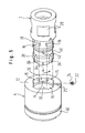
- Fig. 5 zeigt eine Explosionsdarstellung von Kappe und Träger.
- Fig. 6 zeigt in Seitenansicht teilweise weggebrochen den vorderen Bereich einer Kappe mit zugehörigem Dichtungsring.
- Der Kolben nach dem Ausführungsbeispiel weist eine an einen Träger 2 zu sichernde, als eigentlicher Kolben dienende Kappe 4 auf. Die Kappe 4 steht mit einer inneren Deckfläche 6 einer Stirnfläche 8 des Trägers 2 gegenüber. In der Innenumfangsfläche 10 der Kappe 4 befinden sich in der Nähe ihrer freien Randfläche 12 vier Vertiefungen 14, die gleiche Winkelabstände voneinander haben, zur Aufnahme von entsprechend vier Bajonettverschlüssen 16 am Umfang 18 des Trägers 2. Die axialen Abmessungen der die Bajonettverschluß-Vorsprünge 16 aufnehmenden Vertiefungen 14 sind - ein aus Fig. 1 und 2 ersichtliches axiales, Temperaturdehnungen der Kappe 4 zulassendes Bewegungsspiel zwischen der inneren Deckfläche 6 der Kappe 4 und der Stirnfläche 8 des Trägers 2 gestattend - etwas größer als die axialen Abmessungen der Bajonettverschluß-Vorsprünge 16.
- Zur Festlegung der Kappe 4 an dem Träger 2 weist die Kappe 4 in ihrer freien Randfläche 12 eine runde Ausnehmung 20 zur Aufnahme eines Kopfteils 22 einer in den Träger 2 zu schraubenden Schraube 24 auf.
- Der Träger 2 ist mit einem Innengewinde 26 zum Aufschrauben auf ein Außengewinde einer nicht dargestellten Kolbenstange versehen. Zum Zwecke des Aufschraubens befinden sich auf der Außenseite des Trägers Ansatzflächen 28 für einen U-Schlüssel.
- Die Kolbenstange und der Träger 2 sind axial von einem Rohr 30 durchsetzt, das in einer Bohrung 32 vor der Stirnfläche 8 des Trägers 2 endet. Durch das Rohr 30 kann ein Kühlmittel in eine Radialkanüle 34 in der Stirnfläche 8 des Trägers gedrückt werden, das dann durch axiale Ausnehmungen 36 in einer vorderen ringförmigen Stützfläche 38 des Trägers über einen Ringkanal 40 und schräg verlaufende Bohrungen 42 in einen im Träger 2 ausgebildeten, das Rohr umschließenden Ringraum 44 und von dort durch den Träger 2 wieder zurückströmt. Einzelheiten dieser Art von Kühlung sind in der EP-A2-423 413 beschrieben.
- In den Fig. 1, 2 und 5 ist schematisch ein Dichtungsring 46 dargestellt, der das vordere Ende der Kappe 4 umschließt.
- Eine besonders bevorzugte Ausführungsform von Kappe und Dichtungsring, die auch unabhängig von der in Zusammenhang mit Fig. 1 bis 5 erläuterten, durch einen Bajonettverschluß auf den Träger 2 aufsteckbaren Kappe 4 verwendet werden kann, ist in Fig. 6 dargestellt.
- Fig. 6 zeigt eine Kappe 50, die auf einer äußeren Deckfläche 100 einen zylindrischen Ansatz 102 mit einem äußeren Ringsteg 104 aufweist. Dieser Ringsteg 104 greift in eine innere Ringnut 106 eines Dichtungsrings 108 ein. Der zylindrische Ansatz 102 ist mit einer Ringausnehmung 103 versehen, die der Aufnahme eines inneren Ringstegs 109 des Dichtungsrings 108 dient.
- Der Dichtungsring 108 und der Ansatz 102 weisen frontseitig zunächst parallele, dann nach vorne auseinanderstrebende, einander gegenüberstehende Begrenzungsflächen 128, 130 auf. Einer durch den Ansatz 102 radial begrenzten Ringschulter 132 der äußeren Deckfläche 100 der Kappe 50 steht mit geringem Abstand eine rückwärtige Begrenzungsfläche 140 des Dichtungsrings 108 gegenüber. Die rückwärtige Begrenzungsfläche 140 des Dichtungsrings 108 geht in die äußere Umfangsfläche 142 des Dichtungsrings 108 über eine Auflaufschräge 136 über.
- Vor der Ringnut 106 weist der Dichtungsring 108 eine zylindrische Innenumfangsfläche auf, die einen Abschnitt der Begrenzungsfläche 128 bildet und zwei axial aufeinanderfolgende zylindrische Außenumfangsabschnitte 112, 114 der Kappe 50 mit Abstand umschließt, wobei der vordere zylindrische Außenumfangsabschnitt 114 einen größeren Durchmesser hat als der hintere zylindrische Außenumfangsabschnitt 112. Der Außenumfangsabschnitt 112 begrenzt somit den eingangs beschriebenen Rückhalte-Einstich.
- Hinter dem Dichtungsring 108 weist die Kappe 50 einen die eingangs beschriebene Speicherzone 116 bildenden Abschnitt 118 verringerten Außendurchmessers auf.
- Die Strömungsrichtung des flüssigen Metalls in die Räume zwischen dem Dichtungsring 108 und der Kappe 50 und in Axialrichtung über die äußere Umfangsfläche 142 des Dichtungsrings 108 ist durch Pfeile A und B angedeutet. Außerdem ist eine Innenumfangsfläche 120 eines Gießzylinders angedeutet, innerhalb dem der Kolben zu verschieben ist.
Claims (7)
Priority Applications (5)
| Application Number | Priority Date | Filing Date | Title |
|---|---|---|---|
| DE59108332T DE59108332D1 (de) | 1991-07-29 | 1991-07-29 | Kolben, insbesondere zum Herausdrücken von flüssigem Metall aus einem Giesszylinder |
| ES91112740T ES2095886T3 (es) | 1991-07-29 | 1991-07-29 | Embolo, particularmente para empujar metal liquido fuera de un cilindro de colada. |
| EP91112740A EP0525229B1 (de) | 1991-07-29 | 1991-07-29 | Kolben, insbesondere zum Herausdrücken von flüssigem Metall aus einem Giesszylinder |
| US07/919,258 US5233912A (en) | 1991-07-29 | 1992-07-27 | Piston for forcing liquid metal out of a casting cylinder |
| JP22189892A JP3300045B2 (ja) | 1991-07-29 | 1992-07-28 | ピストン及びピストン用シールリング |
Applications Claiming Priority (1)
| Application Number | Priority Date | Filing Date | Title |
|---|---|---|---|
| EP91112740A EP0525229B1 (de) | 1991-07-29 | 1991-07-29 | Kolben, insbesondere zum Herausdrücken von flüssigem Metall aus einem Giesszylinder |
Publications (2)
| Publication Number | Publication Date |
|---|---|
| EP0525229A1 true EP0525229A1 (de) | 1993-02-03 |
| EP0525229B1 EP0525229B1 (de) | 1996-11-06 |
Family
ID=8206992
Family Applications (1)
| Application Number | Title | Priority Date | Filing Date |
|---|---|---|---|
| EP91112740A Expired - Lifetime EP0525229B1 (de) | 1991-07-29 | 1991-07-29 | Kolben, insbesondere zum Herausdrücken von flüssigem Metall aus einem Giesszylinder |
Country Status (5)
| Country | Link |
|---|---|
| US (1) | US5233912A (de) |
| EP (1) | EP0525229B1 (de) |
| JP (1) | JP3300045B2 (de) |
| DE (1) | DE59108332D1 (de) |
| ES (1) | ES2095886T3 (de) |
Cited By (5)
| Publication number | Priority date | Publication date | Assignee | Title |
|---|---|---|---|---|
| DE4230080A1 (de) * | 1992-09-09 | 1994-03-10 | Hugo Kunz | Druckgießkolben, insbesondere für Kaltkammer-Druckgießmaschinen |
| US5680894A (en) * | 1996-10-23 | 1997-10-28 | Lindberg Corporation | Apparatus for the injection molding of a metal alloy: sub-ring concept |
| WO2004110679A1 (de) * | 2003-06-13 | 2004-12-23 | Allper Ag | Kolben für einekaltkammer-druckgiessmaschine |
| DE202010008596U1 (de) | 2010-09-21 | 2010-12-02 | Schmelzmetall (Deutschland) Gmbh | Druckgusskolben |
| EP2554296A2 (de) | 2011-08-05 | 2013-02-06 | Schmelzmetall AG | Druckgusskolbenkopf |
Families Citing this family (27)
| Publication number | Priority date | Publication date | Assignee | Title |
|---|---|---|---|---|
| EP0525229B1 (de) | 1991-07-29 | 1996-11-06 | Allper Ag | Kolben, insbesondere zum Herausdrücken von flüssigem Metall aus einem Giesszylinder |
| US5411350A (en) * | 1993-11-03 | 1995-05-02 | Loctite Corporation | Quick connect/disconnect device, and dispensing apparatus comprising same |
| JP3019713B2 (ja) * | 1994-02-21 | 2000-03-13 | 豊田合成株式会社 | 操作ノブの組付け構造 |
| US5653322A (en) * | 1996-01-30 | 1997-08-05 | Borg-Warner Automotive, Inc. | Two piece clutch assembly having twist lock joint |
| US5607251A (en) * | 1996-04-03 | 1997-03-04 | The Stanley Works | Quick coupler assembly for hanging attachment |
| US5687604A (en) * | 1996-05-30 | 1997-11-18 | Exco Technologies Ltd. | Thermal controlled mandrel with replaceable tip for copper and brass extrusion |
| US5913605A (en) * | 1997-09-17 | 1999-06-22 | G. H. Hensley Industries, Inc. | Rotary lock system for wear runner assembly |
| DE19923341B4 (de) * | 1999-05-21 | 2005-03-03 | Audi Ag | Verfahren zum Betreiben einer Druckgießmaschine sowie Druckgießmaschine zur Durchführung des Verfahrens |
| DE10037887A1 (de) * | 2000-08-03 | 2002-02-14 | Mahle Gmbh | Kolben-Zylinder-Baueinheit für einen Verbrennungsmotor mit einem schaftlosen Kolben |
| US6598450B2 (en) | 2001-11-02 | 2003-07-29 | Sequa Can Machinery, Inc. | Internally cooled punch |
| EP1483074B1 (de) * | 2002-03-04 | 2007-06-13 | Allper Ag | Dichtring und kolben für einen druckgiesszylinder |
| US8550743B2 (en) * | 2005-09-30 | 2013-10-08 | Medtronic, Inc. | Sliding lock device |
| DE102005048717A1 (de) * | 2005-10-12 | 2007-04-19 | Allper Ag | Mehrteiliger Kolben für eine Kaltkammer-Giessmaschine |
| ITBS20060087A1 (it) * | 2006-04-12 | 2007-10-13 | Copromec S R L | Pistone per macchine per la pressofusione a camera fredda |
| US8048069B2 (en) | 2006-09-29 | 2011-11-01 | Medtronic, Inc. | User interface for ablation therapy |
| US20080286398A1 (en) * | 2007-05-15 | 2008-11-20 | Jui-Hsiang Wang | Fast-to-install structure for a threaded rod of an injection molding machine |
| IT1393330B1 (it) | 2009-01-21 | 2012-04-20 | Brondolin S P A | Pistoni per pressofusione |
| IT1393329B1 (it) | 2009-01-21 | 2012-04-20 | Brondolin S P A | Pistone e anello di tenuta per pressofusione |
| DE102009056903A1 (de) * | 2009-12-03 | 2011-06-09 | Danfoss A/S | Hydraulische Kolbenmaschine, insbesondere wasserhydraulische Maschine |
| FR2974023A1 (fr) * | 2011-04-14 | 2012-10-19 | Sidel Participations | Dispositif d'assemblage d'un outillage sur un support |
| MX350918B (es) * | 2012-04-20 | 2017-09-25 | Cpr Suisse S A | Pistón para máquinas de fundición a presión de cámara fría. |
| ES2449165B1 (es) * | 2014-02-21 | 2014-09-02 | Alrotec Tecnology S.L.U. | Pistón para máquinas de inyección de cámara fría |
| WO2018119517A1 (en) * | 2016-12-30 | 2018-07-05 | Exco Technologies Limited | Die-casting piston, and die-casting apparatus incorporating same |
| US10807286B2 (en) | 2017-04-06 | 2020-10-20 | Mold-Masters (2007) Limited | Liquid injection molding apparatus |
| DE102017003693B3 (de) * | 2017-04-15 | 2018-06-14 | Wieland-Werke Ag | Druckgießkolben |
| US10987731B1 (en) * | 2020-07-30 | 2021-04-27 | Exco Technologies Limited | Die-casting piston, and die-casting apparatus incorporating same |
| ES2915404B2 (es) * | 2020-12-21 | 2023-01-05 | Univ La Laguna | Embolo medidor de presion para plataformas de impresion 3d en extrusion de masas semisolidas |
Citations (3)
| Publication number | Priority date | Publication date | Assignee | Title |
|---|---|---|---|---|
| DE8304487U1 (de) * | 1983-02-18 | 1985-05-02 | Glas, Friedrich, 8192 Geretsried | Kolben für Druckgießmaschinen |
| DE9014033U1 (de) * | 1990-10-09 | 1990-12-13 | D. Schade GmbH, 2356 Aukrug | Kolben für Druckgießmaschinen |
| EP0423413B1 (de) * | 1989-10-18 | 1997-04-02 | Allper Ag | Kolben, insbesondere für eine Druckgusspresse |
Family Cites Families (12)
| Publication number | Priority date | Publication date | Assignee | Title |
|---|---|---|---|---|
| US2862738A (en) * | 1954-10-27 | 1958-12-02 | Charles A D Bayley | Subaqueous structures for supporting a working platform above water |
| US2844424A (en) * | 1956-02-20 | 1958-07-22 | Rand Goetze Corp | Piston sealing means |
| US2844422A (en) * | 1956-12-05 | 1958-07-22 | Rand Goetze Corp | Piston ring |
| DE1029615B (de) * | 1957-02-14 | 1958-05-08 | Krauss Maffei Ag | Kolbenring |
| US2901258A (en) * | 1957-09-30 | 1959-08-25 | Brandafi Gabriel | Drill press spindle |
| DE2446503A1 (de) * | 1974-09-28 | 1976-04-15 | Hugo Kunz | Druckkolben fuer eine druckgiessmaschine |
| SE7510628L (sv) * | 1974-09-28 | 1976-03-29 | Hugo Kunz | Tryckkolv for en tryckgjutmaskin |
| US4529330A (en) * | 1983-06-30 | 1985-07-16 | Otis Engineering Corporation | Cylinder connection |
| DE3934778A1 (de) * | 1988-12-28 | 1990-07-05 | Allper Ag | Kolben, insbesondere fuer eine druckgusspresse |
| US5094148A (en) * | 1989-05-08 | 1992-03-10 | Habley Medical Technology Corporation | Piston stem insert for a carpule based piston |
| DE9014003U1 (de) * | 1990-10-08 | 1990-12-13 | Alfred Kunz GmbH & Co, 8000 München | Kontaktaufnahmeprofil, insbesondere für geschirmte Türen mit Türrahmen für abgeschirmte Räume |
| EP0525229B1 (de) | 1991-07-29 | 1996-11-06 | Allper Ag | Kolben, insbesondere zum Herausdrücken von flüssigem Metall aus einem Giesszylinder |
-
1991
- 1991-07-29 EP EP91112740A patent/EP0525229B1/de not_active Expired - Lifetime
- 1991-07-29 DE DE59108332T patent/DE59108332D1/de not_active Expired - Fee Related
- 1991-07-29 ES ES91112740T patent/ES2095886T3/es not_active Expired - Lifetime
-
1992
- 1992-07-27 US US07/919,258 patent/US5233912A/en not_active Expired - Lifetime
- 1992-07-28 JP JP22189892A patent/JP3300045B2/ja not_active Expired - Fee Related
Patent Citations (3)
| Publication number | Priority date | Publication date | Assignee | Title |
|---|---|---|---|---|
| DE8304487U1 (de) * | 1983-02-18 | 1985-05-02 | Glas, Friedrich, 8192 Geretsried | Kolben für Druckgießmaschinen |
| EP0423413B1 (de) * | 1989-10-18 | 1997-04-02 | Allper Ag | Kolben, insbesondere für eine Druckgusspresse |
| DE9014033U1 (de) * | 1990-10-09 | 1990-12-13 | D. Schade GmbH, 2356 Aukrug | Kolben für Druckgießmaschinen |
Cited By (8)
| Publication number | Priority date | Publication date | Assignee | Title |
|---|---|---|---|---|
| DE4230080A1 (de) * | 1992-09-09 | 1994-03-10 | Hugo Kunz | Druckgießkolben, insbesondere für Kaltkammer-Druckgießmaschinen |
| DE4230080C2 (de) * | 1992-09-09 | 1998-04-09 | Hugo Kunz | Druckgießkolben, insbesondere für Kaltkammer-Druckgießmaschinen |
| US5680894A (en) * | 1996-10-23 | 1997-10-28 | Lindberg Corporation | Apparatus for the injection molding of a metal alloy: sub-ring concept |
| WO2004110679A1 (de) * | 2003-06-13 | 2004-12-23 | Allper Ag | Kolben für einekaltkammer-druckgiessmaschine |
| DE202010008596U1 (de) | 2010-09-21 | 2010-12-02 | Schmelzmetall (Deutschland) Gmbh | Druckgusskolben |
| EP2431112A1 (de) | 2010-09-21 | 2012-03-21 | Schmelzmetall AG | Druckgusskolben |
| EP2554296A2 (de) | 2011-08-05 | 2013-02-06 | Schmelzmetall AG | Druckgusskolbenkopf |
| DE102011052446A1 (de) | 2011-08-05 | 2013-02-07 | Schmelzmetall Ag | Druckgusskolbenkopf |
Also Published As
| Publication number | Publication date |
|---|---|
| ES2095886T3 (es) | 1997-03-01 |
| DE59108332D1 (de) | 1996-12-12 |
| JPH0617931A (ja) | 1994-01-25 |
| JP3300045B2 (ja) | 2002-07-08 |
| US5233912A (en) | 1993-08-10 |
| EP0525229B1 (de) | 1996-11-06 |
Similar Documents
| Publication | Publication Date | Title |
|---|---|---|
| EP0525229B1 (de) | Kolben, insbesondere zum Herausdrücken von flüssigem Metall aus einem Giesszylinder | |
| EP0423413A2 (de) | Kolben, insbesondere für eine Druckgusspresse | |
| DE3345959C2 (de) | Zylinderkopfbefestigungskonstruktion | |
| DE2337648C2 (de) | Kaltkammer-Druckgießmaschine | |
| WO2003074211A2 (de) | Kolben für eine kaltkammer-druckgiessmaschine | |
| DE1955586A1 (de) | Fluessigkeitsgekuehlte ein- oder mehrzylindrige Zweitaktbrennkraftmaschine | |
| DE1097210B (de) | Kolben fuer Brennkraftmaschinen | |
| EP1660769B1 (de) | Mehrteiliger kolben f r einen verbrennungsmotor | |
| EP1635973B1 (de) | Kolben für eine kaltkammer-druckgiessmaschine | |
| DE4441735A1 (de) | Druckgießkolben, insbesondere für Kaltkammer-Druckgießmaschinen | |
| DE19847865C2 (de) | Zylinderlaufbuchse | |
| DE1207152B (de) | Fluessigkeitsgekuehlter Kolben geschmiedeter oder gepresster Ausfuehrung fuer Brennkraftmaschinen | |
| DE873185C (de) | Kolben, insbesondere fuer Brennkraftmaschinen | |
| DE2242947A1 (de) | Einrichtung zur kuehlung von thermisch hochbeanspruchten stellen an verbrennungskraftmaschinen | |
| EP0901852B1 (de) | Kolben für eine Warmkammer-Druckgiessmachine | |
| DE4302157A1 (de) | Füllkammer für eine Druckgießmaschine | |
| DE2904883B1 (de) | Druckkolben fuer Druckgiessmaschinen | |
| DE2431654A1 (de) | Arbeitszylinder fuer pneumatische und hydraulische medien | |
| DE948020C (de) | Kreuzkopfbrennkraftmaschine | |
| EP0117913A2 (de) | Mehrteiliger flüssigkeitsgekühlter Kolben für Verbrennungsmotoren | |
| DE1915726C (de) | Zerlegbarer Zylinder fur Hubkolben maschinen | |
| DE585877C (de) | Vorrichtung zur Befestigung der Kolbenstange am Kreuzkopf von Kolbenkraftmaschinen | |
| DE1939435A1 (de) | Muldenkolben fuer Brennkraftmaschinen | |
| DE29516807U1 (de) | Handrad oder Handkurbel zur Befestigung auf einer Welle | |
| DE3421762A1 (de) | Kolbenstangenfuehrung fuer hydraulik-zylinder |
Legal Events
| Date | Code | Title | Description |
|---|---|---|---|
| PUAI | Public reference made under article 153(3) epc to a published international application that has entered the european phase |
Free format text: ORIGINAL CODE: 0009012 |
|
| AK | Designated contracting states |
Kind code of ref document: A1 Designated state(s): DE ES FR GB IT |
|
| 17P | Request for examination filed |
Effective date: 19930629 |
|
| 17Q | First examination report despatched |
Effective date: 19941125 |
|
| GRAG | Despatch of communication of intention to grant |
Free format text: ORIGINAL CODE: EPIDOS AGRA |
|
| GRAH | Despatch of communication of intention to grant a patent |
Free format text: ORIGINAL CODE: EPIDOS IGRA |
|
| GRAH | Despatch of communication of intention to grant a patent |
Free format text: ORIGINAL CODE: EPIDOS IGRA |
|
| GRAA | (expected) grant |
Free format text: ORIGINAL CODE: 0009210 |
|
| AK | Designated contracting states |
Kind code of ref document: B1 Designated state(s): DE ES FR GB IT |
|
| ITF | It: translation for a ep patent filed | ||
| GBT | Gb: translation of ep patent filed (gb section 77(6)(a)/1977) |
Effective date: 19961108 |
|
| REF | Corresponds to: |
Ref document number: 59108332 Country of ref document: DE Date of ref document: 19961212 |
|
| ET | Fr: translation filed | ||
| REG | Reference to a national code |
Ref country code: ES Ref legal event code: FG2A Ref document number: 2095886 Country of ref document: ES Kind code of ref document: T3 |
|
| PLBE | No opposition filed within time limit |
Free format text: ORIGINAL CODE: 0009261 |
|
| STAA | Information on the status of an ep patent application or granted ep patent |
Free format text: STATUS: NO OPPOSITION FILED WITHIN TIME LIMIT |
|
| 26N | No opposition filed | ||
| REG | Reference to a national code |
Ref country code: GB Ref legal event code: IF02 |
|
| PGFP | Annual fee paid to national office [announced via postgrant information from national office to epo] |
Ref country code: ES Payment date: 20080729 Year of fee payment: 18 Ref country code: DE Payment date: 20080415 Year of fee payment: 18 |
|
| PGFP | Annual fee paid to national office [announced via postgrant information from national office to epo] |
Ref country code: IT Payment date: 20080725 Year of fee payment: 18 |
|
| PGFP | Annual fee paid to national office [announced via postgrant information from national office to epo] |
Ref country code: GB Payment date: 20080722 Year of fee payment: 18 |
|
| GBPC | Gb: european patent ceased through non-payment of renewal fee |
Effective date: 20090729 |
|
| REG | Reference to a national code |
Ref country code: FR Ref legal event code: ST Effective date: 20100331 |
|
| PG25 | Lapsed in a contracting state [announced via postgrant information from national office to epo] |
Ref country code: FR Free format text: LAPSE BECAUSE OF NON-PAYMENT OF DUE FEES Effective date: 20090731 |
|
| PGFP | Annual fee paid to national office [announced via postgrant information from national office to epo] |
Ref country code: FR Payment date: 20080425 Year of fee payment: 18 |
|
| PG25 | Lapsed in a contracting state [announced via postgrant information from national office to epo] |
Ref country code: GB Free format text: LAPSE BECAUSE OF NON-PAYMENT OF DUE FEES Effective date: 20090729 |
|
| PG25 | Lapsed in a contracting state [announced via postgrant information from national office to epo] |
Ref country code: DE Free format text: LAPSE BECAUSE OF NON-PAYMENT OF DUE FEES Effective date: 20100202 |
|
| REG | Reference to a national code |
Ref country code: ES Ref legal event code: FD2A Effective date: 20090730 |
|
| PG25 | Lapsed in a contracting state [announced via postgrant information from national office to epo] |
Ref country code: ES Free format text: LAPSE BECAUSE OF NON-PAYMENT OF DUE FEES Effective date: 20090730 |
|
| PG25 | Lapsed in a contracting state [announced via postgrant information from national office to epo] |
Ref country code: IT Free format text: LAPSE BECAUSE OF NON-PAYMENT OF DUE FEES Effective date: 20090729 |