EP0527705A1 - Method and apparatus for detecting warp tension in a weaving loom - Google Patents
Method and apparatus for detecting warp tension in a weaving loom Download PDFInfo
- Publication number
- EP0527705A1 EP0527705A1 EP92810597A EP92810597A EP0527705A1 EP 0527705 A1 EP0527705 A1 EP 0527705A1 EP 92810597 A EP92810597 A EP 92810597A EP 92810597 A EP92810597 A EP 92810597A EP 0527705 A1 EP0527705 A1 EP 0527705A1
- Authority
- EP
- European Patent Office
- Prior art keywords
- tension
- warp
- detecting
- roller
- supported
- Prior art date
- Legal status (The legal status is an assumption and is not a legal conclusion. Google has not performed a legal analysis and makes no representation as to the accuracy of the status listed.)
- Withdrawn
Links
Images

Classifications
-
- G—PHYSICS
- G01—MEASURING; TESTING
- G01L—MEASURING FORCE, STRESS, TORQUE, WORK, MECHANICAL POWER, MECHANICAL EFFICIENCY, OR FLUID PRESSURE
- G01L5/00—Apparatus for, or methods of, measuring force, work, mechanical power, or torque, specially adapted for specific purposes
- G01L5/04—Apparatus for, or methods of, measuring force, work, mechanical power, or torque, specially adapted for specific purposes for measuring tension in flexible members, e.g. ropes, cables, wires, threads, belts or bands
- G01L5/10—Apparatus for, or methods of, measuring force, work, mechanical power, or torque, specially adapted for specific purposes for measuring tension in flexible members, e.g. ropes, cables, wires, threads, belts or bands using electrical means
- G01L5/106—Apparatus for, or methods of, measuring force, work, mechanical power, or torque, specially adapted for specific purposes for measuring tension in flexible members, e.g. ropes, cables, wires, threads, belts or bands using electrical means for measuring a reaction force applied on a cantilever beam
-
- D—TEXTILES; PAPER
- D03—WEAVING
- D03D—WOVEN FABRICS; METHODS OF WEAVING; LOOMS
- D03D49/00—Details or constructional features not specially adapted for looms of a particular type
- D03D49/04—Control of the tension in warp or cloth
- D03D49/18—Devices for indicating warp tension
-
- G—PHYSICS
- G01—MEASURING; TESTING
- G01L—MEASURING FORCE, STRESS, TORQUE, WORK, MECHANICAL POWER, MECHANICAL EFFICIENCY, OR FLUID PRESSURE
- G01L5/00—Apparatus for, or methods of, measuring force, work, mechanical power, or torque, specially adapted for specific purposes
- G01L5/04—Apparatus for, or methods of, measuring force, work, mechanical power, or torque, specially adapted for specific purposes for measuring tension in flexible members, e.g. ropes, cables, wires, threads, belts or bands
- G01L5/10—Apparatus for, or methods of, measuring force, work, mechanical power, or torque, specially adapted for specific purposes for measuring tension in flexible members, e.g. ropes, cables, wires, threads, belts or bands using electrical means
-
- G—PHYSICS
- G01—MEASURING; TESTING
- G01L—MEASURING FORCE, STRESS, TORQUE, WORK, MECHANICAL POWER, MECHANICAL EFFICIENCY, OR FLUID PRESSURE
- G01L5/00—Apparatus for, or methods of, measuring force, work, mechanical power, or torque, specially adapted for specific purposes
- G01L5/04—Apparatus for, or methods of, measuring force, work, mechanical power, or torque, specially adapted for specific purposes for measuring tension in flexible members, e.g. ropes, cables, wires, threads, belts or bands
- G01L5/10—Apparatus for, or methods of, measuring force, work, mechanical power, or torque, specially adapted for specific purposes for measuring tension in flexible members, e.g. ropes, cables, wires, threads, belts or bands using electrical means
- G01L5/108—Apparatus for, or methods of, measuring force, work, mechanical power, or torque, specially adapted for specific purposes for measuring tension in flexible members, e.g. ropes, cables, wires, threads, belts or bands using electrical means for measuring a reaction force applied on a single support, e.g. a glider
Definitions
- the present invention relates to a method and an apparatus of detecting warp tension in a weaving loom having a roller adapted to receive the tension of warp yarns for detection thereof while guiding such warp yarns.
- a warp tension detecting apparatus of the above type is disclosed by Publication of Japanese Patent Application No. 1-266241 (1989).
- This prior art apparatus includes a tension detecting roller having its opposite ends supported by a pair of tension levers which are in turn supported by detecting levers.
- a load cell is interposed between one detecting lever and a stationary portion of a loom frame so that the warp tension is transmitted from the roller to the load cell through the tension lever and the detecting lever.
- the paired detecting levers are interconnected by a single support shaft rotatably mounted between opposite side frames of the loom and each detecting lever is fixedly connected to its corresponding end of the support shaft. In such an arrangement, the whole warp tension exerted on the tension roller is transmitted to the load cell and such warp tension is detected by the load cell.
- the support shaft interconnecting the paired detecting levers tends to have flexural oscillation under the influence of vibration which is typical of loom operation and such flexural oscillation badly affects the durability of the support shaft.
- the support shaft should be rigid enough to resist the flexural oscillation. Though the shaft should be made larger in diameter for a loom having an increased weaving width, such enlargement of the shaft for rigidity improvement inevitably invites an increase in the shaft weight and hence in its manufacturing cost.
- a warp tension detecting roller supported at its opposite ends by respective tension detecting arms which are in turn supported by separate support shafts.
- partial warp tension transmitted to either one of the arms is detected and the whole warp tension is calculated on the basis of the detected partial warp tension.
- each of the shafts can be made short enough to be free from flexural oscillation and, therefore, there will be no need for rigidity improvement for a loom with an increased weaving width.
- the tension detecting arms are urged to rotate about the support shafts by the tension of warp yarns, their rotation is stopped by any suitable tension receiving members located between the respective tension detecting arms and stationary portions of the loom.
- Either one of the tension receiving members includes a pressure responsive member, e.g. a load cell, for detecting partial warp tension which is transmitted to the corresponding arm.
- the other partial warp tension is carried by the opposite tension detecting arm and it can be calculated on the basis of the warp tension distribution along the weaving width and the above detected warp tension.
- the tension of the whole warp yarns is the sum of the detected tension and the calculated tension.
- Reference numeral 1 designates a warp beam driven to rotate by a motor 21.
- a sheet of warp yarns T unwound from the warp beam 1 is guided by a back roller 2 and then a tension detecting roller 3 in contact therewith.
- the back roller 2 is supported between lateral side frames (not shown) of a loom in a rotatable but not displaceable manner.
- Back brackets 4, 5 are stationarily disposed adjacent the respective opposite ends of the back roller 2 and rotatably support a pair of shafts 6, 7 in a cantilever manner.
- the shafts 6. 7 have tension detecting arms 10, 11 clamped thereto by bolts 8, 9.
- the tension detecting arms 10, 11 have at one ends thereof pins 14, 15 which support easing levers 12, 13 depending therefrom.
- the tension detecting roller 3 is rotatably supported at its opposite ends by the easing levers 12, 13 at their center portions.
- the easing levers 12, 13 are operatively connected to a crank mechanism (not shown) of the loom by way of easing rods 16, 17, respectively, so that the levers 12, 13 are swung back and forth about the pins 14, 15 in response to the warp tension change taking place periodically for each complete turn of the loom.
- Such swinging motion of the easing levers 12, 13 causes the tension detecting roller 3 to swing about the pins 14, 15 in synchronism with the periodic change in the warp tension thereby to absorb such tension change.
- a load cell 19 is interposed between one tension detecting arm 10 and a stationary portion of the loom, while a rod 18 is located between the other tension detecting arm 11 and a stationary portion of the loom.
- the tension To of the whole warp yarns received by the tension detecting roller 3 is distributed to the opposite easing levers 12, 13 and received ultimately by the load cell 19 and the rod 18 by way of the tension detecting arms 10, 11, respectively, and the rotation of the arms 10, 11 about the shafts 6, 7 is prevented by the load cell 19 and the rod 18. That is, the load cell 19 is adapted to detect a partial warp tension T1 transmitted thereto through the tension detecting arm 10.
- T1 T0 (L2+L3/2)/L
- T2 T0 (L1+L3/2)/L (2)
- T0 represents the tension of all warp yarns
- L the distance between the rod 18 and the load cell 19
- L1 the distance between the load cell 19 and its adjacent lateral end t1 of the warp sheet T
- L2 the distance between the rod 18 and its adjacent lateral end t2 of the warp sheet T
- L3 the distance between t1 and t2.
- T2/T1 (L1+L3/2)/(L2+L3/2) (3)
- the data of tension T1 detected by the load cell 19 is transmitted to a computer control C which in turn calculates the tension T2 on the basis of the detected tension T1 and the equation (3).
- the tension T12 of all warp yarns is the sum of the tension T1 and the tension T2. Comparing the tension T12 with the desired target warp tension T0, the data of which tension T12 is previously inputted to the control C through an input device 20, the control C is operated to control the rotational speed of the motor 21 in such a way that the tension T12 coincides with the target tension T0.
- the shafts 6, 7 supporting the tension detecting arms 10, 11 are provided separately, they are free from harmful flexural oscillation which is otherwise produced by the vibration typical of the loom operation.
- the separate support shafts 6, 7 only have to be long enough just to support the tension detecting arms 10, 11 and their rigidity does not have to be increased for a loom with a greater weaving width.
- the warp tension detecting apparatus of the invention can improve its durability while reducing the weight and manufacturing cost of the support members for the tension detecting arms 10, 11.
- the apparatus of the invention requires no space for installation of a shaft between the tension detecting arms 10, 11, thus providing sufficient room for installing other component parts of the loom.
- the tension T12 of all warp yarns can be monitored by detecting the tension T1 applied to the load cell 19 through only one tension detecting arm 10. Therefore, the use of only a single load cell 19 can serve for the purpose of warp tension controlling.
- the present invention is not limited to the above embodiment, but it may be practiced in other modified forms, as exemplified in FIG. 3.
- the warp tensions T1 and T2 received by the tension detecting arms 10, 11 are detected by two load cells 19, 22 and the tension T12 of all warp yarns is calculated by adding the detected tensions T1 and T2.
- the warp tension is received by two rods through the tension detecting arms 10, 11 and the tension is detected by detecting the strains produced in the arms 10, 11 by use of any suitable strain detectors.
- It is an object of the invention is to provide a warp tension detecting apparatus having a good durability.
- the warp yarn sheet T unwound from the warp beam 1 is fed while being guided by the back roller 2 and then the warp tension detecting roller 3.
- the warp tension detecting roller 3 is supported at its opposite ends by easing levers 12, 13 which are in turn supported depending therefrom by means of pins 14, 15.
- the warp tension detecting arms 10, 11 are supported independently and rotatably by the back brackets by way of the separate support shafts 6, 7, respectively.
- the rotation of the warp tension detecting arm 10 about the shaft 6 is stopped by the load cell 19 and the rotation of the other arm 11 about the shaft 7 is stopped by the rod 18.
Landscapes
- Physics & Mathematics (AREA)
- General Physics & Mathematics (AREA)
- Engineering & Computer Science (AREA)
- Textile Engineering (AREA)
- Looms (AREA)
Abstract
It is an object of the invention is to provide a warp tension detecting apparatus having a good durability. The warp yarn sheet (T) unwound from the warp beam (1) is fed while being guided by the back roller (2) and then the warp tension detecting roller (3). The warp tension detecting roller (3) is supported at its opposite ends by easing levers (12, 13) which are in turn supported depending therefrom by means of pins (14, 15). The warp tension detecting arms (10, 11) are supported independently and rotatably by the back brackets by way of the separate support shafts (6, 7), respectively. The rotation of the warp tension detecting arm (10) about the shaft (6) is stopped by the load cell (19) and the rotation of the other arm (11) about the shaft (7) is stopped by the rod (18).
Description
- The present invention relates to a method and an apparatus of detecting warp tension in a weaving loom having a roller adapted to receive the tension of warp yarns for detection thereof while guiding such warp yarns.
- A warp tension detecting apparatus of the above type is disclosed by Publication of Japanese Patent Application No. 1-266241 (1989). This prior art apparatus includes a tension detecting roller having its opposite ends supported by a pair of tension levers which are in turn supported by detecting levers. A load cell is interposed between one detecting lever and a stationary portion of a loom frame so that the warp tension is transmitted from the roller to the load cell through the tension lever and the detecting lever. The paired detecting levers are interconnected by a single support shaft rotatably mounted between opposite side frames of the loom and each detecting lever is fixedly connected to its corresponding end of the support shaft. In such an arrangement, the whole warp tension exerted on the tension roller is transmitted to the load cell and such warp tension is detected by the load cell.
- However, the support shaft interconnecting the paired detecting levers tends to have flexural oscillation under the influence of vibration which is typical of loom operation and such flexural oscillation badly affects the durability of the support shaft. The support shaft should be rigid enough to resist the flexural oscillation. Though the shaft should be made larger in diameter for a loom having an increased weaving width, such enlargement of the shaft for rigidity improvement inevitably invites an increase in the shaft weight and hence in its manufacturing cost.
- It is an object of the present invention, therefore, to provide a warp tension detecting apparatus that can solve the above problems successfully.
- According to the invention, there is provided a warp tension detecting roller supported at its opposite ends by respective tension detecting arms which are in turn supported by separate support shafts.
- Also according to the invention, partial warp tension transmitted to either one of the arms is detected and the whole warp tension is calculated on the basis of the detected partial warp tension.
- Because the paired tension detecting arms are supported by separate shafts, each of the shafts can be made short enough to be free from flexural oscillation and, therefore, there will be no need for rigidity improvement for a loom with an increased weaving width.
- Though the tension detecting arms are urged to rotate about the support shafts by the tension of warp yarns, their rotation is stopped by any suitable tension receiving members located between the respective tension detecting arms and stationary portions of the loom. Either one of the tension receiving members includes a pressure responsive member, e.g. a load cell, for detecting partial warp tension which is transmitted to the corresponding arm. The other partial warp tension is carried by the opposite tension detecting arm and it can be calculated on the basis of the warp tension distribution along the weaving width and the above detected warp tension. The tension of the whole warp yarns is the sum of the detected tension and the calculated tension.
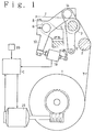
- The following will describe an embodiment of the warp tension detecting apparatus of the present invention with reference to FIGS. 1 and 2.
- FIG. 1
- is a side view partially in section showing the embodiment of warp yarn tension detecting apparatus of the present invention.
- FIG. 2
- is a perspective view showing the embodiment.
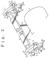
- FIG. 3
- is a perspective view showing another embodiment of the apparatus according to the present invention.
-
Reference numeral 1 designates a warp beam driven to rotate by amotor 21. A sheet of warp yarns T unwound from thewarp beam 1 is guided by aback roller 2 and then atension detecting roller 3 in contact therewith. Theback roller 2 is supported between lateral side frames (not shown) of a loom in a rotatable but not displaceable manner. -
Back brackets back roller 2 and rotatably support a pair ofshafts shafts 6. 7 havetension detecting arms bolts tension detecting arms pins tension detecting roller 3 is rotatably supported at its opposite ends by theeasing levers - The
easing levers rods levers pins tension detecting roller 3 to swing about thepins - A
load cell 19 is interposed between onetension detecting arm 10 and a stationary portion of the loom, while arod 18 is located between the othertension detecting arm 11 and a stationary portion of the loom. The tension To of the whole warp yarns received by thetension detecting roller 3 is distributed to theopposite easing levers load cell 19 and therod 18 by way of thetension detecting arms arms shafts load cell 19 and therod 18. That is, theload cell 19 is adapted to detect a partial warp tension T1 transmitted thereto through thetension detecting arm 10. - The partial tension T₁ transmitted through the detecting
arm 10 and a partial tension T₂ transmitted to therod 18 through the detectingarm 11 can be expressed by the following equations (1) and (2), respectively.


where, T₀ represents the tension of all warp yarns, L the distance between therod 18 and theload cell 19, L₁ the distance between theload cell 19 and its adjacent lateral end t₁ of the warp sheet T, L₂ the distance between therod 18 and its adjacent lateral end t₂ of the warp sheet T, and L₃ the distance between t₁ and t₂. - The equation (3) below can be introduced from the equations (1) and (2).

The data of tension T₁ detected by theload cell 19 is transmitted to a computer control C which in turn calculates the tension T₂ on the basis of the detected tension T₁ and the equation (3). The tension T₁₂ of all warp yarns is the sum of the tension T₁ and the tension T₂. Comparing the tension T₁₂ with the desired target warp tension T₀, the data of which tension T₁₂ is previously inputted to the control C through aninput device 20, the control C is operated to control the rotational speed of themotor 21 in such a way that the tension T₁₂ coincides with the target tension T₀. - As it is now apparent from the foregoing, because the
shafts tension detecting arms separate support shafts tension detecting arms tension detecting arms tension detecting arms - Additionally, according to the above-described embodiment, the tension T₁₂ of all warp yarns can be monitored by detecting the tension T₁ applied to the
load cell 19 through only onetension detecting arm 10. Therefore, the use of only asingle load cell 19 can serve for the purpose of warp tension controlling. - It is to be noted that the present invention is not limited to the above embodiment, but it may be practiced in other modified forms, as exemplified in FIG. 3. In this modification, the warp tensions T₁ and T₂ received by the
tension detecting arms load cells tension detecting arms arms - According to the above-described invention, wherein there is provided a warp tension detecting roller supported at its opposite ends by respective tension detecting arms which are in turn supported by separate support shafts, flexural oscillation can be eliminated and the increased rigidity and hence increased weight and manufacturing cost can be avoided.
- According to the invention, wherein partial warp tension transmitted to either one of the arms is detected and the tension of the whole warp yarns is calculated on the basis of the detected partial warp tension, it can offer an advantage, in addition to the first embodiment of the invention, where the use of a single warp tension detector does well serve for the purpose of controlling the warp yarn tension as conventionally practiced.
- It is an object of the invention is to provide a warp tension detecting apparatus having a good durability. The warp yarn sheet T unwound from the
warp beam 1 is fed while being guided by theback roller 2 and then the warptension detecting roller 3. The warptension detecting roller 3 is supported at its opposite ends by easinglevers pins tension detecting arms separate support shafts tension detecting arm 10 about theshaft 6 is stopped by theload cell 19 and the rotation of theother arm 11 about theshaft 7 is stopped by therod 18. - 3.... Tension detecting roller; 6, 7.... Support shafts; 10, 11 .... Tension detecting arms; 19.... Load cell; T .... Warp yarn sheet.
Claims (8)
- Apparatus for detecting warp tension in a weaving loom having a roller (3) for detecting the tension of warp yarns (T) being let off from a warp beam (1) while guiding such warp yarns (T), said tension detecting roller (3) being supported at its opposite ends by respective tension detecting arms (10, 11) and said detecting arms (10, 11) being supported by separate shafts (5, 6).
- Apparatus for detecting warp tension in a weaving loom having a roller (3) for detecting the tension of warp yarns (T) being let off from a warp beam (1) while guiding such warp yarns (T), said tension detecting roller (3) being supported at one of its opposite ends by a tension detecting arm (10), said tension detecting arm (10) being supported by a separate shaft (6).
- Apparatus as claimed in claim 2, said detecting roller (3) being supported on each of its opposite ends by a tension detecting arm (10, 11), said tension detecting arms (10, 11) being supported by separate shafts (6, 5).
- Apparatus as claimed in claim 2 or claim 3, further including easing lever means (12, 13, 16, 17) pivotally conntected (14, 15) to said tension detecting arm/s (10, 11) and the roller (3) being mount on the easing levers (12, 13), said easing levers (12, 13) being periodically moved forth and back by easing lever drive means (12, 13) in response to the change of the warp tension, thereby causing the tension detecting roller (3) to swing in synchronism with the periodic change in the warp tension, as to absorb/compensate such change in warp tension.
- Apparatus as claimed in any of claims 1 to 4, further including at least one load measuring cell (19, 22) connected to a tension detecting arm (10, 11) and for measuring tension of at least part of the tension load (T₁, T₂) exercised onto the detecting roller (3) by at least part of warp threads of the warp sheet (T).
- Apparatus as claimed in any of claims 1 to 5, further including computer means (C) for calculating the warp tension (T₁, T₂, T₁₂) of part or all of the warp threads of the warp sheet (T)
- Method for detecting warp tension in a warp tension detecting apparatus in a weaving loom having a roller (3) for detecting the tension of warp yarns (T) being let off from a warp beam (1) while guiding such warp yarns (T), said tension detecting roller (3) being supported at its opposite ends by respective tension detecting arms (10, 11) and said detecting arms (10, 11) being supported by separate shafts (14, 15) so that the whole warp tension received by said roller (3) is complementarily distributed to said arms (10, 11), wherein partial warp tension distributed to either one of said arms (10, 11) is detected (19) and the whole warp tension is calculated (C) on the basis of said detected partial warp tension.
- Loom with an apparatus for detecting warp tension as per any of claims 1 to 6.
Applications Claiming Priority (2)
| Application Number | Priority Date | Filing Date | Title |
|---|---|---|---|
| JP20163391A JPH0551845A (en) | 1991-08-12 | 1991-08-12 | Method for detecting warp tension in weaving machine and device therefor |
| JP201633/91 | 1991-08-12 |
Publications (1)
| Publication Number | Publication Date |
|---|---|
| EP0527705A1 true EP0527705A1 (en) | 1993-02-17 |
Family
ID=16444314
Family Applications (1)
| Application Number | Title | Priority Date | Filing Date |
|---|---|---|---|
| EP92810597A Withdrawn EP0527705A1 (en) | 1991-08-12 | 1992-08-05 | Method and apparatus for detecting warp tension in a weaving loom |
Country Status (2)
| Country | Link |
|---|---|
| EP (1) | EP0527705A1 (en) |
| JP (1) | JPH0551845A (en) |
Cited By (14)
| Publication number | Priority date | Publication date | Assignee | Title |
|---|---|---|---|---|
| US5437314A (en) * | 1993-05-11 | 1995-08-01 | Tsudakoma Kogyo Kabushiki Kaisha | Warp feed controller having tension detectors for use in twin beam weaving machine |
| BE1008135A3 (en) * | 1994-03-18 | 1996-01-23 | Picanol Nv | Device and method for setting warp tension |
| CH688048A5 (en) * | 1994-03-18 | 1997-04-30 | Fms Force Measuring Systems Ag | Loom back rest withstanding vibrations |
| EP0789097A1 (en) * | 1996-02-05 | 1997-08-13 | Sulzer RàTi Ag | Method and apparatus for measuring warp tension in a weaving loom |
| EP1445363A3 (en) * | 2003-02-04 | 2005-01-12 | Promatech S.p.A. | Improved arrangement of a back rest for a weaving loom |
| EP1544338A3 (en) * | 2003-02-19 | 2006-04-05 | Kabushiki Kaisha Toyota Jidoshokki | Warp tension detecting device for loom |
| EP1878821A1 (en) * | 2006-07-11 | 2008-01-16 | Tsudakoma Kogyo Kabushiki Kaisha | Roll supporting device of loom |
| EP2184390A1 (en) * | 2008-11-10 | 2010-05-12 | Tsudakoma Kogyo Kabushiki Kaisha | Let-off device of loom using positive easing mechanism |
| CN102080298A (en) * | 2010-11-23 | 2011-06-01 | 东华大学 | Segment-based method for detecting and controlling yarn tension of weaving machine on line |
| CN102505291A (en) * | 2011-10-11 | 2012-06-20 | 扬州新扬科技发展产业有限公司 | Control device of warp-sending tension of carbon fiber weaving machine |
| CN102817161A (en) * | 2012-09-03 | 2012-12-12 | 南通纺织职业技术学院 | Sample loom used for test weaving of leno weave |
| CN103061011A (en) * | 2011-10-19 | 2013-04-24 | 津田驹工业株式会社 | Tension detection apparatus for loom |
| CN103898668A (en) * | 2014-03-24 | 2014-07-02 | 青岛天一集团红旗纺织机械有限公司 | Let-off device of air jet loom |
| CN112697330A (en) * | 2020-12-16 | 2021-04-23 | 安徽博润纺织品有限公司 | Production process of high-tension polyester screen |
Families Citing this family (3)
| Publication number | Priority date | Publication date | Assignee | Title |
|---|---|---|---|---|
| JPH0967739A (en) * | 1995-08-24 | 1997-03-11 | Urase:Kk | Warp feeding device |
| CN103526438A (en) * | 2013-10-28 | 2014-01-22 | 吴江唯奇布业有限公司 | Warp loosening device of weaving machine |
| CN110629365B (en) * | 2019-09-26 | 2024-09-13 | 青岛天一红旗纺机集团有限公司 | Stable control device for raising of flannelette loom |
Citations (4)
| Publication number | Priority date | Publication date | Assignee | Title |
|---|---|---|---|---|
| FR1288658A (en) * | 1961-05-08 | 1962-03-24 | Sulzer Ag | Loom and method of operating the loom |
| US4561580A (en) * | 1984-08-22 | 1985-12-31 | Celanese Corporation | Apparatus for measuring the tension in an endless elongate member |
| FR2577575A1 (en) * | 1985-02-14 | 1986-08-22 | Saurer Ag Adolph | WEAPON DEVICE FOR WEAVING. |
| GB2179164A (en) * | 1985-07-26 | 1987-02-25 | Polygraph Leipzig | Web transport and tension-measuring apparatus |
-
1991
- 1991-08-12 JP JP20163391A patent/JPH0551845A/en active Pending
-
1992
- 1992-08-05 EP EP92810597A patent/EP0527705A1/en not_active Withdrawn
Patent Citations (4)
| Publication number | Priority date | Publication date | Assignee | Title |
|---|---|---|---|---|
| FR1288658A (en) * | 1961-05-08 | 1962-03-24 | Sulzer Ag | Loom and method of operating the loom |
| US4561580A (en) * | 1984-08-22 | 1985-12-31 | Celanese Corporation | Apparatus for measuring the tension in an endless elongate member |
| FR2577575A1 (en) * | 1985-02-14 | 1986-08-22 | Saurer Ag Adolph | WEAPON DEVICE FOR WEAVING. |
| GB2179164A (en) * | 1985-07-26 | 1987-02-25 | Polygraph Leipzig | Web transport and tension-measuring apparatus |
Cited By (22)
| Publication number | Priority date | Publication date | Assignee | Title |
|---|---|---|---|---|
| US5437314A (en) * | 1993-05-11 | 1995-08-01 | Tsudakoma Kogyo Kabushiki Kaisha | Warp feed controller having tension detectors for use in twin beam weaving machine |
| BE1008135A3 (en) * | 1994-03-18 | 1996-01-23 | Picanol Nv | Device and method for setting warp tension |
| CH688048A5 (en) * | 1994-03-18 | 1997-04-30 | Fms Force Measuring Systems Ag | Loom back rest withstanding vibrations |
| EP0789097A1 (en) * | 1996-02-05 | 1997-08-13 | Sulzer RàTi Ag | Method and apparatus for measuring warp tension in a weaving loom |
| US5827975A (en) * | 1996-02-05 | 1998-10-27 | Sulzer Rueti Ag | Method and apparatus for measuring the tension of the warp in a weaving machine |
| EP1445363A3 (en) * | 2003-02-04 | 2005-01-12 | Promatech S.p.A. | Improved arrangement of a back rest for a weaving loom |
| EP1544338A3 (en) * | 2003-02-19 | 2006-04-05 | Kabushiki Kaisha Toyota Jidoshokki | Warp tension detecting device for loom |
| CN1306088C (en) * | 2003-02-19 | 2007-03-21 | 株式会社丰田自动织机 | Warp yarn tension detecting mechanism for loom |
| EP1878821A1 (en) * | 2006-07-11 | 2008-01-16 | Tsudakoma Kogyo Kabushiki Kaisha | Roll supporting device of loom |
| CN101104976B (en) * | 2006-07-11 | 2012-05-30 | 津田驹工业株式会社 | Roll supporting device of loom |
| CN101736497B (en) * | 2008-11-10 | 2014-02-19 | 津田驹工业株式会社 | Warp let-off device for looms with positive warp loosening mechanism |
| EP2184390A1 (en) * | 2008-11-10 | 2010-05-12 | Tsudakoma Kogyo Kabushiki Kaisha | Let-off device of loom using positive easing mechanism |
| CN102080298A (en) * | 2010-11-23 | 2011-06-01 | 东华大学 | Segment-based method for detecting and controlling yarn tension of weaving machine on line |
| CN102505291B (en) * | 2011-10-11 | 2013-06-12 | 扬州新扬科技发展产业有限公司 | Control device of warp-sending tension of carbon fiber weaving machine |
| CN102505291A (en) * | 2011-10-11 | 2012-06-20 | 扬州新扬科技发展产业有限公司 | Control device of warp-sending tension of carbon fiber weaving machine |
| CN103061011A (en) * | 2011-10-19 | 2013-04-24 | 津田驹工业株式会社 | Tension detection apparatus for loom |
| EP2584079A3 (en) * | 2011-10-19 | 2013-11-13 | Tsudakoma Kogyo Kabushiki Kaisha | Tension detection apparatus for loom |
| CN103061011B (en) * | 2011-10-19 | 2015-05-27 | 津田驹工业株式会社 | Tension detection apparatus for loom |
| CN102817161A (en) * | 2012-09-03 | 2012-12-12 | 南通纺织职业技术学院 | Sample loom used for test weaving of leno weave |
| CN103898668A (en) * | 2014-03-24 | 2014-07-02 | 青岛天一集团红旗纺织机械有限公司 | Let-off device of air jet loom |
| CN103898668B (en) * | 2014-03-24 | 2015-07-08 | 青岛天一集团红旗纺织机械有限公司 | Let-off device of air jet loom |
| CN112697330A (en) * | 2020-12-16 | 2021-04-23 | 安徽博润纺织品有限公司 | Production process of high-tension polyester screen |
Also Published As
| Publication number | Publication date |
|---|---|
| JPH0551845A (en) | 1993-03-02 |
Similar Documents
| Publication | Publication Date | Title |
|---|---|---|
| EP0527705A1 (en) | Method and apparatus for detecting warp tension in a weaving loom | |
| KR870001701B1 (en) | Web guiding and decurling apparatus | |
| US4262706A (en) | Loom | |
| US4477006A (en) | Offset pivot guiding assembly | |
| US5090453A (en) | Torsion bar type warp tensioning device for a loom | |
| US4546801A (en) | Warp let-off control device for weaving machines | |
| US4534386A (en) | Tensioning beam assembly for a weaving machine | |
| US4572244A (en) | Warp let-off motion for loom having two warp beams | |
| EP1544338A2 (en) | Warp tension detecting device for loom | |
| EP0537111A1 (en) | Apparatus for detecting warp tension in a loom | |
| US20030019970A1 (en) | Winding machine | |
| JP2534202Y2 (en) | Warp tension detecting device in loom | |
| GB2151666A (en) | Winder for cross-wound bobbins: traverse support | |
| CZ204193A3 (en) | Device for automatic control of warp yarn tension stress | |
| CN1114694A (en) | Improved device for measuring the warp yarn tension in a loom | |
| EP0372575B1 (en) | Encoder installing structure | |
| US4754784A (en) | Loom having a supporting and adjusting device for warp yarn guidance | |
| JP3374450B2 (en) | Warp tension detecting device in loom | |
| JP2983473B2 (en) | Uncontrolled tensioning device for warp yarns on looms | |
| JP3175313B2 (en) | Warp tension control device of loom | |
| JP3817932B2 (en) | Warp tension adjusting device for loom | |
| JPS62238846A (en) | Method for detecting warp yarn feed-out abnormality in loom | |
| JP3261747B2 (en) | Warp tension control device of loom | |
| JP2973600B2 (en) | Warp tension adjusting device in loom | |
| GB2163560A (en) | Web tension measuring device |
Legal Events
| Date | Code | Title | Description |
|---|---|---|---|
| PUAI | Public reference made under article 153(3) epc to a published international application that has entered the european phase |
Free format text: ORIGINAL CODE: 0009012 |
|
| AK | Designated contracting states |
Kind code of ref document: A1 Designated state(s): BE DE FR IT |
|
| 17P | Request for examination filed |
Effective date: 19930701 |
|
| 17Q | First examination report despatched |
Effective date: 19941114 |
|
| 18D | Application deemed to be withdrawn |
Effective date: 19951030 |