EP0528063A1 - Plateforme de levage - Google Patents
Plateforme de levage Download PDFInfo
- Publication number
- EP0528063A1 EP0528063A1 EP91113772A EP91113772A EP0528063A1 EP 0528063 A1 EP0528063 A1 EP 0528063A1 EP 91113772 A EP91113772 A EP 91113772A EP 91113772 A EP91113772 A EP 91113772A EP 0528063 A1 EP0528063 A1 EP 0528063A1
- Authority
- EP
- European Patent Office
- Prior art keywords
- lifting
- drive
- scissor
- platform
- base frame
- Prior art date
- Legal status (The legal status is an assumption and is not a legal conclusion. Google has not performed a legal analysis and makes no representation as to the accuracy of the status listed.)
- Withdrawn
Links
- 230000007246 mechanism Effects 0.000 claims abstract description 12
- 230000008878 coupling Effects 0.000 claims abstract description 5
- 238000010168 coupling process Methods 0.000 claims abstract description 5
- 238000005859 coupling reaction Methods 0.000 claims abstract description 5
- 230000009467 reduction Effects 0.000 claims description 6
- 238000010276 construction Methods 0.000 description 3
- 229910000746 Structural steel Inorganic materials 0.000 description 1
- 230000004308 accommodation Effects 0.000 description 1
- 230000009471 action Effects 0.000 description 1
- 238000006073 displacement reaction Methods 0.000 description 1
- 238000009826 distribution Methods 0.000 description 1
- 238000004519 manufacturing process Methods 0.000 description 1
- 239000002184 metal Substances 0.000 description 1
- 229910052751 metal Inorganic materials 0.000 description 1
- 230000007480 spreading Effects 0.000 description 1
Images

Classifications
-
- B—PERFORMING OPERATIONS; TRANSPORTING
- B66—HOISTING; LIFTING; HAULING
- B66F—HOISTING, LIFTING, HAULING OR PUSHING, NOT OTHERWISE PROVIDED FOR, e.g. DEVICES WHICH APPLY A LIFTING OR PUSHING FORCE DIRECTLY TO THE SURFACE OF A LOAD
- B66F7/00—Lifting frames, e.g. for lifting vehicles; Platform lifts
- B66F7/06—Lifting frames, e.g. for lifting vehicles; Platform lifts with platforms supported by levers for vertical movement
- B66F7/065—Scissor linkages, i.e. X-configuration
Definitions
- the invention relates to a lifting platform for lifting, lowering and adjusting the height of loads, with a base frame, with a platform, with a lifting scissor device for connecting the base frame and platform, and with a drive for changing the position of the lifting scissor device.
- the drive contains a spindle which extends between two adjacent legs of the lifting scissors.
- lifts are relatively expensive because of their drive design. If it is possible to manufacture lifts relatively inexpensively, these lifts could be used, for example, as part of work tables or assembly lines.
- the invention is therefore based on the object of providing a lifting platform which can be produced relatively inexpensively and is robust in construction in order to be used in a wide variety of applications.
- the drive contains at least one cam mechanism which is supported on the one hand on the lifting scissors device and on the other hand on the base frame or on the platform.
- the cam mechanism expediently contains a cam disk and a roller, the cam disk being rotatably mounted on a scissor lever of the lifting scissor device and the roller on the base frame or the platform.
- the cam disc can be designed in the form of a section of a spiral.
- the gradient of the spiral can be small in the area close to the fulcrum and larger in the area farther away from the fulcrum. Other gradient distributions can also be made if this is desired for the movement of the lift.
- the cam mechanism can also have a spatial cam carrier in the form of a section of a combined screw spiral.
- the drive comprises an electric motor and a reduction gear.
- the reduction gear is expediently self-locking and the motor is provided with a built-in brake.
- a worm gear can be used as a self-locking reduction gear, the housing of which is secured against rotation on a scissor lever, the drive shaft of which runs parallel and the output shaft of which runs perpendicular to the scissor lever. This enables space-saving accommodation of the motor and the reduction gear in the space between the two pairs of scissor levers.
- the worm gear can be arranged with a center distance to the cam mechanism and this distance is bridged by a chain gear.
- the electric drive motor is housed in the space parallel to the chain gear and the housing of the worm gear is flanged.
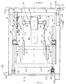
- FIG. 1 A base frame 1 and a platform 2 are arranged one above the other and connected to one another via a lifting scissor device 3.
- the position of the lifting scissor device can be changed by means of a drive 4.
- This contains a cam mechanism with two cams 5 and a shaft 6 which is mounted in the lifting scissor device 3.
- Each cam 5 is supported on its circumference on a roller 7, which are mounted in the base frame 1, but could also be mounted on the platform.
- the distance of the shaft 6 from the roller 7 is different and thus the spreading action of the lifting scissor device 3.
- the cam disc 5 forms part of an Archimedean spiral.
- a uniform slope of these spirals is chosen.
- it is also possible to use different gradients to choose different angular positions of the spiral, for example, the slope may be lower at the beginning than in the later course of this spiral.
- the lifting scissor device 3 contains two pairs of scissor levers 11, 12 and 13, 14, each of which is pivotally connected to one another via stub axles 15 and 16, respectively.
- the scissor levers 11 and 13 are connected to the base frame 1 via pivot bearings 17 and the pivot levers 12 and 14 are connected to the platform 2 via pivot bearings 18.
- the free ends of the pivot levers 11 and 13 are supported in guides 19 on the platform 2 and those of the scissor levers 12 and 14 in guides 20 on the base frame 1.
- Corresponding levers of the pairs of scissors are also connected to one another via coupling members 21 to 24, which are designed as tubes.
- pins with roller bearings 25 are provided for support on the guides 19, and in the extension of the tube 24, pins with roller bearings 26 are provided for support on the guides 20.
- the ends of the shaft 6 are supported in bearing blocks 27, 28 which are fastened to the pivot levers 11 and 13, respectively, so that the shaft 6 is carried along with the pivoting movement of these scissor levers 11, 13.
- Arms 29 are also attached to the tube 23 and serve to receive bearings for an output shaft 30 of the drive 4.
- Chain sprockets 31 are mounted on the shaft 30, which extends parallel to the tube 23, in order to drive corresponding chain sprockets 32, which are fixedly attached to the shaft 6, via a chain 33.
- the tube 23 is arranged to be adjustable relative to the scissor levers 11 and 13, i.e. at the ends of the tube 23 plates 34 are welded, which have slots 35 as guides, and can be screwed into the appropriate position by means of screws 36 on the respective pivot lever 11 or 13.
- the position of the plates 34 can be set correctly beforehand by means of set screws 37.
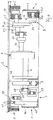
- the shaft 30 is the output shaft of a worm gear 40, which as such is self-locking, ie cannot be driven in reverse via the shaft 30.
- a controllable electric motor 41 drives the worm gear via a drive shaft, not shown, which extends perpendicular to the output shaft 30.
- the electric motor 41 is flanged to the housing of the worm gear 40, so to speak, floating freely.
- the rod 42 can be designed as a rubber metal element.
- An electric motor 41 preferably with a built-in brake, is used in order to bring the lift to an immediate standstill after the power supply has been interrupted.
- an incremental angle or displacement measuring device can also be accommodated, which enables the position of the lifting platform to be measured and indicated at any moment and is useful in a control loop for recording the actual value.
- the bearings 18 of the scissors levers 12 and 14 can be made height-adjustable, as indicated at 45 in FIG. 4.
- supports 46 can be provided which strike the angle frame 47 of the base frame 1 at the minimum height of the lifting platform.
- Cantilever arms 48 are welded to the angle iron 47 in the vicinity of the four corners of the lifting platform, of which two cantilever arms 48 are shown in FIG. 3 in order to be able to mount the lifting platform at a suitable location.
- the platform 2 also has cantilever arms 49 at the four corners in order to be able to attach a further construction, as required in the individual case.
- the lift operates as follows: By appropriately energizing the electric motor 41, the worm gear 40 is driven in the desired direction.
- the output shaft 30 drives the sprockets 31, which in turn drives the sprockets 32 via the chains 33.
- the shaft 6 rotates and thus also the cams 5. A piece of the circumference of these cams 5 rolls on the roller 7 and the distance between the roller 7 and the shaft 6 increases when the electric motor 41 is in its direction of rotation for extending the Lift has been driven, otherwise the distance is reduced. It is understood that when the end positions are reached, limit switches are actuated which shut down the motor 41.
- the location of the bearing blocks 27 and 28 along the scissor levers 11 and 13 can be selected to a certain extent and determines the extension height of the lifting platform. If the center distance of the shaft 6 is moved close to the axis formed by the stub axles 15 and 16, a greater spread of the swivel levers is achieved than with a larger axis distance from one another. So you have it in your hand to adapt to changing requirements in practice with regard to the desired extension length.
- a spatial cam carrier can also be used, which, for example, combines the three-dimensional shapes of the screw and the spiral.
- the new lift is simple and robust in its construction and allows to adapt to different requirements.
- the items used are commercially available and relatively inexpensive.
- the lifting platform is therefore also intended for applications in which lifting platforms have not previously been used for economic reasons.
Landscapes
- Life Sciences & Earth Sciences (AREA)
- Engineering & Computer Science (AREA)
- Geology (AREA)
- Mechanical Engineering (AREA)
- Structural Engineering (AREA)
- Transmission Devices (AREA)
- Forklifts And Lifting Vehicles (AREA)
Priority Applications (4)
| Application Number | Priority Date | Filing Date | Title |
|---|---|---|---|
| EP91113772A EP0528063A1 (fr) | 1991-08-15 | 1991-08-15 | Plateforme de levage |
| EP19910122043 EP0528072B1 (fr) | 1991-08-15 | 1991-12-21 | Plateforme de levage |
| DE59108233T DE59108233D1 (de) | 1991-08-15 | 1991-12-21 | Hebebühne |
| ES91122043T ES2095902T3 (es) | 1991-08-15 | 1991-12-21 | Plataforma elevadora. |
Applications Claiming Priority (1)
| Application Number | Priority Date | Filing Date | Title |
|---|---|---|---|
| EP91113772A EP0528063A1 (fr) | 1991-08-15 | 1991-08-15 | Plateforme de levage |
Publications (1)
| Publication Number | Publication Date |
|---|---|
| EP0528063A1 true EP0528063A1 (fr) | 1993-02-24 |
Family
ID=8207053
Family Applications (1)
| Application Number | Title | Priority Date | Filing Date |
|---|---|---|---|
| EP91113772A Withdrawn EP0528063A1 (fr) | 1991-08-15 | 1991-08-15 | Plateforme de levage |
Country Status (3)
| Country | Link |
|---|---|
| EP (1) | EP0528063A1 (fr) |
| DE (1) | DE59108233D1 (fr) |
| ES (1) | ES2095902T3 (fr) |
Cited By (1)
| Publication number | Priority date | Publication date | Assignee | Title |
|---|---|---|---|---|
| CN107043080A (zh) * | 2017-06-06 | 2017-08-15 | 安徽合力股份有限公司 | 一种自锁性的重载型升降平台 |
Citations (7)
| Publication number | Priority date | Publication date | Assignee | Title |
|---|---|---|---|---|
| FR879029A (fr) * | 1941-02-20 | 1943-02-11 | Appareil de levage | |
| US2862689A (en) * | 1955-11-03 | 1958-12-02 | Southworth Machine Co | Paper lift |
| DE1082023B (de) * | 1958-12-06 | 1960-05-19 | Ingo Trepel | Hebetisch mit Nuernberger Schere |
| FR1343743A (fr) * | 1962-10-12 | 1963-11-22 | Louis & Fils Ets | Table élévatrice |
| US4114854A (en) * | 1977-06-10 | 1978-09-19 | Pac-Craft Products, Inc. | Scissors lift work platform |
| CH664549A5 (en) * | 1984-10-08 | 1988-03-15 | Hans Fickler | Portable hoist for bed frame - has detachable mechanical coupling between two frames with supports on parallelogram linkages |
| EP0372246A1 (fr) * | 1988-12-06 | 1990-06-13 | Jlg Industries, Inc. | Appareil de levage d'une plate-forme |
-
1991
- 1991-08-15 EP EP91113772A patent/EP0528063A1/fr not_active Withdrawn
- 1991-12-21 DE DE59108233T patent/DE59108233D1/de not_active Revoked
- 1991-12-21 ES ES91122043T patent/ES2095902T3/es not_active Expired - Lifetime
Patent Citations (7)
| Publication number | Priority date | Publication date | Assignee | Title |
|---|---|---|---|---|
| FR879029A (fr) * | 1941-02-20 | 1943-02-11 | Appareil de levage | |
| US2862689A (en) * | 1955-11-03 | 1958-12-02 | Southworth Machine Co | Paper lift |
| DE1082023B (de) * | 1958-12-06 | 1960-05-19 | Ingo Trepel | Hebetisch mit Nuernberger Schere |
| FR1343743A (fr) * | 1962-10-12 | 1963-11-22 | Louis & Fils Ets | Table élévatrice |
| US4114854A (en) * | 1977-06-10 | 1978-09-19 | Pac-Craft Products, Inc. | Scissors lift work platform |
| CH664549A5 (en) * | 1984-10-08 | 1988-03-15 | Hans Fickler | Portable hoist for bed frame - has detachable mechanical coupling between two frames with supports on parallelogram linkages |
| EP0372246A1 (fr) * | 1988-12-06 | 1990-06-13 | Jlg Industries, Inc. | Appareil de levage d'une plate-forme |
Cited By (1)
| Publication number | Priority date | Publication date | Assignee | Title |
|---|---|---|---|---|
| CN107043080A (zh) * | 2017-06-06 | 2017-08-15 | 安徽合力股份有限公司 | 一种自锁性的重载型升降平台 |
Also Published As
| Publication number | Publication date |
|---|---|
| ES2095902T3 (es) | 1997-03-01 |
| DE59108233D1 (de) | 1996-10-31 |
Similar Documents
| Publication | Publication Date | Title |
|---|---|---|
| EP0501254B1 (fr) | Table élévatrice à ciseaux | |
| DE2251808C3 (de) | Zahnärztlicher Patientenstuhl mit Parallelogrammtragarm | |
| DE1192381B (de) | Laufkatze | |
| DE60102638T2 (de) | Gabelstapler | |
| EP0528072B1 (fr) | Plateforme de levage | |
| DE2742163A1 (de) | Handhabungsgeraet | |
| DE102017213236A1 (de) | Vorrichtung zur Aufnahme und zum Transport von Lasten | |
| EP0528063A1 (fr) | Plateforme de levage | |
| DE3212414A1 (de) | Strangfuehrungsgeruest fuer eine stranggiessanlage | |
| DE2923108C2 (de) | Treibwalzengerüst für eine Stranggießanlage | |
| DE2461084C3 (de) | Druckmittelbetriebene Stellvorrichtung für lineare und/oder drehende Bewegungen | |
| DE19521598C2 (de) | Lineargetriebe | |
| DE2430737B2 (de) | Drehtisch | |
| DE3812335A1 (de) | Zwangsfuehrung fuer paare von kurbelgetriebenen hub-, schub- und/oder zugelementen zur erzeugung einer parallelen linearen bewegung ihrer freien enden | |
| DE1212441B (de) | Einrichtung an einer Polierstrasse fuer durch eine Transportvorrichtung bewegte Werkstuecke mit aus Motor, Traeger und Polierscheibe bestehenden Polieraggregaten | |
| DE102010010730A1 (de) | Hubvorichtung einer Liegevorrichtung, bespielsweise einer Patientenliege | |
| EP0704404A1 (fr) | Plate-forme de levage | |
| DE3520871C1 (de) | Vorrichtung zur Fortbewegung von schweren Lasten | |
| DE19959458A1 (de) | Schränkmaschine | |
| EP0547377A2 (fr) | Support pour appareil à rayons X | |
| EP0661014A2 (fr) | Dispositif pour la variation de la hauteur et/ou de l'inclinaison d'une surface de travail | |
| DE3527324A1 (de) | Scherenhubtisch | |
| DE2938330A1 (de) | Hoehenverstellvorrichtung fuer ein zahnaerztliches geraet | |
| EP0300142A1 (fr) | Elévateur pour véhicules, à bras porteurs | |
| DE1477729A1 (de) | Vorrichtung,die ermoeglicht,ein Maschinenteil,das in irgendeinem Abstand geradlinig verschoben worden war,in eine zur Ausgangsstellung parallele Stellung zurueckzufuehren |
Legal Events
| Date | Code | Title | Description |
|---|---|---|---|
| PUAI | Public reference made under article 153(3) epc to a published international application that has entered the european phase |
Free format text: ORIGINAL CODE: 0009012 |
|
| AK | Designated contracting states |
Kind code of ref document: A1 Designated state(s): DE ES FR GB IT SE |
|
| 17P | Request for examination filed |
Effective date: 19930810 |
|
| STAA | Information on the status of an ep patent application or granted ep patent |
Free format text: STATUS: THE APPLICATION IS DEEMED TO BE WITHDRAWN |
|
| 18D | Application deemed to be withdrawn |
Effective date: 19950301 |