EP0528193B1 - Palier à bagues minces comportant une entaille de séparation et procédé de fabrication - Google Patents
Palier à bagues minces comportant une entaille de séparation et procédé de fabrication Download PDFInfo
- Publication number
- EP0528193B1 EP0528193B1 EP92112483A EP92112483A EP0528193B1 EP 0528193 B1 EP0528193 B1 EP 0528193B1 EP 92112483 A EP92112483 A EP 92112483A EP 92112483 A EP92112483 A EP 92112483A EP 0528193 B1 EP0528193 B1 EP 0528193B1
- Authority
- EP
- European Patent Office
- Prior art keywords
- bearing
- several
- rings
- thin ring
- thin
- Prior art date
- Legal status (The legal status is an assumption and is not a legal conclusion. Google has not performed a legal analysis and makes no representation as to the accuracy of the status listed.)
- Expired - Lifetime
Links
Images
Classifications
-
- F—MECHANICAL ENGINEERING; LIGHTING; HEATING; WEAPONS; BLASTING
- F16—ENGINEERING ELEMENTS AND UNITS; GENERAL MEASURES FOR PRODUCING AND MAINTAINING EFFECTIVE FUNCTIONING OF MACHINES OR INSTALLATIONS; THERMAL INSULATION IN GENERAL
- F16C—SHAFTS; FLEXIBLE SHAFTS; ELEMENTS OR CRANKSHAFT MECHANISMS; ROTARY BODIES OTHER THAN GEARING ELEMENTS; BEARINGS
- F16C19/00—Bearings with rolling contact, for exclusively rotary movement
- F16C19/02—Bearings with rolling contact, for exclusively rotary movement with bearing balls essentially of the same size in one or more circular rows
- F16C19/04—Bearings with rolling contact, for exclusively rotary movement with bearing balls essentially of the same size in one or more circular rows for radial load mainly
- F16C19/06—Bearings with rolling contact, for exclusively rotary movement with bearing balls essentially of the same size in one or more circular rows for radial load mainly with a single row or balls
-
- F—MECHANICAL ENGINEERING; LIGHTING; HEATING; WEAPONS; BLASTING
- F16—ENGINEERING ELEMENTS AND UNITS; GENERAL MEASURES FOR PRODUCING AND MAINTAINING EFFECTIVE FUNCTIONING OF MACHINES OR INSTALLATIONS; THERMAL INSULATION IN GENERAL
- F16C—SHAFTS; FLEXIBLE SHAFTS; ELEMENTS OR CRANKSHAFT MECHANISMS; ROTARY BODIES OTHER THAN GEARING ELEMENTS; BEARINGS
- F16C33/00—Parts of bearings; Special methods for making bearings or parts thereof
- F16C33/30—Parts of ball or roller bearings
- F16C33/58—Raceways; Race rings
- F16C33/60—Raceways; Race rings divided or split, e.g. comprising two juxtaposed rings
-
- F—MECHANICAL ENGINEERING; LIGHTING; HEATING; WEAPONS; BLASTING
- F16—ENGINEERING ELEMENTS AND UNITS; GENERAL MEASURES FOR PRODUCING AND MAINTAINING EFFECTIVE FUNCTIONING OF MACHINES OR INSTALLATIONS; THERMAL INSULATION IN GENERAL
- F16C—SHAFTS; FLEXIBLE SHAFTS; ELEMENTS OR CRANKSHAFT MECHANISMS; ROTARY BODIES OTHER THAN GEARING ELEMENTS; BEARINGS
- F16C33/00—Parts of bearings; Special methods for making bearings or parts thereof
- F16C33/30—Parts of ball or roller bearings
- F16C33/58—Raceways; Race rings
- F16C33/64—Special methods of manufacture
-
- F—MECHANICAL ENGINEERING; LIGHTING; HEATING; WEAPONS; BLASTING
- F16—ENGINEERING ELEMENTS AND UNITS; GENERAL MEASURES FOR PRODUCING AND MAINTAINING EFFECTIVE FUNCTIONING OF MACHINES OR INSTALLATIONS; THERMAL INSULATION IN GENERAL
- F16C—SHAFTS; FLEXIBLE SHAFTS; ELEMENTS OR CRANKSHAFT MECHANISMS; ROTARY BODIES OTHER THAN GEARING ELEMENTS; BEARINGS
- F16C2240/00—Specified values or numerical ranges of parameters; Relations between them
- F16C2240/40—Linear dimensions, e.g. length, radius, thickness, gap
- F16C2240/70—Diameters; Radii
- F16C2240/80—Pitch circle diameters [PCD]
- F16C2240/82—Degree of filling, i.e. sum of diameters of rolling elements in relation to PCD
Definitions
- the invention relates to a method for producing bearing rings, according to the preamble of claim 1 and a thin ring bearing and a bearing arrangement with such bearing rings.
- Thin section bearings are full-fledged roller bearings with an inner ring, an outer ring and rolling elements arranged between them.
- the bearing cross-section has the smallest possible dimensions in relation to the diameter and in relation to the rolling element size.
- the bearing cross section is preferably square.
- thin ring bearings Despite their small bearing cross-sections, thin ring bearings have the same level of accuracy in terms of bearing dimensions, concentricity and pitch as compared to normal rolling bearings. This requires complex production.
- the bearing rings for thin ring bearings are preferably made from pipe material and their contour is machined completely.
- a method for producing blanks for bearing rings which, starting from a band, is bent in a ring shape, alternatively also profiled and then connected, preferably welded, to the abutting edges. Then the blanks, which are then closed, are deburred and further processed into bearing rings.
- EP-A-0 319 842 it is also known to bend rolling bearing rings made of profiled material and to use them as slotted rings. However, these rings are not heat-treated and therefore have a lower material hardness.
- the invention is based on the object of finding a production method which is suitable for also producing rings for thin-ring bearings with at least one separation point, the high accuracies for these rings being maintained.
- Claim 7 describes a thin ring bearing with bearing rings produced by this method.
- Claim 8 describes a bearing arrangement with a thin ring bearing with bearing rings produced by the method according to the invention.
- the advantages achieved with the invention consist in particular in the more cost-effective production of thin-ring bearings according to the preamble of claim 1. Particularly due to the simultaneous bending and hardening, not only is economical production achieved, but also advantageously achieved the accuracy required for thin ring bearings in terms of roundness and vertical runout.
- Thin ring bearings of this type are preferably used for subordinate applications without machining according to claims 1 and 2.
- the highest levels of accuracy with regard to concentricity and pitch as well as all bearing dimensions are achieved. This process is used to produce high-quality thin-ring bearings in a simple manner.
- the bearings according to the invention particularly advantageously enable a 100% rolling element filling, which causes a doubling of the load capacity compared to previous thin ring bearings.
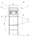
- the bearing has an outer ring 1 and an inner ring 2, between which 3 rolling elements 5 are arranged on raceways 3.
- Outer ring 1 and inner ring 2 each have at least one separation point 6.
- the bearing cross-section is square, that is Half the difference between the bearing outer diameter D and the bearing inner diameter d corresponds to the bearing width B. Since, in the exemplary embodiment, the rolling element diameter Dw is greater than 1/4 the difference between the bearing outer diameter D and the bearing inner diameter d, the described bearing is a thin ring bearing.
- Balls are used as rolling elements 5, which are separated and guided by a comb-shaped cage 7.
- the bearing can be formed with seals, not shown, between the outer ring 1 and the inner ring 2.
- the bearing rings 1, 2 are produced starting from pre-profiled or pre-profiled rod material. This is heated to the forging temperature and bent into coils of the required diameter, for example using a roll bending machine. If it is assumed that the material is pre-profiled, the shape of the bearing ring, in particular the final shape of the raceway 3, 4, is produced by shaping rolls in this operation. Hardening takes place directly from the heat of deformation by subsequent quenching using a suitable quenching liquid. After this step, the separation takes place in order to produce individual bearing rings from the helix. In order to achieve the required accuracy in terms of vertical runout and concentricity, straightening is required, preferably only straightening the prepared bearing rings in the direction of the bearing axis 8.
- the bearing rings have a surprisingly high degree of accuracy with regard to concentricity and pitch.
- the above-described operations are followed by grinding of the raceways 3, 4.
- the other surfaces of the bearing rings, in particular the outer bearing diameter D, the inner bearing diameter d and the side surfaces no longer have to be reworked.
- the rolling elements can be introduced in a known manner, for example via Konrad filling, between outer ring 1 and inner ring 2. A degree of filling of 50% is achieved. However, since the outer ring 1 has a separation point 6, a larger filling of the bearing with rolling elements can also be achieved. The outer ring 1 is locally bent elastically at the separation point 6, so that here there is a sufficient opening for introducing the rolling elements. This means that a fill level of up to 100% can be achieved.
- a cage 7 is then inserted between the rolling elements.
- the bearing can then be sealed with seals.
- the assembly can take place via a belt cage which is already filled with rolling elements 5 and which is pushed directly between the races 1, 2.
- the manufacturing tolerances of the bearing with regard to the diameter D, d and the raceways 3, 4 can be compensated.
- the bearing can be braced in accordance with claim 2.
Landscapes
- Engineering & Computer Science (AREA)
- General Engineering & Computer Science (AREA)
- Mechanical Engineering (AREA)
- Manufacturing & Machinery (AREA)
- Rolling Contact Bearings (AREA)
Claims (8)
- Procédé de fabrication de bagues de palier (1, 2) présentant au moins une fente (6), pour palier à bagues minces avec une section transversale de palier rectangulaire, de préférence carrée, caractérisé en ce qu'un barreau profilé est chauffé jusqu'à la température de forgeage, est cintré en hélice et est ensuite trempé par élimination brusque de la chaleur de déformation, l'hélice est ensuite découpée, dressée et soumise à revenu, et les chemins de roulement (3, 4) sont ensuite ou simultanément soumis à un usinage avec ou sans enlèvement de matière.
- Procédé selon la revendication 1, caractérisé en ce que les chemins de roulement (3, 4) sont façonnés par des cylindres à profiler pendant le cintrage et la trempe.
- Procédé selon la revendication 1 ou la revendication 2, caractérisé en ce que les chemins de roulement (3, 4) reçoivent leur forme finale par rectification après le découpage, le dressage et le revenu.
- Procédé selon la revendication 1 ou la revendication 2, caractérisé en ce que le dressage et le revenu s'effectuent en une seule opération.
- Procédé selon l'une ou plusieurs des revendications 1 à 4, caractérisé en ce que le dressage ne s'effectue que dans la direction de l'axe (8) du palier.
- Procédé selon une ou plusieurs des revendications 1 à 5, caractérisé en ce que les bagues de palier (1, 2) sont réalisées avec des fentes (6) s'étendant en oblique.
- Palier à bagues minces selon une ou plusieurs des revendications 1 à 6, caractérisé par un remplissage complet par des éléments de roulement (5).
- Agencement de palier présentant un palier à bagues minces réalisées selon l'une ou plusieurs de revendications 1 à 6, ou avec un palier à bagues minces selon la revendication 7, caractérisé en ce que le diamètre extérieur (D) du palier est légèrement plus grand que l'alésage intérieur de la structure de raccordement qui coopère avec lui, compte tenu de la plage totale de tolérance, et/ou en ce que le diamètre intérieur (d) du palier est légèrement plus petit que le diamètre extérieur de la structure de raccordement qui coopère avec lui, compte tenu de la plage totale de tolérance.
Applications Claiming Priority (2)
| Application Number | Priority Date | Filing Date | Title |
|---|---|---|---|
| DE4127213A DE4127213A1 (de) | 1991-08-16 | 1991-08-16 | Duennringlager |
| DE4127213 | 1991-08-16 |
Publications (3)
| Publication Number | Publication Date |
|---|---|
| EP0528193A2 EP0528193A2 (fr) | 1993-02-24 |
| EP0528193A3 EP0528193A3 (en) | 1993-05-19 |
| EP0528193B1 true EP0528193B1 (fr) | 1995-05-24 |
Family
ID=6438508
Family Applications (1)
| Application Number | Title | Priority Date | Filing Date |
|---|---|---|---|
| EP92112483A Expired - Lifetime EP0528193B1 (fr) | 1991-08-16 | 1992-07-21 | Palier à bagues minces comportant une entaille de séparation et procédé de fabrication |
Country Status (5)
| Country | Link |
|---|---|
| EP (1) | EP0528193B1 (fr) |
| JP (1) | JPH05196043A (fr) |
| CA (1) | CA2075128C (fr) |
| DE (2) | DE4127213A1 (fr) |
| ES (1) | ES2038107T3 (fr) |
Cited By (1)
| Publication number | Priority date | Publication date | Assignee | Title |
|---|---|---|---|---|
| DE102022127050A1 (de) | 2022-10-17 | 2024-04-18 | Schaeffler Technologies AG & Co. KG | Dichtungsanordnung, Wälzlager mit einer Dichtungsanordnung und Fahrzeug |
Families Citing this family (8)
| Publication number | Priority date | Publication date | Assignee | Title |
|---|---|---|---|---|
| JP3720469B2 (ja) * | 1996-07-18 | 2005-11-30 | Ntn株式会社 | プーリ |
| GB2348928B (en) | 1999-04-07 | 2001-10-31 | Bespak Plc | Improvements in or relating to dispensing apparatus |
| FR2792378B1 (fr) | 1999-04-16 | 2001-06-08 | Skf France | Palier a roulement rigide a billes |
| CN1260483C (zh) | 1999-07-19 | 2006-06-21 | 日本精工株式会社 | 滚珠轴承 |
| DE10240282B4 (de) * | 2002-08-31 | 2011-08-11 | Schaeffler Technologies GmbH & Co. KG, 91074 | Radialwälzlager |
| DE102005043071B3 (de) * | 2005-09-10 | 2007-04-26 | Ab Skf | Verfahren zur Herstellung eines Lagerringes |
| DE102013213928A1 (de) * | 2013-07-16 | 2015-01-22 | Schaeffler Technologies Gmbh & Co. Kg | Außenring und Rollenlager mit einem derartigen Außenring |
| DE102016208913A1 (de) * | 2016-05-24 | 2017-11-30 | Schaeffler Technologies AG & Co. KG | Verfahren zur Herstellung eines Dünnring-Rillenkugellagers, Dünnring-Rillenkugellager und Zweimassenschwungrad |
Citations (3)
| Publication number | Priority date | Publication date | Assignee | Title |
|---|---|---|---|---|
| DE1602446A1 (de) * | 1966-03-28 | 1973-05-24 | Fmc Corp | Herstellungsverfahren fuer laufringe |
| DE2460120A1 (de) * | 1974-12-19 | 1976-06-24 | Hoesch Werke Ag | Mittenfreies einreihiges drahtkugellager |
| EP0319842A1 (fr) * | 1987-12-10 | 1989-06-14 | INA Wälzlager Schaeffler KG | Procédé de réalisation d'un palier à roulements |
Family Cites Families (13)
| Publication number | Priority date | Publication date | Assignee | Title |
|---|---|---|---|---|
| DE1073248B (de) * | 1960-01-14 | Robert Zeuzem Frankfurt/M Fritz | Radial geteiltes Rollen oder Kugellager fur eingebaute gekröpfte Wellen | |
| DE305484C (fr) * | ||||
| FR353862A (fr) * | 1905-05-02 | 1905-09-22 | Frederick William Gurney | Coussinet à billes |
| US1715268A (en) * | 1927-04-01 | 1929-05-28 | Gen Motors Corp | Method of making bearings |
| GB417774A (en) * | 1934-04-30 | 1934-10-11 | Timken Roller Bearing Co | Improvements in the manufacture of raceway members for roller bearings |
| DE1726598U (de) * | 1956-03-06 | 1956-07-19 | Kugelfischer G Schaefer & Co | Ringe, insbesondere fuer grosse waelzlager. |
| DE1059251B (de) * | 1958-02-22 | 1959-06-11 | Duerkoppwerke Ag | Kaefigkugellager mit einem die Kugeln fuehrenden und haltenden Kammkaefig und mit Abdichtungsscheiben |
| US3166827A (en) * | 1963-03-21 | 1965-01-26 | Bushi Michael | Method of making a split ring |
| US3229353A (en) * | 1964-10-06 | 1966-01-18 | Skf Ind Inc | Method of making a bearing ring |
| DE1962776A1 (de) * | 1969-12-15 | 1971-06-16 | Townsend Claude Mortimer | Waelzlager mit Drahtlaufringen |
| JPS4938406A (fr) * | 1972-08-19 | 1974-04-10 | ||
| US4073551A (en) * | 1976-07-08 | 1978-02-14 | Freeway Corporation | Rolling type bearing and method for making same |
| DE3248634A1 (de) * | 1982-12-30 | 1984-07-12 | Jürgen Dr.-Ing. 8523 Baiersdorf Breme | Verfahren zur herstellung eines ringformkoerpers, insbesondere eines waelzlagerringrohlings |
-
1991
- 1991-08-16 DE DE4127213A patent/DE4127213A1/de not_active Withdrawn
-
1992
- 1992-07-21 EP EP92112483A patent/EP0528193B1/fr not_active Expired - Lifetime
- 1992-07-21 ES ES92112483T patent/ES2038107T3/es not_active Expired - Lifetime
- 1992-07-21 DE DE59202314T patent/DE59202314D1/de not_active Expired - Fee Related
- 1992-07-31 CA CA002075128A patent/CA2075128C/fr not_active Expired - Fee Related
- 1992-08-11 JP JP4214045A patent/JPH05196043A/ja active Pending
Patent Citations (3)
| Publication number | Priority date | Publication date | Assignee | Title |
|---|---|---|---|---|
| DE1602446A1 (de) * | 1966-03-28 | 1973-05-24 | Fmc Corp | Herstellungsverfahren fuer laufringe |
| DE2460120A1 (de) * | 1974-12-19 | 1976-06-24 | Hoesch Werke Ag | Mittenfreies einreihiges drahtkugellager |
| EP0319842A1 (fr) * | 1987-12-10 | 1989-06-14 | INA Wälzlager Schaeffler KG | Procédé de réalisation d'un palier à roulements |
Non-Patent Citations (1)
| Title |
|---|
| "Dünnringlager", Kaydon Corporation, Katalog 300 D, 2500-8410 * |
Cited By (1)
| Publication number | Priority date | Publication date | Assignee | Title |
|---|---|---|---|---|
| DE102022127050A1 (de) | 2022-10-17 | 2024-04-18 | Schaeffler Technologies AG & Co. KG | Dichtungsanordnung, Wälzlager mit einer Dichtungsanordnung und Fahrzeug |
Also Published As
| Publication number | Publication date |
|---|---|
| JPH05196043A (ja) | 1993-08-06 |
| DE4127213A1 (de) | 1993-02-18 |
| CA2075128A1 (fr) | 1993-02-17 |
| CA2075128C (fr) | 1996-08-27 |
| EP0528193A2 (fr) | 1993-02-24 |
| EP0528193A3 (en) | 1993-05-19 |
| ES2038107T3 (es) | 1995-07-16 |
| DE59202314D1 (de) | 1995-06-29 |
| ES2038107T1 (es) | 1993-07-16 |
Similar Documents
| Publication | Publication Date | Title |
|---|---|---|
| DE60019662T2 (de) | Lager für Radnabe eines Motorfahrzeuges und Befestigungsverfahren des Lagers in einer Motorfahrzeugaufhängung | |
| DE4228237C2 (de) | Verfahren zur Herstellung eines Lagerringes | |
| DE69614130T2 (de) | Verfahren zur herstellung eines linearlagers | |
| DE102019207525A1 (de) | Lenksäule für ein Kraftfahrzeug | |
| DE10240631B4 (de) | Axiallager und Herstellungsverfahren hierfür | |
| DE10331061B4 (de) | Ringförmige Verbundwerkstücke und Kaltwalzverfahren zu ihrer Fertigung | |
| DE69502119T2 (de) | Verfahren zur Herstellung von vorgespannten Kugelumlaufspindeln | |
| EP0528193B1 (fr) | Palier à bagues minces comportant une entaille de séparation et procédé de fabrication | |
| DE102011005326A1 (de) | Verfahren zur Herstellung eines Lagerringes, insbesondere für ein Kegelrollenlager | |
| WO2007090635A1 (fr) | Procédé de production de bagues dépourvues de symétrie de rotation et bague à came | |
| EP1649178A1 (fr) | Palier a roulement a parois minces | |
| DE2359050A1 (de) | Radial-axial-lager und verfahren zu seiner herstellung | |
| DE102009042166A1 (de) | Kugelrollenlager | |
| EP3325832A1 (fr) | Procédé de fabrication sans enlèvement de copeaux d'une bague de palier pour un palier à roulement et palier à roulement comprenant la bague de palier | |
| EP0745178A1 (fr) | Cames multiples | |
| DE10305074B4 (de) | Getriebewelle sowie Verfahren zur Herstellung einer Getriebewelle | |
| WO2008074560A2 (fr) | Procédé de fabrication d'un anneau de synchronisation d'un dispositif de synchronisation | |
| DE102020132822A1 (de) | Verfahren zur Herstellung eines inneren Anschlags in einem Rohrbauteil | |
| EP0927832A1 (fr) | Méthode de fabrication d'ébauches pour cages de joints universels | |
| EP2814633A1 (fr) | Procédé de montage d'un palier annulaire dans un boîtier de direction | |
| DE102019130286A1 (de) | Dichthülse mit kombinierten Axiallagermitteln für eine Druckmittel-Drehdurchführung | |
| DE102008050231A1 (de) | Wälzkörper | |
| EP3894105B1 (fr) | Procédé pour la préparation d'une piste de roulement à billes à la surface intérieure d'une pièce | |
| DE102018101551A1 (de) | Käfig für ein Wälzlager, Verfahren zum Fertigen des Käfigs sowie ein Käfigrohling | |
| DE19854523A1 (de) | Wälzlager und Verfahren zur Befestigung eines Lagerrings |
Legal Events
| Date | Code | Title | Description |
|---|---|---|---|
| PUAI | Public reference made under article 153(3) epc to a published international application that has entered the european phase |
Free format text: ORIGINAL CODE: 0009012 |
|
| AK | Designated contracting states |
Kind code of ref document: A2 Designated state(s): DE ES FR GB IT NL SE |
|
| GBC | Gb: translation of claims filed (gb section 78(7)/1977) | ||
| RAP1 | Party data changed (applicant data changed or rights of an application transferred) |
Owner name: FRIED. KRUPP AG HOESCH-KRUPP |
|
| ITCL | It: translation for ep claims filed |
Representative=s name: RICCARDI SERGIO & CO. |
|
| PUAL | Search report despatched |
Free format text: ORIGINAL CODE: 0009013 |
|
| TCNL | Nl: translation of patent claims filed | ||
| EL | Fr: translation of claims filed | ||
| AK | Designated contracting states |
Kind code of ref document: A3 Designated state(s): DE ES FR GB IT NL SE |
|
| 17P | Request for examination filed |
Effective date: 19930419 |
|
| 17Q | First examination report despatched |
Effective date: 19930812 |
|
| GRAA | (expected) grant |
Free format text: ORIGINAL CODE: 0009210 |
|
| AK | Designated contracting states |
Kind code of ref document: B1 Designated state(s): DE ES FR GB IT NL SE |
|
| ET | Fr: translation filed | ||
| REF | Corresponds to: |
Ref document number: 59202314 Country of ref document: DE Date of ref document: 19950629 |
|
| REG | Reference to a national code |
Ref country code: ES Ref legal event code: FG2A Ref document number: 2038107 Country of ref document: ES Kind code of ref document: T3 |
|
| GBT | Gb: translation of ep patent filed (gb section 77(6)(a)/1977) |
Effective date: 19950622 |
|
| ITF | It: translation for a ep patent filed | ||
| PLBE | No opposition filed within time limit |
Free format text: ORIGINAL CODE: 0009261 |
|
| STAA | Information on the status of an ep patent application or granted ep patent |
Free format text: STATUS: NO OPPOSITION FILED WITHIN TIME LIMIT |
|
| 26N | No opposition filed | ||
| REG | Reference to a national code |
Ref country code: GB Ref legal event code: IF02 |
|
| PGFP | Annual fee paid to national office [announced via postgrant information from national office to epo] |
Ref country code: GB Payment date: 20050711 Year of fee payment: 14 |
|
| PGFP | Annual fee paid to national office [announced via postgrant information from national office to epo] |
Ref country code: FR Payment date: 20050712 Year of fee payment: 14 |
|
| PGFP | Annual fee paid to national office [announced via postgrant information from national office to epo] |
Ref country code: DE Payment date: 20050714 Year of fee payment: 14 Ref country code: NL Payment date: 20050714 Year of fee payment: 14 Ref country code: SE Payment date: 20050714 Year of fee payment: 14 |
|
| PGFP | Annual fee paid to national office [announced via postgrant information from national office to epo] |
Ref country code: ES Payment date: 20050719 Year of fee payment: 14 |
|
| PG25 | Lapsed in a contracting state [announced via postgrant information from national office to epo] |
Ref country code: GB Free format text: LAPSE BECAUSE OF NON-PAYMENT OF DUE FEES Effective date: 20060721 |
|
| PG25 | Lapsed in a contracting state [announced via postgrant information from national office to epo] |
Ref country code: SE Free format text: LAPSE BECAUSE OF NON-PAYMENT OF DUE FEES Effective date: 20060722 |
|
| PGFP | Annual fee paid to national office [announced via postgrant information from national office to epo] |
Ref country code: IT Payment date: 20060731 Year of fee payment: 15 |
|
| PG25 | Lapsed in a contracting state [announced via postgrant information from national office to epo] |
Ref country code: NL Free format text: LAPSE BECAUSE OF NON-PAYMENT OF DUE FEES Effective date: 20070201 Ref country code: DE Free format text: LAPSE BECAUSE OF NON-PAYMENT OF DUE FEES Effective date: 20070201 |
|
| EUG | Se: european patent has lapsed | ||
| GBPC | Gb: european patent ceased through non-payment of renewal fee |
Effective date: 20060721 |
|
| NLV4 | Nl: lapsed or anulled due to non-payment of the annual fee |
Effective date: 20070201 |
|
| REG | Reference to a national code |
Ref country code: FR Ref legal event code: ST Effective date: 20070330 |
|
| REG | Reference to a national code |
Ref country code: ES Ref legal event code: FD2A Effective date: 20060722 |
|
| PG25 | Lapsed in a contracting state [announced via postgrant information from national office to epo] |
Ref country code: ES Free format text: LAPSE BECAUSE OF NON-PAYMENT OF DUE FEES Effective date: 20060722 |
|
| PG25 | Lapsed in a contracting state [announced via postgrant information from national office to epo] |
Ref country code: FR Free format text: LAPSE BECAUSE OF NON-PAYMENT OF DUE FEES Effective date: 20060731 |
|
| PG25 | Lapsed in a contracting state [announced via postgrant information from national office to epo] |
Ref country code: IT Free format text: LAPSE BECAUSE OF NON-PAYMENT OF DUE FEES Effective date: 20070721 |