EP0528556A2 - Reinigungsvorrichtung - Google Patents
Reinigungsvorrichtung Download PDFInfo
- Publication number
- EP0528556A2 EP0528556A2 EP92306872A EP92306872A EP0528556A2 EP 0528556 A2 EP0528556 A2 EP 0528556A2 EP 92306872 A EP92306872 A EP 92306872A EP 92306872 A EP92306872 A EP 92306872A EP 0528556 A2 EP0528556 A2 EP 0528556A2
- Authority
- EP
- European Patent Office
- Prior art keywords
- charge retentive
- retentive surface
- photoreceptor
- brush
- toner
- Prior art date
- Legal status (The legal status is an assumption and is not a legal conclusion. Google has not performed a legal analysis and makes no representation as to the accuracy of the status listed.)
- Granted
Links
Images


Classifications
-
- G—PHYSICS
- G03—PHOTOGRAPHY; CINEMATOGRAPHY; ANALOGOUS TECHNIQUES USING WAVES OTHER THAN OPTICAL WAVES; ELECTROGRAPHY; HOLOGRAPHY
- G03G—ELECTROGRAPHY; ELECTROPHOTOGRAPHY; MAGNETOGRAPHY
- G03G21/00—Arrangements not provided for by groups G03G13/00 - G03G19/00, e.g. cleaning, elimination of residual charge
- G03G21/0005—Arrangements not provided for by groups G03G13/00 - G03G19/00, e.g. cleaning, elimination of residual charge for removing solid developer or debris from the electrographic recording medium
- G03G21/0035—Arrangements not provided for by groups G03G13/00 - G03G19/00, e.g. cleaning, elimination of residual charge for removing solid developer or debris from the electrographic recording medium using a brush; Details of cleaning brushes, e.g. fibre density
-
- G—PHYSICS
- G03—PHOTOGRAPHY; CINEMATOGRAPHY; ANALOGOUS TECHNIQUES USING WAVES OTHER THAN OPTICAL WAVES; ELECTROGRAPHY; HOLOGRAPHY
- G03G—ELECTROGRAPHY; ELECTROPHOTOGRAPHY; MAGNETOGRAPHY
- G03G21/00—Arrangements not provided for by groups G03G13/00 - G03G19/00, e.g. cleaning, elimination of residual charge
- G03G21/0005—Arrangements not provided for by groups G03G13/00 - G03G19/00, e.g. cleaning, elimination of residual charge for removing solid developer or debris from the electrographic recording medium
Definitions
- This invention relates to a cleaning device, and more particularly to cleaning devices for removing residual toner and debris from a charge retentive surface of an image forming apparatus.
- a charge retentive surface of a photoreceptor is electrostatically charged, and exposed to a light pattern of an original image to be reproduced, to selectively discharge the photoreceptive surface in accordance therewith.
- the resulting pattern of charged and discharged areas on that surface form an electrostatic charge pattern (an electrostatic latent image) conforming to the original image.
- the latent image is developed by contacting it with a finely divided electrostatically attractable powder referred to as toner. Toner is held on the image areas by the electrostatic charge on the surface.
- toner is held on the image areas by the electrostatic charge on the surface.
- the toner image may then be transferred to a substrate (e.g., paper), and the image affixed thereto to form a permanent record of the image to be reproduced.
- a substrate e.g., paper
- the process is well know, and is useful for light lens copying from an original, and printing applications from electronically generated or stored originals, where a charged surface may be discharged in a variety of ways. Ion projection devices where a charge is imagewise deposited on a charge retentive substrate operate similarly.
- Multi-color electrophotographic printing is substantially identical to the foregoing process of black and white printing. However, rather than forming a single latent image on the photoreceptor, successive latent images corresponding to different colors are recorded thereon. Each single color electrostatic latent image is developed with toner of a color complementary thereto. This process is repeated in a plurality of cycles for differently colored images and their respective complementarily colored toner. Each single color toner image is transferred to the copy sheet in superimposed registration with the prior toner image. This creates a multi-layered toner image on the copy sheet. Thereafter, the multi- layered toner image is permanently affixed to the copy sheet as described above to create a color copy.
- the developer material (toner) may be a liquid material or a powder material.
- Blade cleaning is a highly desirable method for removal of residual toner and debris (hereinafter, collectively referred to as "toner") from a photoreceptor.
- toner residual toner and debris
- a relatively thin elastomeric blade member is provided and supported adjacent to and transversely across the photoreceptor surface with a blade edge chiseling or wiping toner from the surface.
- the released toner accumulating adjacent to the blade is transported away from the blade area by a toner transport arrangement, or by gravity.
- blade cleaning suffers from certain deficiencies, primarily resulting from the frictional sealing contact which must be maintained between the blade and the photoreceptor surface.
- Fig. 1 illustrates the manner in which comets are formed on the charge retentive surface of a photoreceptor 20.
- Photoreceptor 20 moves in the direction indicated by arrow 22.
- Toner particles 90 remaining on photoreceptor 20 after transfer of the toner image from the photoreceptor to a substrate (paper) are removed from the photoreceptor by a primary cleaning device such as, for example, a cleaning blade 110.
- Cleaning blade 110 is arranged at a low angle to the photoreceptor 20. Most of the toner particles accumulate upstream of blade 110 in the area denoted by reference numeral 93. This accumulated toner is then transported away by a toner transport arrangement or gravity. However, as illustrated in Fig.
- the tip of blade 110 can become bent due to the movement of photoreceptor 20, and the high friction forces generated between blade 110 and photoreceptor 20.
- some toner particles 91 can become located between the bent portion of blade 110 and the photoreceptor 20, where they are pressed into the photoreceptor with a high force. This causes these toner particles to melt and become permanently attached to the photoreceptor. Additional toner particles build up in front of these bonded toner particles with subsequent photoreceptor rotation and are also pressed into the photoreceptor 20 with a high force, causing the "comet tails" 92 to grow.
- this cleaning device should prevent high friction forces from being generated between a primary cleaning member and the photoreceptor to prevent toner particles from being pressed with high forces against the photoreceptor.
- a number of cleaning apparatus for photoreceptors which employ the combination of a brush and a cleaning blade are known.
- U.S. Patent No. 4,989,047 to Jugle et al discloses a photoreceptor cleaning apparatus for the reduction of agglomeration-caused spotting.
- a thin scraper member arranged at a low angle to the photoreceptor is provided as a secondary cleaning device to a rotating negatively biased fiber brush which contacts the surface of the photoreceptor upstream of the blade to remove most of the adhering toner particles.
- the rotating brush removes the preponderance of toner from the photoreceptor, and the blade removes any toner agglomerates formed on the photoreceptor by the agglomeration of toner, and toner and debris.
- U.S. Patent No. 4,364,660 to Oda discloses a photoreceptor cleaning system having a cleaning blade which removes toner from a photoreceptor.
- a fur brush located upstream of the cleaning blade acts as a toner recovery mechanism to recover toner removed from the photoreceptor by the cleaning blade.
- the brush is made from synthetic resin filaments having a diameter of 0.1mm. The brush rotates in a direction opposite from the photoreceptor to direct toner toward the blade.
- U.S. Patent No. 4,451,139 to Yanagawa et al discloses a cleaning apparatus for a photoreceptor which includes an elastic polyurethane cleaning blade located downstream of a rotating fur brush with respect to the rotation direction of the photoreceptor.
- U.S. Patent No. 3,918,808 to Narita discloses a photoreceptor developing and cleaning station wherein a cleaning blade is placed in a developing station which uses a magnetic brush to apply toner to a photoreceptor. Two complete revolutions of a photoreceptor are required to perform a single copying operation. During a first revolution, the blade is retracted. After transfer of a toner image from the photoreceptor to a copy sheet, the blade is contacted with the photoreceptor to remove residual toner from the photoreceptor.
- U.S. Patent No. 3,947,108 to Thettu et al discloses a photoreceptor cleaning system wherein a blade acts as a primary cleaning member.
- a brush located downstream of the blade removes a residual film from the photoreceptor not removed by the blade.
- the brush is abrasive and made from cotton or plastic fibers.
- U.S. Patent No. 4,875,081 to Goffe et al discloses a blade member for cleaning a photoreceptor wherein an A.C. voltage is applied to the cleaning blade.
- Use of the A.C. voltage eliminates the need to bias the blade against the photoreceptor with a high frictional force and thus, eliminates impaction of toner on the photoreceptor surface.
- U.S. Patent No, 4,835,807 to Swift discloses a cleaning brush for an electrostatographic reproducing apparatus which has electroconductive fibers of nylon filamentary polymer substrate having finely divided electrically conductive particles of carbon black suffused therein.
- a cleaning apparatus is provided with a rotating abrading brush, located upstream of a primary cleaner relative to a feeding direction of the charge retentive surface.
- the abrading brush contacts and abrades the charge retentive surface.
- the abrasion of the charge retentive surface reduces the friction between the charge retentive surface and a primary cleaner (which is preferably a cleaning blade biased against the charge retentive surface) and prevents the formation of comets on the charge retentive surface.
- the bristles which form the abrading brush are constructed from a material having a hardness greater than the hardness of the charge retentive surface so that the charge retentive surface is scratched by the bristles.
- the brush is rotated at a speed and contacted with a length of the charge retentive surface which are sufficient to cause scratches which reduce the coefficient of friction between the primary cleaning device and the charge retentive surface, but not so much as to damage the charge retentive surface, or to apply too much pressure to the residual toner particles on the charge retentive surface.
- the charge retentive surface cleaning apparatus will be described in combination with a particular color printer that uses a photoreceptor belt having a charge retentive surface.
- the cleaning apparatus of the present invention can be used with any printing apparatus that includes a charge retentive surface, including single color printers.
- the present invention is particularly applicable to any printer containing a charge retentive surface which is subject to the formation of comets thereon.
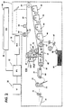
- FIG. 2 is a schematic elevational view of an illustrative electronic reprographic system incorporating an embodiment of the present invention therein. It will become evident from the following discussion that the present invention is equally well suited for use in a wide variety of printing systems, and is not necessarily limited in its application to the particular system shown herein.
- a multi-color original document 38 is positioned on a raster input scanner (RIS), indicated generally by the reference numeral 10.
- the RIS contains document illumination lamps, optics, a mechanical scanning drive, and a charge coupled device (CCD array).
- CCD array charge coupled device
- the RIS captures the entire original document and converts it to a series of raster scan lines and measures a set of primary color densities, i.e., red, green and blue densities, at each point of the original document.
- This information is transmitted to an image processing system (IPS), indicated generally by the reference numeral 12.
- IPS 12 is the control electronics which prepare and manage the image data flow to the raster output scanner (ROS), indicated generally by the reference numeral 16.
- ROS raster output scanner
- a user interface (UI), indicated generally by the reference numeral 14, is in communication with the IPS.
- the UI enables the operator to control the various operator adjustable functions.
- the output signal from the UI is transmitted to IPS 12.
- the signal corresponding to the desired image is transmitted from IPS 12 to ROS 16, which creates the output copy image.
- ROS 16 lays out the image in a series of horizontal scan lines with each line having a specified number of pixels per inch.
- the ROS includes a laser having a rotating polygon mirror block associated therewith.
- the ROS exposes the charged photoconductive surface of the printer, indicated generally by the reference numeral 18, to achieve a set of subtractive primary latent images.
- the latent images are developed with cyan, magenta, and yellow developer material, respectively. These developed images are transferred to a copy sheet in superimposed registration with one another to form a multi-colored image on the copy sheet. This multicolored image is then fused to the copy sheet forming a color copy.
- printer or marking engine 18 is an electrophotographic printing machine.
- the electrophotographic printing machine employs a photoconductive belt 20.
- the photoconductive belt 20 is an AMAT belt made from a polychromatic photoconductive material.
- Belt 20 moves in the direction of arrow 22 to advance successive portions of the photoconductive surface sequentially through the various processing stations disposed about the path of movement thereof.
- Belt 20 is entrained about transfer rollers 24 and 26, tensioning roller 28, and drive roller 30.
- Drive roller 30 is rotated by a motor 32 coupled thereto by suitable means such as a belt drive. As roller 30 rotates, it advances belt 20 in the direction of arrow 22.
- a corona generating device indicated generally by the reference numeral 34 charges photoconductive belt 20 to a relatively high, substantially uniform potential
- the exposure station includes the RIS 10 having a multi-colored original document 38 positioned thereat.
- the RIS captures the entire image from the original document 38 and converts it to a series of raster scan lines which are transmitted as electrical signals to IPS 12.
- the electrical signals from the RIS correspond to the red, green and blue densities at each point in the document.
- the IPS converts the set of red, green and blue density signals, i.e. the set of signals corresponding to the primary color densities of original document 38, to a set of colorimetric coordinates.
- UI 14 may be a touch screen or any other suitable control panel, providing an operator interface with the system.
- the output signals from the UI are transmitted to the IPS.
- the IPS then transmits signals corresponding to the desired image to ROS 16.
- ROS 16 includes a laser with rotating polygon mirror blocks. Preferably, a nine facet polygon is used.
- the ROS illuminates the charged portion of the photoconductive belt 20 at a rate of about 400 pixels per inch.
- the ROS will expose the photoconductive belt to record three latent images.
- One latent image is adapted to be developed with cyan developer material.
- Another latent image is adapted to be developed with magenta developer material with the third latent image being developed with yellow developer material.
- the latent images formed by the ROS on the photoconductive belt correspond to the signals from IPS 12.
- the development station includes four individual developer units generally indicated by the reference numerals 40, 42, 44 and 46.
- the developer units are of a type generally referred to in the art as "magnetic brush development units".
- a magnetic brush development system employs a magnetizable developer material including magnetic carrier granules having toner particles adhering triboelectrically thereto.
- the developer material is continually brought through a directional flux field to form a brush of developer material.
- the developer particles are continually moving so as to provide the brush consistently with fresh developer material. Development is achieved by bringing the brush of developer material into contact with the photoconductive surface.
- Developer units 40, 42 and 44 respectively, apply toner particles of a specific color which corresponds to the compliment of the specific color separated electrostatic latent image recorded on the photoconductive surface.
- the color of each of the toner particles is adapted to absorb light within a preselected spectral region of the electromagnetic wave spectrum.
- an electrostatic latent image formed by discharging the portions of charge on the photoconductive belt corresponding to the green regions of the original document will record the red and blue portions as areas of relatively high charge density on photoconductive belt 20, while the green areas will be reduced to a voltage level ineffective for development.
- the charged areas are then made visible by having developer unit 40 apply green absorbing (magenta) toner particles onto the electrostatic latent image recorded on photoconductive belt 20.
- developer unit 42 contains black toner particles and may be used to develop the electrostatic latent image formed from a black and white original document.
- Each of the developer units is moved into and out of the operative position.
- the magnetic brush In the operative position, the magnetic brush is closely adjacent to the photoconductive belt, while, in the non-operative position, the magnetic brush is spaced therefrom.
- the remaining developer units are in the non-operative position. This insures that each electrostatic latent image is developed with toner particles of the appropriate color without comingling.
- developer unit 40 is shown in the operative position with developer units 42, 44 and 46 being in the non-operative position.
- the toner image is moved to the transfer station where the toner image is transferred to a sheet of support material, such as, for example, plain paper.
- the sheet transport apparatus indicated generally by the reference numeral 48, moves the sheet into contact with photoconductive belt 20.
- Sheet transport 48 has a pair of spaced belts 54 entrained about rolls 50 and 52.
- a gripper extends between belts 54 and moves in unison therewith.
- the sheet is advanced from a stack of sheets 56 disposed on a tray.
- a friction retard feeder 58 advances the uppermost sheet from stack 56 onto a pre-transfer transport 60.
- Transport 60 advances the sheet to sheet transport 48.
- the sheet is advanced by transport 60 in synchronism with the movement of the gripper.
- the leading edge of the sheet arrives at a preselected position, i.e. a loading zone, to be received by the open gripper.
- the gripper then closes securing the sheet thereto for movement therewith in a recirculating path.
- the leading edge of the sheet is secured releasably by the gripper.
- a corona generating device 66 sprays ions onto the backside of the sheet so as to charge the sheet to the proper magnitude and polarity for attracting the toner image from photoconductive belt 20 thereto.
- the sheet remains secured to the gripper so as to move in a recirculating path for three cycles. In this way, three different color toner images are transferred to the sheet in superimposed registration with one another.
- the sheet may move in a recirculating path for four cycles when under color black removal is used and up to eight cycles when the information on two original documents is being merged onto a single copy sheet.
- Each of the electrostatic latent images recorded on the photoconductive surface is developed with the appropriately colored toner which is transferred, in superimposed registration with one another, to the sheet to form the multicolor copy of the colored original document.
- Conveyer 68 transports the sheet, in the direction of arrow 70, to the fusing station where the transferred image is permanently fused to the sheet.
- the fusing station includes heated fuser roll 74 and a pressure roll 72.
- the sheet passes through the nip defined by fuser roll 74 and pressure roll 72.
- the toner image contacts fuser roll 74 so as to be affixed to the sheet.
- the sheet is advanced by forwarding roll pairs 76 to catch tray 78 for subsequent removal therefrom by the machine operator.
- the cleaning device 100 for removing residual toner from photoreceptor 20 is illustrated in Figs. 3-5.
- Cleaning device 100 includes a primary cleaner such as, for example, an elongate cleaning blade 110 which removes the majority of residual toner particles from photoreceptor 20.
- Cleaning blade 110 is mounted to supporting structure by a bracket 112 in a manner similar to previous devices.
- the cleaning blade 110 is biased against photoreceptor 20 with a force sufficient to remove toner particles from the photoreceptor.
- high frictional forces tended to be created at the interface between cleaning blade 110 and the photoreceptor 20.
- the present invention prevents these high frictional forces from arising by abrading the charge retentive surface of the photoreceptor 20 with a rotating brush 140 located upstream of wiping blade 110 with respect to process direction 22.
- Rotating abrading brush 140 extends across the photoreceptor 20 (as does cleaning blade 110) so as to make contact with substantially the entire width of photoreceptor 20.
- Brush 140 includes a plurality of bristles having a hardness which is greater than a hardness of the charge retentive surface so that the bristles will scratch the charge retentive surface when contacted therewith. It has been determined that the best results are achieved by the present invention when the brush 140 is rotated in the direction (relative to photoreceptor 20) indicated by arrow 148 at a peripheral velocity which is three times that of photoreceptor 20. Additionally, the bristles of the abrading brush 140 should contact the charge retentive surface for a distance of at least 8 millimeters in the process direction.
- rotating abrading brush 140 is not biased (either electrically or magnetically), and thus, does not attract any of the toner particles from photoreceptor 20. Accordingly, brush 140 is ineffective at removing enough residual toner from photoreceptor 20 to act as a cleaning device.
- the scratches formed on the charge retentive surface of photoreceptor 20 are sufficient to reduce the frictional forces between cleaning blade 110 and photoreceptor 20, and thus prevents toner particles from being bonded to the charge retentive surface to prevent comets from forming.
- the majority of residual toner is removed from photoreceptor 20 by cleaning blade 110 and falls by gravity over and through the rotating abrading brush 140 and collects at a lower portion of housing 155.
- Housing 155 includes a cleaning member (flicker bar) 150 which contacts rotating abrading brush 140 to remove any toner which may adhere thereto from brush 140 (by flicking the toner from the brush). Additionally, a sealing member 158 is provided upstream of brush 140 to prevent toner particles from scattering outside of housing 155. The removed residual toner can be transported out of housing 155 by, for example, a conventional auger 160.
- Cleaning brush 140 can be constructed by spirally wrapping a support sheet having a plurality of bundles 141 of bristles 142 attached thereto (e.g., by weaving) around a shaft 144.
- the shaft can then be rotated by a separate motor 170, although preferably, the shaft is linked by gears to the motors which rotate photoreceptor 20 so that shaft 144 rotates at the appropriate speed.
- the bristles 142 are curved in a common direction with reference to the rotation direction 148 of shaft 144.
- the illustrated direction of curvature is preferred because it requires less torque to rotate the brush, and because any toner particles adhered to the bristles are removed more efficiently by flicker bar 150. However, other curvatures or no curvature will also work.
- the abrading brush 140 remains effective at sufficiently abrading the photoreceptor as long as the brush does not become clogged with removed toner particles. Accordingly, as stated above, brush 140 preferably is not magnetically or electrically biased. While the arrangement illustrated in Figs. 2 and 3 is not the most ideal arrangement because toner particles removed by blade 110 fall directly onto brush 140, it has been found that cleaning member 150 maintains brush sufficiently clean to operate satisfactory for extended periods of time. However, an arrangement where removed toner particles did not fall directly onto the abrading brush would result in an even longer brush life.
- the speed at which brush 140 is rotated relative to photoreceptor 20 must be such that a sufficient force is imparted to the brush bristles to cause them to scratch the charge retentive surface of the photoreceptor.
- the length of brush/photoreceptor contact in the process direction affects the size of the scratches formed in the photoreceptor. Although scratch length is not critical, preferably the scratches have a width in the range between 0.050 mm and 0.100 mm, and a depth in the range between 0.0005 mm and 0.002 mm. Additionally, the material which forms the bristles must be harder than the material which forms the charge retentive surface.
- the bristles were made from a material softer than the charge retentive layer of the photoreceptor, the bristle material would be deposited on the photoreceptor upon contact therewith.
- the outermost layer of the photoreceptor (the charge retentive layer) is made from a mixture of 50% polycarbonate and 50% N,N'-diphenyl-N,N'-bis(3'-methylphenyl)-(1,1'biphenyl)-4,4'-diamine
- a brush made from polypropylene bristles having a hardness of 93 on the Rockwell scale is capable of sufficiently scratching the photoreceptor.
- bristles made from a softer material such as polytetrafluoroethylene would not scratch the photoreceptor, and, in fact, would deposit polytetrafluoroethylene on the photoreceptor.
- the flexural modulus of the brush bristles is also an important factor.
- the polypropylene bristles had a flexural modulus of 1650 newtons/mm2. Polypropylene bristles with half the flexural modulus would not sufficiently scratch the photoreceptor.
- the characteristics of the brush bristles will depend on the material which forms the outer layer of the photoreceptor.
- the characteristic of the present invention which results in the reduction of comets is the amount of photoreceptor scratching which takes place.
- the photoreceptor must be scratched (abraded) enough to reduce the coefficient of friction between the primary cleaning device (e.g., the cleaning blade) and the photoreceptor, but not so much as to damage the photoreceptor, or to apply so much pressure to the residual toner particles that they melt and adhere to the photoreceptor.
- the coefficient of friction between the cleaning blade and the illustrated photoreceptor belt must be maintained ator below 0.9 to prevent toner particles from being adhered thereto. Scratches having a size in the above described range were sufficient to maintain an appropriate coefficient of friction between a blade and a photoreceptor belt having the above described composition.
- the photoreceptor belt While it maybe possible to construct the photoreceptor belt to have an outer surface which results in a sufficiently low coefficient of friction when pressed against a cleaning blade, this may not be practical due to manufacturing practices.
- the illustrative belt may not be subject to cometing when used with a different type of cleaner (i.e., a non-blade cleaner), or with a different type of toner. It may not be desirable to alter the surface characteristics of the belt when used in these different machines. Accordingly, the present invention permits a single type of belt to be used in different machines without altering the belt for each machine.
- a cleaning device was constructed and integrated with a color copier.
- the copier employed an AMAT belt (wherein a binder generator layer is sandwiched between a support substrate and a charge transport layer).
- AMAT belts are well known in general, and can be constructed, for example, according to the teachings of U.S. Patent Application No. 07/618,731 (Attorney Docket No. JAO 26249), filed November 27, 1990 to Charles C. Robinette et al, the disclosure of which is incorporated herein by reference.
- the exemplative photoreceptor included four layers.
- the uppermost outer layer had a thickness of 30 microns and was comprised of a mixture of 50% polycarbonate and 50% N,N'-diphenyl-N,N'-bis(3'- methylphenyl)-(1,1'biphenyl)-4,4'-diamine.
- the second layer had a thickness of 2.3 microns and comprised 7% selenium, 69% vinyl-carbazole, and 24% N,N'-diphenyl-N,N'-bis(3'-methylphenyl)- (1,1'biphenyl)-4,4'-diamine.
- the third layer (ground plane) had a thickness of 115 Angstroms and comprised titanium.
- the fourth layer (back layer) had a thickness of 3 mil and comprised polyethylene.
- the cleaning device was constructed according to the following parameters.
- the blade was a urethane blade having a thickness of 2 millimeters. Such a blade can be purchased from Acushnet Rubber Co., New Bedford, Mass., Xerox material Spec. No. 91-0346.
- the blade was biased against the photoreceptor with a force of 23 grams per centimeter of length.
- the abrading brush included a plurality of polypropylene bristles having a length of 7.5 millimeters and a size (diameter) of 17 Denier.
- the bristles (or fibers) were provided in bundles of 45 fibers per bundle.
- This brush was purchased from Tsuchiya Co., Ltd., 4F Fujika Bldg., 2-2-2 Yotsuya, Shinjokuku, Tokyo, Japan.
- the brush 140 was arranged with respect to the photoreceptor so that the bristles would contact the photoreceptor for at least 8 millimeters in the process direction.
- the photoreceptor was rotated at a peripheral velocity of 190 mm/sec, and the brush was rotated at a peripheral velocity of 570 mm/sec.
- the present invention is described with reference to a preferred embodiment, this particular embodiment is intended to be illustrative and not limiting.
- the present invention can be used with imaging systems employing a photoreceptor drum instead of a belt as long as the brush sufficiently scratches the outermost photoreceptor layer.
- the abrading brush of the present invention can be used in combination with primary cleaners other than blades, particularly when the formation of comets is a problem.
- Various modifications may be made without departing from the scope of the invention as defined in the appended claims.
Landscapes
- Physics & Mathematics (AREA)
- General Physics & Mathematics (AREA)
- Cleaning In Electrography (AREA)
Applications Claiming Priority (2)
| Application Number | Priority Date | Filing Date | Title |
|---|---|---|---|
| US748141 | 1991-08-21 | ||
| US07/748,141 US5175591A (en) | 1991-08-21 | 1991-08-21 | Cleaning device including abrading cleaning brush for comet control |
Publications (3)
| Publication Number | Publication Date |
|---|---|
| EP0528556A2 true EP0528556A2 (de) | 1993-02-24 |
| EP0528556A3 EP0528556A3 (en) | 1993-05-26 |
| EP0528556B1 EP0528556B1 (de) | 1996-10-02 |
Family
ID=25008204
Family Applications (1)
| Application Number | Title | Priority Date | Filing Date |
|---|---|---|---|
| EP92306872A Expired - Lifetime EP0528556B1 (de) | 1991-08-21 | 1992-07-28 | Reinigungsvorrichtung |
Country Status (6)
| Country | Link |
|---|---|
| US (1) | US5175591A (de) |
| EP (1) | EP0528556B1 (de) |
| JP (1) | JP3211985B2 (de) |
| BR (1) | BR9203198A (de) |
| DE (1) | DE69214232T2 (de) |
| MX (1) | MX9204751A (de) |
Cited By (1)
| Publication number | Priority date | Publication date | Assignee | Title |
|---|---|---|---|---|
| NO20181124A1 (no) * | 2018-01-25 | 2019-07-26 | Aqua Robotics As | Roterbar børste for et neddykkbart rengjøringsapparat |
Families Citing this family (13)
| Publication number | Priority date | Publication date | Assignee | Title |
|---|---|---|---|---|
| US5797078A (en) * | 1993-07-09 | 1998-08-18 | Xerox Corporation | Photoreceptor comet prevention brush |
| US5339149A (en) * | 1993-08-23 | 1994-08-16 | Xerox Corporation | Non-stick spots blade |
| US5434657A (en) * | 1994-06-29 | 1995-07-18 | Xerox Corporation | Brush for applying release agent to intermediate transfer member |
| US5556499A (en) * | 1994-12-01 | 1996-09-17 | Polaroid Corporation | Delaminating method and apparatus |
| US5689791A (en) * | 1996-07-01 | 1997-11-18 | Xerox Corporation | Electrically conductive fibers |
| KR100219658B1 (ko) * | 1997-08-26 | 1999-09-01 | 윤종용 | 습식 프린터의 현상장치 |
| KR100234282B1 (ko) * | 1997-08-27 | 1999-12-15 | 윤종용 | 습식 전자사진방식 프린터의 감광벨트 크리닝장치 |
| JP3752820B2 (ja) * | 1998-02-27 | 2006-03-08 | コニカミノルタビジネステクノロジーズ株式会社 | カラー画像形成装置 |
| JP4712946B2 (ja) * | 2000-08-23 | 2011-06-29 | 東芝テック株式会社 | クリーニング装置およびこのクリーニング装置を備えた画像形成装置 |
| US6925282B2 (en) * | 2003-09-26 | 2005-08-02 | Xerox Corporation | Retractable agglomeration removable blade with cleaning mechanism and process for agglomeration removal |
| JP4144899B1 (ja) * | 2007-01-22 | 2008-09-03 | キヤノン株式会社 | 再生弾性ローラの製造方法 |
| US7633689B2 (en) * | 2007-07-18 | 2009-12-15 | Asml Holding N.V. | Catadioptric optical system for scatterometry |
| JP2009282343A (ja) * | 2008-05-23 | 2009-12-03 | Konica Minolta Business Technologies Inc | クリーニング装置及び画像形成装置 |
Family Cites Families (14)
| Publication number | Priority date | Publication date | Assignee | Title |
|---|---|---|---|---|
| US3918808A (en) * | 1972-12-21 | 1975-11-11 | Ricoh Kk | Photoreceptor cleaning device for electrophotographic copying apparatus of the dry cleaning agent type |
| US3947108A (en) * | 1974-05-20 | 1976-03-30 | Xerox Corporation | Cleaning system |
| US4364660A (en) * | 1979-05-29 | 1982-12-21 | Tokyo Shibaura Denki Kabushiki Kaisha | Apparatus for and method of cleaning a photo-sensitive body with cleaning blade brought gradually into contact with body |
| US4436412A (en) * | 1981-05-20 | 1984-03-13 | Mita Industrial Company Limited | Cleaning device for use on an electrostatic copying apparatus |
| JPS5840578A (ja) * | 1981-09-04 | 1983-03-09 | Ricoh Co Ltd | クリ−ニング装置の脱着装置 |
| JPS60134272A (ja) * | 1983-12-23 | 1985-07-17 | Canon Inc | クリ−ニング装置 |
| US4835807A (en) * | 1988-01-28 | 1989-06-06 | Xerox Corporation | Cleaning brush |
| JPH0274180A (ja) * | 1988-09-09 | 1990-03-14 | Nec Corp | 速度検出器 |
| US4875081A (en) * | 1988-10-24 | 1989-10-17 | Xerox Corporation | Electrophotographic device having a.c. biased cleaning member |
| JP2741879B2 (ja) * | 1988-12-20 | 1998-04-22 | 株式会社リコー | 電子写真装置のクリーニング装置 |
| JP2633016B2 (ja) * | 1989-04-05 | 1997-07-23 | キヤノン株式会社 | プロセスカートリッジ及び画像形成装置 |
| JP2519322B2 (ja) * | 1989-06-09 | 1996-07-31 | 株式会社東芝 | α線のインラインモニタ装置 |
| US4986526A (en) * | 1989-09-25 | 1991-01-22 | Xerox Corporation | Sheet registration calibration |
| US4989047A (en) * | 1989-12-11 | 1991-01-29 | Xerox Corporation | Cleaning apparatus for the reduction of agglomeration-caused spotting |
-
1991
- 1991-08-21 US US07/748,141 patent/US5175591A/en not_active Expired - Fee Related
-
1992
- 1992-07-28 DE DE69214232T patent/DE69214232T2/de not_active Expired - Fee Related
- 1992-07-28 EP EP92306872A patent/EP0528556B1/de not_active Expired - Lifetime
- 1992-08-12 JP JP21507192A patent/JP3211985B2/ja not_active Expired - Fee Related
- 1992-08-17 MX MX9204751A patent/MX9204751A/es unknown
- 1992-08-18 BR BR929203198A patent/BR9203198A/pt not_active IP Right Cessation
Cited By (3)
| Publication number | Priority date | Publication date | Assignee | Title |
|---|---|---|---|---|
| NO20181124A1 (no) * | 2018-01-25 | 2019-07-26 | Aqua Robotics As | Roterbar børste for et neddykkbart rengjøringsapparat |
| NO344164B1 (no) * | 2018-01-25 | 2019-09-23 | Aqua Robotics As | Roterbar børste for et neddykkbart rengjøringsapparat |
| DK181512B1 (en) * | 2018-01-25 | 2024-03-20 | Aqua Robotics As | Cleaning device for a submerged surface |
Also Published As
| Publication number | Publication date |
|---|---|
| US5175591A (en) | 1992-12-29 |
| EP0528556A3 (en) | 1993-05-26 |
| MX9204751A (es) | 1993-04-01 |
| DE69214232D1 (de) | 1996-11-07 |
| DE69214232T2 (de) | 1997-03-06 |
| JP3211985B2 (ja) | 2001-09-25 |
| EP0528556B1 (de) | 1996-10-02 |
| JPH05197318A (ja) | 1993-08-06 |
| BR9203198A (pt) | 1993-04-06 |
Similar Documents
| Publication | Publication Date | Title |
|---|---|---|
| EP0528556B1 (de) | Reinigungsvorrichtung | |
| US4878093A (en) | Dual roll cleaning apparatus for charge retentive surface | |
| US5797078A (en) | Photoreceptor comet prevention brush | |
| US10126686B2 (en) | Image forming apparatus including cleaning unit with brush roller, rotatable member, and blade member | |
| US4786943A (en) | Device for removing residual developer particles from a photoconductive member | |
| US6775512B2 (en) | Dual electrostatic brush cleaner bias switching for multiple pass cleaning of high density toner inputs | |
| US6980765B2 (en) | Dual polarity electrostatic brush cleaner | |
| US6134405A (en) | Combined charging and cleaning blade | |
| JPH037977A (ja) | 画像形成装置 | |
| EP1089141B1 (de) | Reinigungsgerät | |
| US5077578A (en) | Development system | |
| US5923940A (en) | Cleaning brush having fibers of different lengths | |
| US8953968B2 (en) | Air-bearing photoreceptor backer bar for eliminating transfer streaks | |
| JP3852222B2 (ja) | 画像形成装置 | |
| JP2812532B2 (ja) | 感光体ベルトによるシート搬送装置 | |
| JPH10293512A (ja) | 画像形成装置 | |
| JPH112934A (ja) | 画像形成装置 | |
| EP0784248B1 (de) | Elektrostatographische Tonerbild-Herstellungsstation | |
| JP2812533B2 (ja) | 感光体ベルトによるシート搬送装置 | |
| US5241352A (en) | Air detoned cleaner brush | |
| JP4927680B2 (ja) | 柔らかい接触部のフリッカーバー組立体及びこれを含むトナー画像複製機 | |
| JP4326852B2 (ja) | 画像形成装置 | |
| JP2004325657A (ja) | 画像形成装置 | |
| JPH012083A (ja) | 感光体クリ−ニング装置 | |
| JP3151688B2 (ja) | 画像形成装置 |
Legal Events
| Date | Code | Title | Description |
|---|---|---|---|
| PUAI | Public reference made under article 153(3) epc to a published international application that has entered the european phase |
Free format text: ORIGINAL CODE: 0009012 |
|
| AK | Designated contracting states |
Kind code of ref document: A2 Designated state(s): DE FR GB |
|
| PUAL | Search report despatched |
Free format text: ORIGINAL CODE: 0009013 |
|
| AK | Designated contracting states |
Kind code of ref document: A3 Designated state(s): DE FR GB |
|
| 17P | Request for examination filed |
Effective date: 19931105 |
|
| 17Q | First examination report despatched |
Effective date: 19950206 |
|
| GRAH | Despatch of communication of intention to grant a patent |
Free format text: ORIGINAL CODE: EPIDOS IGRA |
|
| GRAH | Despatch of communication of intention to grant a patent |
Free format text: ORIGINAL CODE: EPIDOS IGRA |
|
| GRAA | (expected) grant |
Free format text: ORIGINAL CODE: 0009210 |
|
| AK | Designated contracting states |
Kind code of ref document: B1 Designated state(s): DE FR GB |
|
| REF | Corresponds to: |
Ref document number: 69214232 Country of ref document: DE Date of ref document: 19961107 |
|
| ET | Fr: translation filed | ||
| PLBE | No opposition filed within time limit |
Free format text: ORIGINAL CODE: 0009261 |
|
| STAA | Information on the status of an ep patent application or granted ep patent |
Free format text: STATUS: NO OPPOSITION FILED WITHIN TIME LIMIT |
|
| 26N | No opposition filed | ||
| REG | Reference to a national code |
Ref country code: GB Ref legal event code: IF02 |
|
| PGFP | Annual fee paid to national office [announced via postgrant information from national office to epo] |
Ref country code: FR Payment date: 20030711 Year of fee payment: 12 |
|
| PGFP | Annual fee paid to national office [announced via postgrant information from national office to epo] |
Ref country code: GB Payment date: 20030723 Year of fee payment: 12 |
|
| PGFP | Annual fee paid to national office [announced via postgrant information from national office to epo] |
Ref country code: DE Payment date: 20030807 Year of fee payment: 12 |
|
| PG25 | Lapsed in a contracting state [announced via postgrant information from national office to epo] |
Ref country code: GB Free format text: LAPSE BECAUSE OF NON-PAYMENT OF DUE FEES Effective date: 20040728 |
|
| PG25 | Lapsed in a contracting state [announced via postgrant information from national office to epo] |
Ref country code: DE Free format text: LAPSE BECAUSE OF NON-PAYMENT OF DUE FEES Effective date: 20050201 |
|
| GBPC | Gb: european patent ceased through non-payment of renewal fee |
Effective date: 20040728 |
|
| PG25 | Lapsed in a contracting state [announced via postgrant information from national office to epo] |
Ref country code: FR Free format text: LAPSE BECAUSE OF NON-PAYMENT OF DUE FEES Effective date: 20050331 |
|
| REG | Reference to a national code |
Ref country code: FR Ref legal event code: ST |