EP0530183B1 - Dichtung für kreisförmigen wärmetauscher - Google Patents
Dichtung für kreisförmigen wärmetauscher Download PDFInfo
- Publication number
- EP0530183B1 EP0530183B1 EP90913624A EP90913624A EP0530183B1 EP 0530183 B1 EP0530183 B1 EP 0530183B1 EP 90913624 A EP90913624 A EP 90913624A EP 90913624 A EP90913624 A EP 90913624A EP 0530183 B1 EP0530183 B1 EP 0530183B1
- Authority
- EP
- European Patent Office
- Prior art keywords
- heat exchanger
- core
- exchanger according
- sealing
- tongue
- Prior art date
- Legal status (The legal status is an assumption and is not a legal conclusion. Google has not performed a legal analysis and makes no representation as to the accuracy of the status listed.)
- Expired - Lifetime
Links
- 238000007789 sealing Methods 0.000 title claims description 82
- 239000012530 fluid Substances 0.000 claims abstract description 60
- 238000004891 communication Methods 0.000 claims description 4
- 239000007789 gas Substances 0.000 abstract description 15
- 230000008602 contraction Effects 0.000 abstract description 2
- 238000010276 construction Methods 0.000 description 8
- 238000003466 welding Methods 0.000 description 8
- 125000006850 spacer group Chemical group 0.000 description 4
- 229910052751 metal Inorganic materials 0.000 description 3
- 230000008646 thermal stress Effects 0.000 description 3
- 238000002485 combustion reaction Methods 0.000 description 2
- 125000004122 cyclic group Chemical group 0.000 description 2
- 230000007613 environmental effect Effects 0.000 description 2
- 239000000835 fiber Substances 0.000 description 2
- 239000000446 fuel Substances 0.000 description 2
- 239000002184 metal Substances 0.000 description 2
- 230000000717 retained effect Effects 0.000 description 2
- 239000003351 stiffener Substances 0.000 description 2
- OKTJSMMVPCPJKN-UHFFFAOYSA-N Carbon Chemical class [C] OKTJSMMVPCPJKN-UHFFFAOYSA-N 0.000 description 1
- RYGMFSIKBFXOCR-UHFFFAOYSA-N Copper Chemical compound [Cu] RYGMFSIKBFXOCR-UHFFFAOYSA-N 0.000 description 1
- 239000003575 carbonaceous material Substances 0.000 description 1
- 239000000567 combustion gas Substances 0.000 description 1
- 239000010949 copper Substances 0.000 description 1
- 229910052802 copper Inorganic materials 0.000 description 1
- 230000000694 effects Effects 0.000 description 1
- 239000002657 fibrous material Substances 0.000 description 1
- 239000000463 material Substances 0.000 description 1
- 239000007769 metal material Substances 0.000 description 1
- 229910001220 stainless steel Inorganic materials 0.000 description 1
- 239000010935 stainless steel Substances 0.000 description 1
- 238000011144 upstream manufacturing Methods 0.000 description 1
Images


Classifications
-
- F—MECHANICAL ENGINEERING; LIGHTING; HEATING; WEAPONS; BLASTING
- F28—HEAT EXCHANGE IN GENERAL
- F28D—HEAT-EXCHANGE APPARATUS, NOT PROVIDED FOR IN ANOTHER SUBCLASS, IN WHICH THE HEAT-EXCHANGE MEDIA DO NOT COME INTO DIRECT CONTACT
- F28D9/00—Heat-exchange apparatus having stationary plate-like or laminated conduit assemblies for both heat-exchange media, the media being in contact with different sides of a conduit wall
- F28D9/0012—Heat-exchange apparatus having stationary plate-like or laminated conduit assemblies for both heat-exchange media, the media being in contact with different sides of a conduit wall the apparatus having an annular form
- F28D9/0018—Heat-exchange apparatus having stationary plate-like or laminated conduit assemblies for both heat-exchange media, the media being in contact with different sides of a conduit wall the apparatus having an annular form without any annular circulation of the heat exchange media
-
- F—MECHANICAL ENGINEERING; LIGHTING; HEATING; WEAPONS; BLASTING
- F28—HEAT EXCHANGE IN GENERAL
- F28F—DETAILS OF HEAT-EXCHANGE AND HEAT-TRANSFER APPARATUS, OF GENERAL APPLICATION
- F28F2230/00—Sealing means
-
- F—MECHANICAL ENGINEERING; LIGHTING; HEATING; WEAPONS; BLASTING
- F28—HEAT EXCHANGE IN GENERAL
- F28F—DETAILS OF HEAT-EXCHANGE AND HEAT-TRANSFER APPARATUS, OF GENERAL APPLICATION
- F28F2265/00—Safety or protection arrangements; Arrangements for preventing malfunction
- F28F2265/26—Safety or protection arrangements; Arrangements for preventing malfunction for allowing differential expansion between elements
Definitions
- This invention relates generally to a heat exchanger and more particularly to the construction of a circular heat exchanger being removably attachable to an engine and being sealed therebetween comprising the features as indicated in the preamble of claim 1.
- a heat exchanger is known, for example, from US-A-4 582 126.
- recuperator for a gas turbine engine must be capable of operating at temperatures of between about 500°C and 700°C and internal pressures of between approximately 450 kPa and 1400 kPa under operating conditions involving repeated starting and stopping cycles.
- Such circular recuperators include a core which is commonly constructed of a plurality of relatively thin flat sheets having an angled or corrugated spacer fixedly attached therebetween.
- the sheets are joined into cells and sealed at opposite sides and form passages between the sheets.
- These cells are stacked or rolled and form alternative air cells and hot exhaust cells.
- Compressed discharged air from a compressor of the engine passes through the air cells while hot exhaust gas flows through alternate cells. The exhaust gas heats the sheets and the spacers, and the compressor discharged air is heated by conduction from the sheets and spacers.
- the recuperator comprises a hollow cylindrical inner shell and a concentric outer shell separated by a convoluted separator sheet which is wound over and around several corrugated sheets forming a series of corrugated air cores and combustion gas cores.
- the corrugated sheets are metallically bonded to the separator sheets in an attempt to increase efficiency.
- One of the problems with such a system is its lack of efficiency and the ability to test or inspect individual passages prior to assembly into a finished heat exchanger.
- the concentric outer shell is exposed to the recuperator temperatures on one side and to the environmental temperature on the other side.
- the recuperator expands and contracts due to start up and shut down, the thermal stress and strain induced in the core at the point of connection between the convoluted separator sheets, the corrugated sheets and the concentric outer shell will be greatly varied and reduce the longevity of the structure.
- a simple plate construction includes an inner cylindrical casing and an outer annular casing having a common axis. Radially disposed plates form passages A and B which alternately flow a cooler fluid and a hotter fluid. A corrugated plate being progressively narrower in width toward the heat exchanger axis is positioned in the passage A and a corrugated plate being progressively increasing in width toward the axis is positioned in the passage B.
- One of the problems with such a system is its lack of efficiency.
- the outer annular casing is exposed to the recuperator temperatures on one side and to the environmental temperature on the other side. Thus, as the recuperator expands and contracts due to start up and shut down, the thermal stress and strain induced in the core at the point of connection between the radially disposed plates and the outer casing will be greatly varied and reduce the longevity of the structure.
- a radial flow regenerator includes a plurality of heat transfer segments formed by a number of laid-up thin corrugated sheet metal strips or shims. The segments are mounted between stiffeners, and a bridge is positioned in notches and secured to the segments.
- the regenerator while providing a radial flow, fails to efficiently make use of the entire heat exchange area.
- the stiffeners and bridges are positioned in an area which could be used for heat transferring purposes.
- the cost and complexity of the structure is greatly increased because of the notches and complex shapes of the control beams.
- FIG. 3 Another example of a heat exchanger construction is disclosed in U.S. -A- 3,759,323.
- a primary surface plate-type heat exchanger construction is shown and uses a plurality of flat successively stacked sheets having a plurality of edge bars for spacing the sheets apart. A large number of sheets are stacked in pairs with the edge bars therebetween to form a heat exchange core of a desired size.
- a plurality of heat exchanger cores are positioned generally in a circular configuration and are retained therein by a top clamping plate and a bottom clamping plate.
- GB-A-1,539,035 discloses a combustion chamber includes a fully floating joint.
- An outer wall is comprised of an upstream portion and a downstream portion. These portions are connected so as to be relatively axially slidable to allow for expansion and contraction of the outer wall.
- the downstream portion is comprised of a fully floating annular ring which is urged in a downstream direction against a flange.
- a heat exchanger adapted for use in an engine including an exhaust system for emitting a donor fluid to the heat exchanger, and an air intake system for receiving a recipient fluid from the heat exchanger, the air intake system including a plurality of inlet ports for the recipient fluid and a plurality of outlet ports for the recipient fluid, the heat exchanger being disposed, in use, in fluid communication with the exhaust system and the air intake system and including a core having a plurality of heat recipient passages and a plurality of heat donor passages therein, the core being generally circular, having a central axis and when installed being removably attachable to the engine thereby defining means for distributing the recipient fluid into the core and means for collecting the recipient fluid after passing through the core, and a housing surrounding the core; is characterised by means for sealing including a manifold being interposed the housing and the core and having an end fixedly attached to one of the core and the housing, and the other end attachable in sealing contact with the other of the core and the housing when installed, the plurality of
- the means for sealing include a tongue, and a groove being formed between a pair of generally concentric cylinder members, one of the tongue and the members being fixedly attached to the core and the other one of the tongue and the members being attached to the engine when installed and the tongue and groove further sealing the recipient fluid prior to entering the core and after passing through the core.
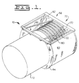
- a heat exchanger or recuperator 10 is attached to an engine 12.
- the engine 12 in this application is a gas turbine engine including an air intake system 14, only partially shown, having a recipient fluid, designated by the arrow 16.
- the engine 12 further includes an exhaust system 18, only partially shown, having a donor fluid, designated by the arrow 20.
- the temperature range of the recipient fluid 16 is lower than the temperature range of the donor fluid 20.
- the heat exchanger 10 could be used with any device having the recipient fluid 16 and the donor fluid 20 and in which heat transfer is desirable.
- the heat exchanger 10 includes a generally circular shaped core 22 being made of many pieces.
- the core 22 has a pair of ends 24 and 26, an inner portion 27 and an outer portion 28.
- the reservoir 52 is positioned in fluid communication with the end 24.
- a housing 56 which in this application is a part of the heat exchanger 10 but as an alternative could be separate therefrom, partially surrounds the core 22.
- the housing 56 includes a generally cylindrical wrapper plate 60, an end plate 62 and a mounting adapter 64 for attaching to the engine 12 in a conventional manner.
- the mounting adapter 64 could be a part of the engine 12.
- a plurality of tie bolts 66 interconnect the end plate 62 and the mounting plate 64 adding further rigidity to the housing 56.
- the air intake system 14, as partially shown in Figs. 2 and 3, of the engine 12 further includes a plurality of inlet ports 80 and a plurality of outlet ports 82 therein through which the recipient fluid 16 passes.
- the inlet and outlet ports 80,82 are arranged in a generally circular band 84 (shown in phantom) centered about the central axis 29. Each of the inlet and outlet ports 80,82 are alternately positioned in the band 84.
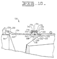
- the means 38 for sealing includes a seal 98 positioned between the end 26 of the core 22 and the end plate 62.
- the sealing means 38 further includes a manifold or an adapter 102.
- the manifold 102 has one end fixedly attached to the mounting adapter 64 or as an alternative could be attached directly to the engine 12. The other end is removably attachable in sealing contact with the core 22. At least a portion of the manifold 102 is interwoven between the plurality of inlet and outlet ports 80,82.
- the manifold 102 includes a generally cylindrical portion 108 having a pair of end portions 110,112.
- the cylindrical portion 108 includes a plurality of hyperbolic sleeve portions 114 which are die formed at the end portion 112 from an integral piece.
- the cylindrical portion 108 could be formed from individual components.
- the cylindrical portion 108 would have a plurality of evenly spaced cutouts therein and the plurality of hyperbolic shaped sleeve portions 114 would be positioned about the cutouts and fixedly connected to the cylindrical portion 108 such as by welding.
- the end portion 112 of the cylindrical portion 108 is fixedly attached to the mounting adapter 64, such as by welding.
- the end portion 110 is removably attached to the core 22 in a tongue and groove configuration.
- a pair of concentric cylinder members 116 are fixedly attached to the core 22.
- the pair of cylinder members 116 have a predetermined space or gap 117 therebetween so that the end portion 110 of the cylindrical portion 108 sealingly fits therein.
- the members 116 each have an end portion 118 which is bent or formed to provide a ramp so that the tongue 110 can easily be positioned into the groove 117.
- the space or gap 117 should be between about .20 mm and .30 mm smaller than the thickness of the tongue 110. In this specific application the space or gap 117 is about .25 mm smaller than the thickness of the tongue 110.
- the depth of the engagement of the tongue 110 into the groove 117 does not substantially effect the sealing characteristics as greatly as does the relationship of the interference fit.
- the tongue 110 is inserted into the groove to an approximate depth of 12 mm.
- the tongue 110 and groove 117 combination also centers and positions the core 22.
- the tongue 110 which is also the end could be a portion of the core 22 and the pair of concentric cylinder members 116 could be a part of the cylindrical portion 108.
- a seal 119 can be positioned in the space 117 between the pair of members 116 so that seal 119 contacts each of the pair of concentric cylinder members 116 and the end or tongue 110, thus, prevents leakage though the joint.
- the manifold 102 could be fixedly attached to the core 22 and removably attached to the mounting adapter 64 or the engine 12.
- the manifold 102 would include a seal carrier 120 having a generally channel shape including a base portion 122 fixedly attached to the hyperbolic shaped sleeve portions 114 and the remainder of the end 112.
- the seal carrier 120 further includes a pair of arms 124 extending from the base portion 122.
- the means 38 for sealing the recipient fluid 16 further includes an apparatus 126 for surrounding the plurality of inlet and outlet ports 80,82.
- the apparatus 126 also seals between the exhaust system 18 and the intake system 14.
- the apparatus 126 includes an inner sealing portion 128 and an outer sealing portion 130.
- the inner sealing portion 128 and the outer sealing portion 130 act as means 131 for biasing the core 22 in sealing contact with the seal 98 between the core 22 and the end plate 62.
- the inner sealing portion 128 includes an inner annular guiding member 132 centered about the axis 29 and is attached to the mounting plate 64.
- An inner mounting flange 134 has a plurality of holes 136 therein and is fixedly attached to the member 132.
- An inner generally cylindrical member 138 which is a part of the inner sealing portion 128 is attached to the core 22. Further included in the sealing portion 128 is an inner annular guiding portion 140 attached to the generally cylindrical member 138. An inner annular fastening ring 142 is attached to the inner annular guiding portion 140 and has a plurality of holes 144 therein corresponding to the holes 136 in the inner mounting flange 134. An inner seal 146 is sealingly removably positioned between the inner mounting flange 134 and the inner annular fastener ring 142 by a plurality of fastener or bolt and nut combinations 148.
- the outer sealing portion includes an outer annular guiding member 150 external of the inner annular guiding member 132. The member 150 is attached to the mounting plate 64.
- An outer mounting flange 152 is attached to the outer annular guiding member 132 and has a plurality of holes 156 therein.
- the outer portion 132 further includes an outer generally cylindrical member 158 attached to the core 22.
- An outer annular guiding member 160 is attached to the outer generally cylindrical member 158.
- An outer annular fastening ring 162 which is a part of the outer portion 132 is attached to the outer annular fastening ring 162 and has a plurality of holes 164 therein corresponding to the holes 156 in the outer mounting flange 152.
- An outer seal 166 is sealingly removably positioned between the outer mounting flange 152 and the outer annular fastener ring 162 by a plurality of fastener or bolt and nut combinations 168.
- the inner sealing portion 128 would include a generally cylindrical convoluted ring 180 having one end fixedly attached to the mounting adapter 64, such as by welding.
- the ring 180 would be centered about the axis 29 and would be positioned radially inward of the inlet and outlet ports 80,82.
- the other end of the ring 180 would have a cylindrical abutting member 181 attached thereto.
- the abutting member 181 has a generally "L" shaped cross-section including a long leg 182 and a short leg 183 having a sealing surface 184 thereon.
- the long leg 182 is attached to the ring 180 and the sealing surface 184 is in sealing contact with a continuous cylindrical seal 185.
- the seal 185 is made of laminated graphite but could be of other materials and designs such as spun fiber, centered metal or copper.
- the seal 185 is positioned and retained in a holder 186 which is fixedly attached to the core 22.
- the holder 186 includes a body 187 having one end attached to the core 22, such as by welding and the other end has a portion thereof having a sealing surface 188 thereon.
- a cylindrical member 189 is attached at the end having the portion thereof having the sealing surface 188 thereon.
- a conical shaped cylindrical guiding member 190 is attached to the the cylindrical member 189 and guides the core 22 and the seal 185 into radial position so that the seal 185 and the sealing surface 184 are in sealing contact with each other.
- the inner sealing portion 128 would include a first generally cylindrical member 191 having one end fixedly attached to the mounting adapter 64, such as by welding.
- the first cylindrical member 191 would have a lip portion 192 attached or formed at the other end.
- the lip portion 192 is formed radially outward of the first cylindrical member 191, but as an alternative could be attached or formed radially inward of the first cylindrical member 191.
- a second generally cylindrical member 193 having one fixedly attached to the core 22, such as by welding is also included in the inner sealing portion 128.
- the second generally cylindrical member 193 would have a lip portion 194 attached or formed at the other end.
- the lip portion 194 is formed radially inward of the second cylindrical member 193 so that when the first and the second generally cylindrical members 191,193 are axially positioned relative to each other, a pocket 195 is formed and a seal 196 is disposed therein.
- the lip portion 294 of the second generally cylindrical member 193 could be formed radially outward to conform to the lip portion 192 being formed radially inward on the first generally cylindrical member 193.
- the seal 196 can be made of a spun fiber, powered metal or carbon material.
- a conical shaped cylindrical guiding member 197 is attached to the lip portion 194 and guides the core 22 and the seal 196 into radial sealing position with the lip portion 192.
- the outer sealing portion 130 would be adapted to use a band type clamp.
- the outer sealing portion 130 would include a generally cylindrical ring 200 having an inner surface 202, an outer surface 204 and an end 206 fixedly attached to the mounting adapter 64, such as by welding.
- an end portion 208 would be configured to conform a portion of a band type clamp.
- the end 208 would include a raised portion 210 having a sealing surface 212 extending outwardly a preestablished distance from the inner surface 202 and being substantially perpendicular to the inner surface 202.
- a top surface 214 extends axially away from the surface 212 a preestablished distance and substantially perpendicular to the sealing surface 212.
- the compressor section of the conventional gas turbine engine 12 compresses atmospheric air or recipient fluid 16 prior to passing through the heat recipient passages 32 of the heat exchanger 10. Exhaust gases or donor fluid 20 from the combustion in the engine 12 pass through the heat donor passages 40 of the heat exchanger 10 and thermally heat the recipient fluid 16 in the heat exchanger 10 prior to reentering the engine 12. The recipient fluid is then mixed with fuel, combusted and exhausted as the donor fluid 20. Thus, during operation of the engine 12 a continuous cycle occurs.
- the cyclic operation of the engine 12 causes the exhaust gas temperature to increase and decrease. Furthermore, the intake air and the exhaust gas volume and pressure vary depending on the cyclic operation. Thus, thermal stress and structural integrity of the heat exchanger and the sealing components are stressed to the ultimate.
- the core 22 is removably attached to the engine 12.
- the end 112 of the cylindrical portion 108 is fixedly attached to the mounting adapter 64.
- the pair of concentric cylinders 116 are positioned about the tongue or end 110.
- the end 26 of the core 22 is positioned with the seal 98 in contact with the end plate 62.
- the end 110 is slidably in sealing contact with the pair of concentric cylinders 116.
- the core 22 is free to move axially between the cylindrical portion 108 and the end plate 62.
- the plurality of holes 144 in the inner annular fastening ring 142 are aligned with the plurality of holes 136 in the inner mounting flange 134, and the seal 146 is positioned between the inner annular fastening ring 142 and the inner mounting flange 134.
- the ring 142, the flange 134 and the seal 146 are fastened together by the plurality of fasteners 148.
- the plurality of holes 164 in the outer annular fastening ring 162 are aligned with the plurality of holes 156 in the outer mounting flange 152, and the seal 166 is positioned between the outer annular fastening ring 162 and the outer mounting flange 152.
- the heat exchanger 10 is assembled in functional operating relationship to the engine 12.
- the exhaust gases or donor fluid 20 exit the engine 12, enter the donor passage 34 of the heat exchanger 10 and the individual primary surface pleated sheets are heated by the hot exhaust 20.
- compressed air or recipient fluid 16 exits the plurality of outlet ports 82, enters the circular reservoir 46 and is directed to the plurality of recipient passages 32.
- the recipient fluid 16 is heated in the recipient passages 32 and is directed into the circular reservoir 52. From the circular reservoir 52 the heated recipient fluid 16 reenters the engine 12 through the plurality of inlet ports 80.
- the recipient fluid 16 is mixed with fuel and combusted in the engine 12 increasing the efficiency of the engine 12.
- the tongue 110 and groove 117 which is biasedly positioned between the core 22 and the engine 12 and the portion of the sealing means 38 adapted to seal the intake system 14 from the exhaust system 18, insures that the recipient fluid 16 passes through the heat recipient passage 32 of the heat exchanger 10. Furthermore, the portion of the means 38 adapted to seal the exhaust system 18 insures that the donor fluid 20 is circulate through the heat exchanger 10.
- the biasing means 131 further insures that the seal 98 is in sealing contact between the core 22 and the end plate 62.
- the tongue 110 and groove 117 further insures that the cooler recipient fluid 16 is separated from the heated recipient fluid 16.
- the construction of the tongue 110 and groove 117 being an interference fit accomplishes the sealing since the tongue 110 is in frictional engagement with each of the cylindrical member 116.
Landscapes
- Engineering & Computer Science (AREA)
- Physics & Mathematics (AREA)
- Thermal Sciences (AREA)
- Mechanical Engineering (AREA)
- General Engineering & Computer Science (AREA)
- Heat-Exchange Devices With Radiators And Conduit Assemblies (AREA)
Claims (24)
- Wärmetauscher (10),der geeignet ist zur Verwendung in einem Motor (12), der ein Auslaß- oder Abgassystem (18) zur Abgabe eines Abgabeströmungsmittels (20) an den Wärmetauscher und ein Lufteinlaßsystem (14) zur Aufnahme eines Aufnahmeströmungsmittels (16) von dem Wärmetauscher umfaßt, wobei das Lufteinlaßsystem (14) eine Vielzahl von Einlaßanschlüssen (80) für das Aufnahmeströmungsmittel (16) und eine Vielzahl von Auslaßanschlüssen (82) für das Aufnahmeströmungsmittel (16) umfaßt, wobei der Wärmetauscher (10) bei der Verwendung in Strömungsmittelverbindung mit dem Auslaß- bzw. Abgassystem (18) und dem Lufteinlaßsystem (14) angeordnet ist, und einen Kern (22) mit einer Vielzahl von Wärmeaufnahmedurchlässen (32) und einer Vielzahl von Wärmeabgabedurchlässen (34) darin, wobei der Kern (22) allgemein kreisförmig ist und eine Mittelachse (29) besitzt und, wenn er eingebaut ist, entfernbar bzw. lösbar an dem Motor (12) befestigt ist, wodurch er Mittel (44) zum Verteilen des Aufnahmeströmungsmittels (16) in dem Kern (22) und Mittel (50) zum Sammeln des Aufnahmeströmungsmittels (16) nach dem Hindurchlaufen durch den Kern (22) definiert, und ein Gehäuse (56) umfaßt, das den Kern (22) umgibt; gekennzeichnet durch Mittel (38) zum Abdichten, die eine Sammelleitung (102) umfassen, die zwischen dem Gehäuse (56) und dem Kern (22) angeordnet ist und ein Ende (110, 112) besitzt, das an entweder dem Kern (22) oder dem Gehäuse (56) fest angebracht ist, und wobei das andere Ende (110, 112) in abdichtendem Kontakt mit entweder dem Gehäuse (56) oder dem Kern (22) befestigt werden kann, wenn sie eingebaut ist, wobei die Vielzahl der Einlaß- und Auslaßanschlüsse (80, 82) bei der Verwendung in einem allgemein kreisförmigen Band oder Bereich (84) angeordnet ist, das um die Mittelachse (29) zentriert ist und wobei die Einlaßanschlüsse (80) und die Auslaßanschlüsse (82) abwechselnd in dem Band bzw. Bereich (84) positioniert sind, wobei zumindest ein Teil der Sammelleitung (102) bei der Verwendung zwischen der Vielzahl von Einlaß- und Auslaßanschlüssen (80, 82) verwoben bzw. verflochten ist, wobei die Mittel zum Abdichten zwischen den Mitteln zum Verteilen (44) und den Mitteln zum Sammeln (50) angeordnet sind, so daß das Aufnahmeströmungsmittel (16) vor dem Eintritt in den Kern (22) und nach dem Hindurchlaufen durch den Kern (22) bei der Verwendung voneinander getrennt ist.
- Wärmetauscher gemäß Anspruch 1, wobei die Mittel (38) zum Abdichten eine Zunge (110) und eine Nut (117) umfassen, welche zwischen einem Paar von allgemein konzentrischen Zylindergliedern (116) gebildet ist, wobei entweder die Zunge (110) oder die Glieder (116) fest an dem Kern (22) angebracht ist bzw. sind, und wobei entweder die Glieder (116) oder die Zunge (110) an dem Motor (12) befestigt sind bzw. ist, und zwar in installiertem Zustand, und wobei die Zunge (110) und die Nut (117) ferner das Aufnahmeströmungsmittel vor dem Eintritt in den Kern (22) und nach dem Hindurchlaufen durch den Kern (22) abdichten.
- Wärmetauscher gemäß Anspruch 2, wobei die Zunge (110) an dem Kern (22) befestigt ist.
- Wärmetauscher gemäß Anspruch 2 oder Anspruch 3, wobei die Mittel (38) zum Abdichten ferner eine Dichtung (118) umfassen, die in der Nut (117) angeordnet ist.
- Wärmetauscher gemäß Anspruch 4, wobei die Dichtung (118) in abdichtendem Kontakt mit sowohl den allgemein zylindrischen Gliedern (116) als auch der Zunge (110) steht.
- Wärmetauscher gemäß einem der Ansprüche 2 bis 5, wobei die Zunge (110) in einer Kontaktbeziehung mit mindestens einem der allgemein zylindrischen Glieder (116) steht.
- Wärmetauscher gemäß Anspruch 6, wobei die Zunge (110) in Kontaktbeziehung mit jedem der allgemein zylindrischen Glieder (116) steht.
- Wärmetauscher gemäß einem der vorhergehenden Ansprüche, wobei die Mittel (38) zum Abdichten ferner eine Vorrichtung (126) umfassen zum Umgeben der Vielzahl von Einlaß- und Auslaßanschlüssen (80, 82).
- Wärmetauscher gemäß Anspruch 8, wobei die Vorrichtung (126) einen inneren Abdichtteil (128) und einen äußeren Abdichtteil (130) umfaßt.
- Wärmetauscher gemäß Anspruch 9, wobei der innere Abdichtteil (128) und der äußere Abdichtteil (130) den Kern (22) entfernbar bzw. lösbar an dem Gehäuse (56) befestigen unter Verwendung einer Vielzahl von Befestigungsmitteln (148, 168).
- Wärmetauscher gemäß Anspruch 9, wobei der innere Abdichtteil (128) und der äußere Abdichtteil (130) den Kern (22) in vorspannender Weise an dem Gehäuse (56) befestigen.
- Wärmetauscher gemäß Anspruch 11, wobei der innere Abdichtteil (128) einen gewundenen bzw. eingedrehten Ring (180) umfaßt, der an entweder dem Kern (22) oder dem Befestigungsadapter (64) fest angebracht ist, und ein anstoßendes Glied (181) umfaßt, das an entweder dem Befestigungsadapter (64) oder dem Kern (22) befestigt ist.
- Wärmetauscher gemäß Anspruch 12, wobei der innere Abdichtteil (128) ferner eine Abdichtoberfläche (184, 188) umfaßt, die an sowohl dem gewundenen Ring (180) als auch dem anstoßenden Glied (181) befestigt ist.
- Wärmetauscher gemäß Anspruch 13, wobei der innere Abdichtteil (128) ferner eine Dichtung (185) umfaßt, die in abdichtender Beziehung mit den Dichtoberflächen (184, 188) positioniert ist.
- Wärmetauscher gemäß Anspruch 9, wobei der innere Abdichtteil (128) ein erstes und zweites zylindrisches Glied (191, 193) umfaßt, die an entweder dem Kern (22) oder dem Befestigungsadapter (64) befestigt sind, wobei jedes der ersten und zweiten zylindrischen Glieder (191, 193) einen Lippenteil (192, 194) besitzt, der daran befestigt ist.
- Wärmetauscher gemäß Anspruch 15, wobei die Lippenteile (192, 194) eine Tasche (195) dazwischen bilden, wenn sie axial relativ zueinander positioniert sind.
- Wärmetauscher gemäß Anspruch 16, wobei eine Dichtung (196) in der Tasche (195) positioniert ist.
- Wärmetauscher gemäß einem der Ansprüche 9 bis 17, wobei der äußere Teil (130) ein Paar von allgemein zylindrischen Ringen (200, 220) umfaßt, die an entweder dem Kern (22) oder dem Befestigungsadapter (64) fest angebracht sind, wobei jeder der allgemein zylindrischen Ringe (200, 220) einen Endteil (208, 228) umfaßt, der jeweils eine Keiloberfläche (216, 236) und eine Klemme (240) besitzt, die die Endteile (208, 228) in abdichtender Beziehung entfernbar bzw. lösbar befestigt.
- Wärmetauscher gemäß Anspruch 18, wobei der äußere Teil (130) ferner eine Abdichtoberfläche (212, 232) umfaßt, die an jedem der Endteile (208, 228) befestigt ist.
- Wärmetauscher gemäß Anspruch 19, wobei eine Dichtung (246) zwischen der Dichtungsoberfläche (212, 232) positioniert ist.
- Wärmetauscher gemäß einem der vorhergehenden Ansprüche, wobei die Sammelleitung (102) ferner eine kontinuierliche Dichtung (170) umfaßt, die zwischen der Vielzahl von Einlaß- und Auslaßanschlüssen (80, 82) verwoben bzw. verflochten ist.
- Wärmetauscher gemäß Anspruch 21, wobei der Teil der Sammelleitung (102), der zwischen der Vielzahl von Einlaß- und Auslaßanschlüssen (80, 82) verwoben bzw. verflochten ist, an das Gehäuse (56) geschweißt ist.
- Wärmetauscher gemäß Anspruch 2 oder Anspruch 22, wobei die Sammelleitung (102) ferner einen zylindrischen Teil (108) umfaßt mit einer Vielzahl von bogenförmigen Teilen (174), die einen gemeinsamen Radius besitzen, und mit einer Vielzahl von hyperbolischen Teilen (172), die dazwischen verbunden sind.
- Wärmetauscher gemäß Anspruch 23, wobei die bogenförmige Teile (174) und die hyperbolischen Teile (172) gleichmäßig dazwischen beabstandet sind.
Applications Claiming Priority (3)
| Application Number | Priority Date | Filing Date | Title |
|---|---|---|---|
| US530954 | 1990-05-29 | ||
| US07/530,954 US5065816A (en) | 1990-05-29 | 1990-05-29 | Sealing system for a circular heat exchanger |
| PCT/US1990/004687 WO1991019152A1 (en) | 1990-05-29 | 1990-08-20 | A sealing system for a circular heat exchanger |
Publications (2)
| Publication Number | Publication Date |
|---|---|
| EP0530183A1 EP0530183A1 (de) | 1993-03-10 |
| EP0530183B1 true EP0530183B1 (de) | 1995-02-01 |
Family
ID=24115673
Family Applications (1)
| Application Number | Title | Priority Date | Filing Date |
|---|---|---|---|
| EP90913624A Expired - Lifetime EP0530183B1 (de) | 1990-05-29 | 1990-08-20 | Dichtung für kreisförmigen wärmetauscher |
Country Status (6)
| Country | Link |
|---|---|
| US (1) | US5065816A (de) |
| EP (1) | EP0530183B1 (de) |
| JP (1) | JP3025302B2 (de) |
| AU (1) | AU6352090A (de) |
| CA (1) | CA2081101A1 (de) |
| WO (1) | WO1991019152A1 (de) |
Families Citing this family (15)
| Publication number | Priority date | Publication date | Assignee | Title |
|---|---|---|---|---|
| DE4118777C2 (de) * | 1991-06-07 | 2002-04-18 | Mtu Aero Engines Gmbh | Gasturbinentriebwerk mit Wärmetauscher |
| US5497615A (en) * | 1994-03-21 | 1996-03-12 | Noe; James C. | Gas turbine generator set |
| JPH0942865A (ja) * | 1995-07-28 | 1997-02-14 | Honda Motor Co Ltd | 熱交換器 |
| JPH10122768A (ja) * | 1996-10-17 | 1998-05-15 | Honda Motor Co Ltd | 熱交換器 |
| JPH10206067A (ja) * | 1997-01-27 | 1998-08-07 | Honda Motor Co Ltd | 熱交換器の支持構造 |
| US6357113B1 (en) | 1999-11-04 | 2002-03-19 | Williams International Co., L.L.C. | Method of manufacture of a gas turbine engine recuperator |
| US6438936B1 (en) | 2000-05-16 | 2002-08-27 | Elliott Energy Systems, Inc. | Recuperator for use with turbine/turbo-alternator |
| US6474408B1 (en) * | 2000-08-31 | 2002-11-05 | Honeywell International Inc. | Heat exchanger with bypass seal allowing differential thermal expansion |
| US6918598B2 (en) * | 2002-04-02 | 2005-07-19 | Honeywell International, Inc. | Hot air seal |
| US7147050B2 (en) * | 2003-10-28 | 2006-12-12 | Capstone Turbine Corporation | Recuperator construction for a gas turbine engine |
| US7065873B2 (en) * | 2003-10-28 | 2006-06-27 | Capstone Turbine Corporation | Recuperator assembly and procedures |
| US7124572B2 (en) * | 2004-09-14 | 2006-10-24 | Honeywell International, Inc. | Recuperator and turbine support adapter for recuperated gas turbine engines |
| AU2010340372B2 (en) | 2010-01-08 | 2015-02-12 | Halliburton Energy Services, Inc. | Alignment of BOP stack |
| US10151247B2 (en) * | 2016-03-18 | 2018-12-11 | United Technologies Corporation | Heat exchanger suspension system with pipe-to-linkage spring rate ratio |
| US12487037B2 (en) * | 2022-08-02 | 2025-12-02 | Hamilton Sundstrand Corporation | Flexural support for heat exchanger cores |
Family Cites Families (23)
| Publication number | Priority date | Publication date | Assignee | Title |
|---|---|---|---|---|
| US2594761A (en) * | 1947-01-02 | 1952-04-29 | Rolls Royce | Heat exchanger |
| US2795930A (en) * | 1951-12-06 | 1957-06-18 | A V Roe Canada Ltd | Joint construction for combustion chamber casings |
| GB715491A (en) * | 1951-12-19 | 1954-09-15 | Ici Ltd | Improvements in or relating to plate type heat exchangers |
| FR1211918A (fr) * | 1957-12-23 | 1960-03-18 | Foster Wheeler Ltd | échangeurs de chaleur perfectionnés |
| US3118278A (en) * | 1959-06-26 | 1964-01-21 | Gas turbine power plant | |
| US3224502A (en) * | 1963-05-29 | 1965-12-21 | United Aircraft Corp | Finned envelope heat exchanger |
| US3255818A (en) * | 1964-03-09 | 1966-06-14 | Gen Motors Corp | Involute plate heat exchanger |
| US3285326A (en) * | 1964-09-18 | 1966-11-15 | Int Harvester Co | Recuperative type heat exchanger |
| DE1426325B2 (de) * | 1964-12-12 | 1970-09-17 | Daimler-Benz AG, 7OOO Stuttgart | Gasturbinentriebwerk |
| US3507115A (en) * | 1967-07-28 | 1970-04-21 | Int Harvester Co | Recuperative heat exchanger for gas turbines |
| US3476174A (en) * | 1967-12-29 | 1969-11-04 | Gen Motors Corp | Regenerator matrix |
| US3759323A (en) * | 1971-11-18 | 1973-09-18 | Caterpillar Tractor Co | C-flow stacked plate heat exchanger |
| US3818984A (en) * | 1972-01-31 | 1974-06-25 | Nippon Denso Co | Heat exchanger |
| US3889744A (en) * | 1972-04-20 | 1975-06-17 | Owens Illinois Inc | Recuperator structures and method of making same |
| US3785435A (en) * | 1972-11-15 | 1974-01-15 | Avco Corp | Thermal damper for plate type heat exchangers |
| US4005573A (en) * | 1975-10-01 | 1977-02-01 | General Motors Corporation | Recuperative mounting |
| GB1539035A (en) * | 1976-04-22 | 1979-01-24 | Rolls Royce | Combustion chambers for gas turbine engines |
| US4098330A (en) * | 1976-07-23 | 1978-07-04 | General Motors Corporation | Annular metal recuperator |
| US4072327A (en) * | 1976-10-01 | 1978-02-07 | Caterpillar Tractor Co. | Slip joint between a gas turbine engine and a heat exchanger |
| FR2439970B1 (fr) * | 1978-10-26 | 1986-05-09 | Garrett Corp | Echangeur thermique |
| US4413470A (en) * | 1981-03-05 | 1983-11-08 | Electric Power Research Institute, Inc. | Catalytic combustion system for a stationary combustion turbine having a transition duct mounted catalytic element |
| US4474000A (en) * | 1982-11-12 | 1984-10-02 | Williams International Corporation | Recuperated turbine engine |
| US4582126A (en) * | 1984-05-01 | 1986-04-15 | Mechanical Technology Incorporated | Heat exchanger with ceramic elements |
-
1990
- 1990-05-29 US US07/530,954 patent/US5065816A/en not_active Expired - Lifetime
- 1990-08-20 WO PCT/US1990/004687 patent/WO1991019152A1/en not_active Ceased
- 1990-08-20 JP JP2512733A patent/JP3025302B2/ja not_active Expired - Fee Related
- 1990-08-20 EP EP90913624A patent/EP0530183B1/de not_active Expired - Lifetime
- 1990-08-20 AU AU63520/90A patent/AU6352090A/en not_active Abandoned
- 1990-08-20 CA CA002081101A patent/CA2081101A1/en not_active Abandoned
Also Published As
| Publication number | Publication date |
|---|---|
| EP0530183A1 (de) | 1993-03-10 |
| JPH05506917A (ja) | 1993-10-07 |
| US5065816A (en) | 1991-11-19 |
| AU6352090A (en) | 1991-12-31 |
| WO1991019152A1 (en) | 1991-12-12 |
| JP3025302B2 (ja) | 2000-03-27 |
| CA2081101A1 (en) | 1991-11-30 |
Similar Documents
| Publication | Publication Date | Title |
|---|---|---|
| EP0530181B1 (de) | Kreisförmiger wärmetauscher | |
| EP0530183B1 (de) | Dichtung für kreisförmigen wärmetauscher | |
| US5081834A (en) | Circular heat exchanger having uniform cross-sectional area throughout the passages therein | |
| US4229868A (en) | Apparatus for reinforcement of thin plate, high pressure fluid heat exchangers | |
| US4291752A (en) | Heat exchanger core attachment and sealing apparatus and method | |
| US8028410B2 (en) | Gas turbine regenerator apparatus and method of manufacture | |
| US4582126A (en) | Heat exchanger with ceramic elements | |
| US3424240A (en) | Corrugated stacked-plate heat exchanger | |
| EP0530324B1 (de) | Thermisches rückhaltesystem für einen kreislaufwärmetauscher | |
| US4917181A (en) | Segmented annular recuperator and method | |
| US20040003916A1 (en) | Unit cell U-plate-fin crossflow heat exchanger | |
| US4367789A (en) | Industrial cooling exchanger used for cooling air or other gases | |
| WO1999023435A1 (en) | Improved method for making a recuperator cell |
Legal Events
| Date | Code | Title | Description |
|---|---|---|---|
| PUAI | Public reference made under article 153(3) epc to a published international application that has entered the european phase |
Free format text: ORIGINAL CODE: 0009012 |
|
| 17P | Request for examination filed |
Effective date: 19921028 |
|
| AK | Designated contracting states |
Kind code of ref document: A1 Designated state(s): AT BE CH DE DK ES FR GB IT LI LU NL SE |
|
| RBV | Designated contracting states (corrected) |
Designated state(s): GB |
|
| REG | Reference to a national code |
Ref country code: DE Ref legal event code: 8566 |
|
| 17Q | First examination report despatched |
Effective date: 19931006 |
|
| GRAA | (expected) grant |
Free format text: ORIGINAL CODE: 0009210 |
|
| AK | Designated contracting states |
Kind code of ref document: B1 Designated state(s): GB |
|
| PLBE | No opposition filed within time limit |
Free format text: ORIGINAL CODE: 0009261 |
|
| STAA | Information on the status of an ep patent application or granted ep patent |
Free format text: STATUS: NO OPPOSITION FILED WITHIN TIME LIMIT |
|
| 26N | No opposition filed | ||
| PGFP | Annual fee paid to national office [announced via postgrant information from national office to epo] |
Ref country code: GB Payment date: 19990601 Year of fee payment: 10 |
|
| PG25 | Lapsed in a contracting state [announced via postgrant information from national office to epo] |
Ref country code: GB Free format text: LAPSE BECAUSE OF NON-PAYMENT OF DUE FEES Effective date: 20000820 |
|
| GBPC | Gb: european patent ceased through non-payment of renewal fee |
Effective date: 20000820 |