EP0532492A1 - Pflug mit einer Antriebseinrichtung - Google Patents
Pflug mit einer Antriebseinrichtung Download PDFInfo
- Publication number
- EP0532492A1 EP0532492A1 EP92890192A EP92890192A EP0532492A1 EP 0532492 A1 EP0532492 A1 EP 0532492A1 EP 92890192 A EP92890192 A EP 92890192A EP 92890192 A EP92890192 A EP 92890192A EP 0532492 A1 EP0532492 A1 EP 0532492A1
- Authority
- EP
- European Patent Office
- Prior art keywords
- plow
- drive shaft
- tractor
- shaft
- drive
- Prior art date
- Legal status (The legal status is an assumption and is not a legal conclusion. Google has not performed a legal analysis and makes no representation as to the accuracy of the status listed.)
- Granted
Links
Images


Classifications
-
- A—HUMAN NECESSITIES
- A01—AGRICULTURE; FORESTRY; ANIMAL HUSBANDRY; HUNTING; TRAPPING; FISHING
- A01B—SOIL WORKING IN AGRICULTURE OR FORESTRY; PARTS, DETAILS, OR ACCESSORIES OF AGRICULTURAL MACHINES OR IMPLEMENTS, IN GENERAL
- A01B61/00—Devices for, or parts of, agricultural machines or implements for preventing overstrain
- A01B61/02—Devices for, or parts of, agricultural machines or implements for preventing overstrain of the coupling devices between tractor and machine
- A01B61/025—Devices for, or parts of, agricultural machines or implements for preventing overstrain of the coupling devices between tractor and machine the driving connections
-
- A—HUMAN NECESSITIES
- A01—AGRICULTURE; FORESTRY; ANIMAL HUSBANDRY; HUNTING; TRAPPING; FISHING
- A01B—SOIL WORKING IN AGRICULTURE OR FORESTRY; PARTS, DETAILS, OR ACCESSORIES OF AGRICULTURAL MACHINES OR IMPLEMENTS, IN GENERAL
- A01B17/00—Ploughs with special additional arrangements, e.g. means for putting manure under the soil, clod-crushers
- A01B17/004—Clod-crushers
- A01B17/006—Clod-crushers with driven tools
Definitions
- the invention relates to a drive device for plows, in particular rotary plows, with at least one ploughshare which is connected to a grinder connected to a plow hitch or the like a drive shaft can be driven.
- the invention has for its object to solve these problems and achieves this in that, according to the invention, the transmission, countershaft or the like. Is detachably attached between the trestle and the tractor, the output shaft of the transmission being lower than the plow headstock and with the drive shaft for the crushing tool or the like preferably via a joint. is connected in terms of drive. This advantageously eliminates both of the above-mentioned disadvantages of conventional designs.
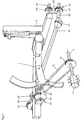
- the plowshares - in the present exemplary embodiment three double plowshares - are designated by 3, which or the like are connected via a shaft 1 to a plow attachment bracket 2 or the like connected to the tractor 21 in a manner not shown. are rotatably connected.
- Each of the plowshares 3 has two opposite plow bodies 20 or mouldboards, which are brought into working position alternately along vertical guides 11.
- Each ploughshare 3 of the plow body 20 is assigned a comminution tool 4, which is not shown in FIG. 1 for the sake of clarity.
- the comminution tools 4 serve to comminute and distribute the earth thrown up by the plow bodies 20 or mouldboards and connect to the plow body 20 which has been lowered in each case.
- the crushing tools 4 are formed in the illustrated embodiment as tine wheels, which sit on a common, drivable shaft 6, which is from a tractor PTO 40 via a gear 44, which can be a forward and reverse gear, further via a drive shaft 42 and another gear 33 is driven.
- the tractor-side gear 44 is detachably connected to the PTO shaft 40 of the tractor 21, so that it can be attached to or removed from the tractor as required.
- the gear 44 is also designed so that it extends from the PTO 40 down below the plow headstock 2, where the output shaft 48 of the tractor-side gear 44 comes to rest.
- this gear 44 is made up of two sprockets 43, 43 'and a chain 45 connecting them, the upper sprocket 43 being connected to the PTO shaft 40 of the tractor 21 and the lower sprocket 43' being connected to the output shaft 48.
- the gear 44 can also include a reduction gear and the like from gears, sprockets or the like. in a suitable combination.
- the output shaft 48 of the tractor-side transmission 44 drives a drive shaft 42 which runs obliquely upwards via a joint 47, which in turn drives a transmission 46 via a joint 49, which has a chain wheel 34 and 35 on each side of the spindle 1.
- the two sprockets 34, 35 are connected by a chain 50, as shown in FIGS. 2 and 3, which represent the drive device for the shredding tools 4 on a larger scale and in perspective.
- One of the chain wheels of the gear 46 attached to the spindle 1 is connected in terms of drive to a further chain wheel 36 which drives the shaft 6 of the comminution tools 4 via a chain 51 and a further chain wheel 52.
- the shaft 6 is driven in the direction that the crushing tools 4 transport the crumbled parts of the earth away from the plowshares 3.
- FIG. 3 which shows a detail of the device according to FIG. 2, chains 50 and 51 are protected according to an advantageous embodiment by protective housings against mechanical damage, penetration of moisture and dust, etc., in order to avoid operational disturbances associated therewith.
- the gear 46 with the sprockets 34, 35, 36 is by a housing 33 attached to the spindle 1 and the chain 51 and the sprocket 52 on the shaft 6 of the shredding tools 4 by an elongated housing 53 which extends to the spindle 1 or to Housing 33 is sufficient, protected.
- the design of the shredding tools 4 is not limited to the design shown as tine wheels, but depending on the nature of the ground or other criteria, tines of any shape, plates, sheets, brushes etc. are possible.
- the drive connection of the gearwheels within the gearbox or the connection between the gearbox 46 and the Shaft 6 of the crushing tools 4 are not only chains, but also toothed belts or the like, for example. executable.
- Direct gear wheel connections are also possible for the drive connection within the gearbox. In the case of rotary plows, the plow is rotated independently of the PTO shaft, which is only used for the rotary drive of the shredding tool.
- the shifting of the forward and return gear 44 on the tractor side is carried out manually or is actuated automatically when the plow is turned. Due to the arrangement of the drive shaft 42 underneath the headstock 2, the plow can only be turned without any problems.
- the construction according to the invention is not only applicable for reversible plows, but also for bed plows or other plows, in which case the gearbox 44 on the actuator side need not be a forward and a downward gear, but only an ordinary one-way gearbox, as is generally required in In this case, a reversing gear is not necessary.
Landscapes
- Life Sciences & Earth Sciences (AREA)
- Engineering & Computer Science (AREA)
- Mechanical Engineering (AREA)
- Soil Sciences (AREA)
- Environmental Sciences (AREA)
- Soil Working Implements (AREA)
Abstract
Description
- Die Erfindung betrifft eine Antriebseinrichtung für Pflüge, insbesondere Drehpflüge, mit mindestens einer Pflugschar, welche an ein mit einem Pfluganbaubock oder dergl. des Traktors verbundenes Grindel angeschlossen ist, sowie mindestens einem jedem Pflugkörper jeder Pflugschar furchenseitig zugeordneten Zerkleinerungswerkzeug, welches von einer Zapfwelle des Traktors über eine Antriebswelle antreibbar ist.
- Bei den bekannten Antriebseinrichtungen dieser Art, wie beispielsweise in der DE-OS 2156 435 beschrieben, bestand die Schwierigkeit, den Antrieb vom Traktor zur Zapfwelle zu lösen, da für diesen Antrieb der Pfluganbaubock od.dgl. im Wege stand. Bei einem ähnlichen, in der GB-PS 1 023 636 beschriebenen Gerät, bei dem lediglich ein rotierendes Werkzeug am hinteren Ende des Pfluges vorgesehen ist, wird die Antriebswelle, mit mehreren Gelenken versehen, tiefer als der Pfluganbaubock zu einem am hinteren Ende des Pfluges angeordneten Getriebe geführt. Dies bedingt eine hohe Gewichtsbelastung des Pfluges und Schwierigkeiten beim Ausheben des Pfluges.
- Die Erfindung hat zur Aufgabe, diese Probleme zu lösen und erzielt dies dadurch, daß erfindungsgemäß das Getriebe, Vorgelege od. dgl. zwischen Anbaubock und Traktor an diesem lösbar angebracht ist, wobei die Abtriebswelle des Getriebes tiefer als der Pfluganbaubock liegt und mit der Antriebswelle für das Zerkleinerungswerkzeug vorzugsweise über ein Gelenk od.dgl. antriebsmäßig verbunden ist. Damit sind in vorteilhafter Weise beide oben angeführten Nachteile der herkömmlichen Konstruktionen beseitigt.
- Bei Drehpflügen treten im Zusammenhang mit dem Antrieb der Zerkleinerungswerkzeuge Probleme auf, deren Ursache in der Ortsveränderung des Antriebes für die Zerkleinerungswerkzeuge beim Drehen des Pfluges gelegen ist. Bei einer Antriebseinrichtung für Drehpflüge mit jeder Pflugschar furchenseitig zugeordnetem Zerkleinerungswerkzeug, welches über eine Antriebswelle antreibbar ist, wird erfindungsgemäß ein problemloses Drehen des Pfluges ausschließlich dadurch bewirkt, daß die Antriebswelle frei verlaufend - sohin ohne Lagerungen - unterhalb des Anbaubockes angeordnet ist.
- Weitere Merkmale und Vorteile der Erfindung werden anhand der Zeichnung näher erläutert, in welcher ein Ausführungsbeispiel der Antriebseinrichtung für einen Drehpflug dargestellt ist. Es zeigen,
- Fig. 1 eine Rückansicht eines dreischarigen Drehpfluges mit der erfindungsgemäßen Antriebseinrichtung,
- Fig. 2 in schaubildlicher Darstellung die Antriebseinrichtung in größerem Maßstab, und
- Fig. 3 ein Detail der in Fig. 2 dargestellten Einrichtung.
- In der Zeichnung sind mit 3 die Pflugscharen - im vorliegenden Ausführungsbeispiel drei Doppelpflugscharen - bezeichnet, welche über ein Grindel 1 an einem in nicht dargestellter Weise mit dem Traktor 21 verbundenen Pfluganbaubock 2 od.dgl. drehbar verbunden sind. Jede der Pflugscharen 3 besitzt zwei einander gegenüberliegende Pflugkörper 20 bzw. Streichbleche, die entlang von Vertikalführungen 11 wechselweise in Arbeitsstellung gebracht werden. Jeder Pflugschar 3 des Pflugkörpers 20 ist ein Zerkleinerungswerkzeug 4 zugeordnet, welches in Fig. 1 der Übersichtlichkeit halber nicht dargestellt ist. Die Zerkleinerungswerkzeuge 4 dienen zur Zerkleinerung und Verteilung der von den Pflugkörpern 20 bzw. Streichblechen aufgeworfenen Erde und schließen an den jeweils abgesenkten Pflugkörper 20 an. Die Zerkleinerungswerkzeuge 4 sind im dargestellten Ausführungsbeispiel als Zinkenräder ausgebildet, welche auf einer ihnen gemeinsamen, antreibbaren Welle 6 sitzen, die von einer Traktorzapfwelle 40 über ein Getriebe 44, das ein Vor- und Rückganggetriebe sein kann, weiters über eine Antriebswelle 42 und ein weiteres Getriebe 33 angetrieben wird. Das traktorseitige Getriebe 44 ist mit der Zapfwelle 40 des Traktors 21 lösbar verbunden, sodaß es je nach Bedarf an den Traktor angesetzt oder abgenommen werden kann. Das Getriebe 44 ist darüberhinaus so ausgebildet, daß es von der Zapfwelle 40 nach unten unterhalb des Pfluganbaubocks 2 reicht, wo auch die Abtriebswelle 48 des traktorseitigen Getriebes 44 zu liegen kommt. Im vorliegenden Fall ist dieses Getriebe 44 aus zwei Kettenrädern 43, 43′ und einer diese verbindenden Kette 45 aufgebaut, wobei das obere Kettenrad 43 mit der Zapfwelle 40 des Traktors 21 und das untere Kettenrad 43′ mit der Abtriebswelle 48 verbunden ist. Selbstverständlich kann außer der dargestellten und soeben beschriebenen Variante, das Getriebe 44 noch ein Vorgelege umfassen und aus Zahnrädern, Kettenrädern od.dgl. in geeigneter Kombination bestehen.
- Die Abtriebswelle 48 des traktorseitigen Getriebes 44 treibt über ein Gelenk 47 eine schräg nach oben verlaufende Antriebswelle 42 an, die ihrerseits über ein Gelenk 49 ein Getriebe 46 antreibt, welches zu beiden Seiten des Grindels 1 je ein Kettenrad 34 bzw. 35 aufweist. Die beiden Kettenräder 34, 35 sind durch eine Kette 50 verbunden, wie dies die Fig. 2 und 3 zeigen, welche die Antriebseinrichtung für die Zerkleinerungswerkzeuge 4 in größerem Maßstab und perspektivischer Ansicht darstellen. Eines der Kettenräder des am Grindel 1 angebrachten Getriebes 46 ist antriebsmäßig mit einem weiteren Kettenrad 36 verbunden, welches über eine Kette 51 und ein weiteres Kettenrad 52 die Welle 6 der Zerkleinerungswerkzeuge 4 antreibt. Der Antrieb der Welle 6 erfolgt in der Richtung, daß die Zerkleinerungswerkzeuge 4 die zerkrümelten Erdteile von den Pflugscharen 3 wegtransportieren.
- In der ein Detail der Einrichtung nach Fig. 2 darstellenden Fig. 3 sind die Ketten 50 und 51 gemäß einer vorteilhaften Ausführungsform durch Schutzgehäuse gegenüber mechanischen Beschädigungen, Eindringen von Feuchtigkeit und Staub etc. geschützt, um damit verbundene Betriebsstörungen zu vermeiden. Das Getriebe 46 mit den Kettenrädern 34, 35, 36 ist durch ein am Grindel 1 befestigtes Gehäuse 33 und die Kette 51 sowie das Kettenrad 52 auf der Welle 6 der Zerkleinerungswerkzeuge 4 durch ein längliches Gehäuse 53, welches bis zum Grindel 1 bzw. bis zum Gehäuse 33 reicht, geschützt.
- Selbstverständlich ist die Ausbildung der Zerkleinerungswerkzeuge 4 nicht auf die dargestellte Ausbildung als Zinkenräder beschränkt, sondern je nach Bodenbeschaffenheit oder anderen Kriterien sind Zinken beliebiger Ausformung, Platten, Bleche, Bürsten etc. möglich. Auch für die antriebsmßige Verbindung der Getrieberäder innerhalb der Getriebe bzw. die Verbindung zwischen dem Getriebe 46 und der Welle 6 der Zerkleinerungswerkzeuge 4 sind nicht nur Ketten, sondern beispielsweise auch Zahnriemen od.dgl. ausführbar. Auch für die antriebsmäßige Verbindung innerhalb der Getriebe sind direkte Zahnradverbindungen möglich. Bei Drehpflügen erfolgt das Drehen des Pfluges unabhängig von der Zapfwelle, welche nur für den Drehantrieb des Zerkleinerungswerkzeuges genutzt wird. Die Schaltung des traktorseitigen Vor- und Rückganggetriebes 44 erfolgt von Hand aus oder wird automatisch beim Drehen des Pfluges betätigt. Durch die Anordnung der Antriebswelle 42 unterhalb des Anbaubockes 2 frei verlaufend ist ein ausschließlich problemloses Drehen des Pfluges möglich. Allerdings ist die erfindungsgemäße Konstruktion nicht nur für Drehpflüge, sondern auch für Beetpflüge oder andere Pflüge anwendbar, wobei dann das Yaktorseitige Getriebe 44 kein Vor- und Rückganggetriebe sein muß, sondern nur mehr ein gewöhnliches, in einer Richtung arbeitendes Getriebe erforderlich ist, wie überhaupt in diesem Fall ein Drehrichtungsumkehrgetriebe nicht notwendig ist.
Claims (2)
- Antriebseinrichtung für Pflüge, insbesondere Drehpflüge, mit mindestens einer Pflugschar (3), welche an ein mit einem Pfluganbaubock (2) od.dgl. des Traktors (21) verbundenes Grindel (1) angeschlossen ist, sowie mindestens einem jedem Pflugkörper (20) jeder Pflugschar (3) furchenseitig zugeordneten Zerkleinerungwerkzeug (4), welches von einer Zapfwelle (40) des Traktors (21) über eine mit einem Getriebe (44) versehene Antriebswelle (42) antreibbar ist, dadurch gekennzeichnet, daß das Getriebe (44), Vorgelege od.dgl. zwischen Anbaubock (2) und Traktor (21) an diesem lösbar angebracht ist, wobei die Abtriebswelle (48) des Getriebes (44) tiefer als der Pfluganbaubock (2) liegt und mit der Antriebswelle (42) für das Zerkleinerungswerkzeug (4) vorzugsweise über ein Gelenk (47) od.dgl. antriebsmäßig verbunden ist.
- Antriebseinrichtung für Drehpflüge mit jeder Pflugschar (3) furchenseitig zugeordnetem Zerkleinerungswerkzeug (4), welches über eine Antriebswelle (42) antreibbar ist, insbesondere nach Anspruch 1, dadurch gekennzeichnet, daß ein problemloses Drehen des Pfluges ausschließlich durch Anordnung der Antriebswelle (42) frei verlaufend unterhalb des Anbaubockes (2) bewirkbar ist.
Applications Claiming Priority (2)
| Application Number | Priority Date | Filing Date | Title |
|---|---|---|---|
| AT179791A AT396196B (de) | 1991-09-10 | 1991-09-10 | Antriebseinrichtung fuer pfluege |
| AT1797/91 | 1991-09-10 |
Publications (2)
| Publication Number | Publication Date |
|---|---|
| EP0532492A1 true EP0532492A1 (de) | 1993-03-17 |
| EP0532492B1 EP0532492B1 (de) | 1996-07-10 |
Family
ID=3521182
Family Applications (1)
| Application Number | Title | Priority Date | Filing Date |
|---|---|---|---|
| EP19920890192 Expired - Lifetime EP0532492B1 (de) | 1991-09-10 | 1992-09-08 | Pflug mit einer Antriebseinrichtung |
Country Status (6)
| Country | Link |
|---|---|
| EP (1) | EP0532492B1 (de) |
| AT (1) | AT396196B (de) |
| CZ (1) | CZ284311B6 (de) |
| DE (1) | DE59206731D1 (de) |
| HU (1) | HUH3818A (de) |
| SK (1) | SK279492A3 (de) |
Cited By (3)
| Publication number | Priority date | Publication date | Assignee | Title |
|---|---|---|---|---|
| EP0876746A1 (de) | 1997-05-09 | 1998-11-11 | Augustinus Schiefermair | Antriebseinrichtung für Pflüge, insbesondere Drehpflüge |
| EP2705738A1 (de) * | 2012-09-05 | 2014-03-12 | Amazonen-Werke H. Dreyer GmbH & Co. KG | Drehpflug |
| CN106717214A (zh) * | 2017-01-11 | 2017-05-31 | 山东康明斯农业机械有限公司 | 一种手扶多功能耕整机 |
Citations (6)
| Publication number | Priority date | Publication date | Assignee | Title |
|---|---|---|---|---|
| GB1023636A (en) * | 1963-11-26 | 1966-03-23 | Johan Sigurd Kaller | Device for ploughs with plough body and earth cutter |
| DE2014366A1 (de) * | 1970-03-25 | 1971-10-14 | Johann Gassner KG 8011Goggenho fen | Von einem Kraftfahrzeug, insbesondere einem Schlepper, ausgehende Antnebsvorrich tung |
| DE2156435A1 (de) * | 1971-11-13 | 1973-05-30 | Eberhard Peeks | Bodenbearbeitungsgeraet |
| GB1512480A (en) * | 1973-12-28 | 1978-06-01 | Nat Res Dev | Soil working implements and methods |
| AT387127B (de) * | 1987-04-29 | 1988-12-12 | Schiefermair Augustinus | Zusatzgeraet fuer pfluege |
| EP0428495A2 (de) * | 1989-11-13 | 1991-05-22 | Augustinus Schiefermair | Pflug mit einem Zusatzgerät |
-
1991
- 1991-09-10 AT AT179791A patent/AT396196B/de not_active IP Right Cessation
-
1992
- 1992-09-08 DE DE59206731T patent/DE59206731D1/de not_active Expired - Fee Related
- 1992-09-08 EP EP19920890192 patent/EP0532492B1/de not_active Expired - Lifetime
- 1992-09-10 HU HU9202900A patent/HUH3818A/hu unknown
- 1992-09-10 CZ CS922794A patent/CZ284311B6/cs not_active IP Right Cessation
- 1992-09-10 SK SK2794-92A patent/SK279492A3/sk unknown
Patent Citations (6)
| Publication number | Priority date | Publication date | Assignee | Title |
|---|---|---|---|---|
| GB1023636A (en) * | 1963-11-26 | 1966-03-23 | Johan Sigurd Kaller | Device for ploughs with plough body and earth cutter |
| DE2014366A1 (de) * | 1970-03-25 | 1971-10-14 | Johann Gassner KG 8011Goggenho fen | Von einem Kraftfahrzeug, insbesondere einem Schlepper, ausgehende Antnebsvorrich tung |
| DE2156435A1 (de) * | 1971-11-13 | 1973-05-30 | Eberhard Peeks | Bodenbearbeitungsgeraet |
| GB1512480A (en) * | 1973-12-28 | 1978-06-01 | Nat Res Dev | Soil working implements and methods |
| AT387127B (de) * | 1987-04-29 | 1988-12-12 | Schiefermair Augustinus | Zusatzgeraet fuer pfluege |
| EP0428495A2 (de) * | 1989-11-13 | 1991-05-22 | Augustinus Schiefermair | Pflug mit einem Zusatzgerät |
Cited By (6)
| Publication number | Priority date | Publication date | Assignee | Title |
|---|---|---|---|---|
| EP0876746A1 (de) | 1997-05-09 | 1998-11-11 | Augustinus Schiefermair | Antriebseinrichtung für Pflüge, insbesondere Drehpflüge |
| DE19719208A1 (de) * | 1997-05-09 | 1998-11-12 | Augustinus Schiefermair | Antriebseinrichtung für Pflüge, insbesondere Drehpflüge |
| DE19719208C2 (de) * | 1997-05-09 | 1999-09-02 | Schiefermair | Antriebseinrichtung für Pflüge, insbesondere Drehpflüge |
| EP2705738A1 (de) * | 2012-09-05 | 2014-03-12 | Amazonen-Werke H. Dreyer GmbH & Co. KG | Drehpflug |
| EP2705738B1 (de) | 2012-09-05 | 2015-10-14 | Amazonen-Werke H. Dreyer GmbH & Co. KG | Drehpflug |
| CN106717214A (zh) * | 2017-01-11 | 2017-05-31 | 山东康明斯农业机械有限公司 | 一种手扶多功能耕整机 |
Also Published As
| Publication number | Publication date |
|---|---|
| SK279492A3 (en) | 1995-01-12 |
| CZ284311B6 (cs) | 1998-10-14 |
| HUH3818A (en) | 1997-06-30 |
| AT396196B (de) | 1993-06-25 |
| DE59206731D1 (de) | 1996-08-14 |
| ATA179791A (de) | 1992-11-15 |
| CZ279492A3 (en) | 1993-03-17 |
| HU9202900D0 (en) | 1992-12-28 |
| EP0532492B1 (de) | 1996-07-10 |
Similar Documents
| Publication | Publication Date | Title |
|---|---|---|
| DE68909541T2 (de) | Mähmaschine mit verbessertem Rahmen. | |
| DE2726470A1 (de) | Bodenbearbeitungsgeraet | |
| DE7118107U (de) | Bodenbearbeitungsmaschine | |
| EP0116661B1 (de) | Mähwerk | |
| DE1071994B (de) | ||
| DE68904246T2 (de) | Landmaschine mit mindestens einem waehrend der arbeit angetriebenen rechrad. | |
| DE3587357T2 (de) | Bodenbearbeitungsmaschine. | |
| EP0532492B1 (de) | Pflug mit einer Antriebseinrichtung | |
| DE2624523A1 (de) | Bodenbearbeitungsgeraet | |
| EP1295520A2 (de) | Kreiselegge mit verbessertem Rotorantrieb | |
| DE4428288C2 (de) | Landwirtschaftliches Arbeitsgerät, insbesondere Mulchgerät | |
| EP0576417B1 (de) | Drehpflug mit Antriebseinrichtung | |
| DE69210682T2 (de) | Verbesserte Mähmaschine | |
| DE943744C (de) | Mehrzweck-Kraftfahrzeug mit Allradantrieb und vorzugsweise Allradlenkung fuer landwirtschaftliche Zwecke | |
| DE10121015A1 (de) | Antriebssystem | |
| DE69417689T2 (de) | Heuwerbungsmaschine | |
| DE69620100T2 (de) | Heuwerbungsmaschine, insbesondere ein Zett-Wender | |
| DE1107441B (de) | Fraese zum Ankuppeln an die Schlepperzapfwelle von landwirtschaftlichen Schleppfahrzeugen | |
| EP0451506A1 (de) | Rotationsmähwerk | |
| DE968808C (de) | Baeuerliches Motorvielfachgeraet mit einachsigem Motorgrundgeraet | |
| DE19719208C2 (de) | Antriebseinrichtung für Pflüge, insbesondere Drehpflüge | |
| DE2701936A1 (de) | Bodenbearbeitungsmaschine | |
| AT241189B (de) | Vorrichtung zum Ein- und Ausrücken der Rodewerkzeuge einer Hackfruchterntemaschine | |
| DE3546342C2 (de) | ||
| DE3110932A1 (de) | Landwirtschaftliche bodenbearbeitungsmaschine |
Legal Events
| Date | Code | Title | Description |
|---|---|---|---|
| PUAI | Public reference made under article 153(3) epc to a published international application that has entered the european phase |
Free format text: ORIGINAL CODE: 0009012 |
|
| AK | Designated contracting states |
Kind code of ref document: A1 Designated state(s): CH DE DK ES FR GB IT LI SE |
|
| 17P | Request for examination filed |
Effective date: 19930914 |
|
| 17Q | First examination report despatched |
Effective date: 19941201 |
|
| GRAH | Despatch of communication of intention to grant a patent |
Free format text: ORIGINAL CODE: EPIDOS IGRA |
|
| GRAH | Despatch of communication of intention to grant a patent |
Free format text: ORIGINAL CODE: EPIDOS IGRA |
|
| GRAA | (expected) grant |
Free format text: ORIGINAL CODE: 0009210 |
|
| AK | Designated contracting states |
Kind code of ref document: B1 Designated state(s): CH DE DK ES FR GB IT LI SE |
|
| PG25 | Lapsed in a contracting state [announced via postgrant information from national office to epo] |
Ref country code: GB Effective date: 19960710 Ref country code: FR Effective date: 19960710 Ref country code: ES Free format text: THE PATENT HAS BEEN ANNULLED BY A DECISION OF A NATIONAL AUTHORITY Effective date: 19960710 Ref country code: DK Effective date: 19960710 |
|
| REF | Corresponds to: |
Ref document number: 59206731 Country of ref document: DE Date of ref document: 19960814 |
|
| ITF | It: translation for a ep patent filed | ||
| REG | Reference to a national code |
Ref country code: CH Ref legal event code: NV Representative=s name: NOVATOR AG |
|
| EN | Fr: translation not filed | ||
| GBV | Gb: ep patent (uk) treated as always having been void in accordance with gb section 77(7)/1977 [no translation filed] |
Effective date: 19960710 |
|
| PLBE | No opposition filed within time limit |
Free format text: ORIGINAL CODE: 0009261 |
|
| 26N | No opposition filed | ||
| PGFP | Annual fee paid to national office [announced via postgrant information from national office to epo] |
Ref country code: SE Payment date: 19980929 Year of fee payment: 7 Ref country code: CH Payment date: 19980929 Year of fee payment: 7 |
|
| PGFP | Annual fee paid to national office [announced via postgrant information from national office to epo] |
Ref country code: DE Payment date: 19981112 Year of fee payment: 7 |
|
| PG25 | Lapsed in a contracting state [announced via postgrant information from national office to epo] |
Ref country code: SE Free format text: THE PATENT HAS BEEN ANNULLED BY A DECISION OF A NATIONAL AUTHORITY Effective date: 19990929 |
|
| PG25 | Lapsed in a contracting state [announced via postgrant information from national office to epo] |
Ref country code: LI Free format text: LAPSE BECAUSE OF NON-PAYMENT OF DUE FEES Effective date: 19990930 Ref country code: CH Free format text: LAPSE BECAUSE OF NON-PAYMENT OF DUE FEES Effective date: 19990930 |
|
| EUG | Se: european patent has lapsed |
Ref document number: 92890192.5 |
|
| REG | Reference to a national code |
Ref country code: CH Ref legal event code: PL |
|
| PG25 | Lapsed in a contracting state [announced via postgrant information from national office to epo] |
Ref country code: DE Free format text: LAPSE BECAUSE OF NON-PAYMENT OF DUE FEES Effective date: 20000701 |
|
| PG25 | Lapsed in a contracting state [announced via postgrant information from national office to epo] |
Ref country code: IT Free format text: LAPSE BECAUSE OF NON-PAYMENT OF DUE FEES Effective date: 20050908 |