EP0533421A2 - Earthing stud - Google Patents
Earthing stud Download PDFInfo
- Publication number
- EP0533421A2 EP0533421A2 EP92308349A EP92308349A EP0533421A2 EP 0533421 A2 EP0533421 A2 EP 0533421A2 EP 92308349 A EP92308349 A EP 92308349A EP 92308349 A EP92308349 A EP 92308349A EP 0533421 A2 EP0533421 A2 EP 0533421A2
- Authority
- EP
- European Patent Office
- Prior art keywords
- stud
- plastic part
- earthing
- earthing stud
- boundary
- Prior art date
- Legal status (The legal status is an assumption and is not a legal conclusion. Google has not performed a legal analysis and makes no representation as to the accuracy of the status listed.)
- Granted
Links
Images

Classifications
-
- H—ELECTRICITY
- H01—ELECTRIC ELEMENTS
- H01R—ELECTRICALLY-CONDUCTIVE CONNECTIONS; STRUCTURAL ASSOCIATIONS OF A PLURALITY OF MUTUALLY-INSULATED ELECTRICAL CONNECTING ELEMENTS; COUPLING DEVICES; CURRENT COLLECTORS
- H01R4/00—Electrically-conductive connections between two or more conductive members in direct contact, i.e. touching one another; Means for effecting or maintaining such contact; Electrically-conductive connections having two or more spaced connecting locations for conductors and using contact members penetrating insulation
- H01R4/58—Electrically-conductive connections between two or more conductive members in direct contact, i.e. touching one another; Means for effecting or maintaining such contact; Electrically-conductive connections having two or more spaced connecting locations for conductors and using contact members penetrating insulation characterised by the form or material of the contacting members
- H01R4/64—Connections between or with conductive parts having primarily a non-electric function, e.g. frame, casing, rail
-
- H—ELECTRICITY
- H01—ELECTRIC ELEMENTS
- H01R—ELECTRICALLY-CONDUCTIVE CONNECTIONS; STRUCTURAL ASSOCIATIONS OF A PLURALITY OF MUTUALLY-INSULATED ELECTRICAL CONNECTING ELEMENTS; COUPLING DEVICES; CURRENT COLLECTORS
- H01R4/00—Electrically-conductive connections between two or more conductive members in direct contact, i.e. touching one another; Means for effecting or maintaining such contact; Electrically-conductive connections having two or more spaced connecting locations for conductors and using contact members penetrating insulation
- H01R4/28—Clamped connections, spring connections
- H01R4/30—Clamped connections, spring connections utilising a screw or nut clamping member
- H01R4/34—Conductive members located under head of screw
Definitions
- the present invention relates to an earthing stud designed as a weld stud for the application of a cable terminal with cable holder.
- weld studs have a shank and a flange adjacent thereto, the flange having, on its side remote from the shank, a weld face which serves for welding the weld stud onto a metallic article or a metal plate.
- Such weld studs are used, for example, in the production of motor vehicles for fastening brake tubes, fuel lines and electric leads. If electric leads are to be fastened, the shank preferably has an external thread, the lead is arranged via a cable holder on a cable terminal, and the cable terminal is fastened on the shank by means of a nut.
- a problem which repeatedly poses problems in the fastening of components on weld studs resides in the fact that the components are generally inadequately protected from twisting. Forces and torques of greatly different natures and values act upon the components held by the weld studs owing to the vibrations originating during movement of the vehicle body. As already described in German Gebrauchsmuster application G 84 25 599.4, these torques can lead to twisting of the component relative to the weld stud. The component is therefore loosened, particularly if the shank has spiral projections, i.e. a thread, so that the component can no longer fulfil its function to an optimum.
- a non-rotatable connection between component and weld stud and a reliable, correctly positioned assembly is achieved in that the shank is divided into two immediately adjacent regions, the first region being provided with substantially radially encircling projections for absorbing an axial force and the second region having several beads for absorbing a torque, these beads being parallel to the axis, being distributed round the periphery, having an external diameter which is greater than the corresponding internal diameter of the bore of the component and pressing themselves in the bore of the component.
- the component to be fastened for example a cable terminal
- the second region, provided on the flange of the weld stud, with beads, parallel to the axis, should have an equally small height as the component to guarantee that axial displacement cannot occur.
- weld studs of different designs would have to be provided for each different height of different cable terminals.
- cable terminals are normally produced from a material which is not very strong so the cable terminal could be destroyed when applied to a weld stud provided with axial beads.
- the cable terminal is applied to the weld stud by tightening a nut arranged over the cable terminal. It may happen that the cable terminal is also rotated in a disadvantageous manner.
- an earthing stud for use as a weld stud, for the application of a cable terminal with cable holder has a base part with a non-circular external boundary and is provided with a cooperating plastic part of which the lower portion has an internal boundary matching the external boundary of the base part and of which the upper portion has recesses for receiving the cable holder.
- the non-circular design of the external diameter of the base part of the earthing stud and the corresponding non-circular design of the lower portion of the plastic part allow a secure non-rotatable connection between the earthing stud and the plastic part.
- the cable holder of the cable terminal, on which a cable is fastened, is guided through the recesses, advantageously ensuring that the cable terminal is fixed in a firm position and cannot twist even during assembly.
- the external boundary of the base part of the earthing stud and the internal boundary of the lower portion of the plastic part are preferably hexagonal in design.
- the lower portion of the plastic part may have a circular external diameter; the thinner-walled upper portion equally may have a circular internal diameter and a circular external diameter which coincides with the external diameter of the lower portion.
- the recesses are preferably provided in each case at the level of the edges of the internal boundary of the plastic part.
- the entire arrangement is advantageously designed such that the plastic part has a smaller height than the weld stud.
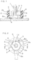
- Figure 1 shows an earthing stud 1, arranged on a metallic article, for the arrangement of a cable terminal 8a, the earthing stud 1 being provided with a plastic part 2 having recesses 3 on its upper portion 2b.
- the plastic part 2 also consists of a lower portion 2a having a hexagonal internal boundary 5, which surrounds the external boundary of the base part 1a of the earthing stud 1, and a circular external diameter 6 coinciding with the external diameter 6 of the upper portion 2b.
- the internal boundary of the upper portion 2b is a circular internal diameter 7.
- the base part 1a of the earthing stud 1 is also hexagonal in design.
- the recesses 3 on the plastic part 2 for fixing the cable terminal 8a are provided in each case at the level of the edges of the internal boundary 5 of the lower portion 2a of the plastic part 2.
- Figure 1 shows that the plastic part 2 has a smaller overall height than the earthing stud 1.
- Figure 2 shows a plan view of the earthing stud according to the invention. This figure shows particularly advantageously the hexagonal design of the internal boundary 5 of the lower portion 2a of the plastic part 2 and the external boundary 4 of the base part 1a of the earthing stud. Figure 2 also shows a cable terminal 8a in broken lines, which is fixed in a firm position via a cable holder 8b in one of the recesses 3 in the plastic part 2.
- Figure 3 is an exploded view showing the plastic part 2, the weld stud 1 and the cable terminal 8a in detail.
- This figure particularly clarifies the design according to the invention of the weld stud 3 with a hexagonal base part 1a and of the plastic part 2 of which the lower portion 2a has an internal boundary 5 matching the base part 1a of the earthing stud 1 and of which the upper portion 2b has recesses 3 for receiving the cable holder 8b of a cable terminal 8a.
- the cable terminal 8a is illustrated above the earthing stud 1. It can be arranged on the earthing stud 1 fixed in a firm position by the plastic part 2.
Landscapes
- Connections By Means Of Piercing Elements, Nuts, Or Screws (AREA)
- Connections Effected By Soldering, Adhesion, Or Permanent Deformation (AREA)
- Clamps And Clips (AREA)
- Supports For Pipes And Cables (AREA)
- Multi-Conductor Connections (AREA)
Abstract
Description
- The present invention relates to an earthing stud designed as a weld stud for the application of a cable terminal with cable holder.
- Known weld studs have a shank and a flange adjacent thereto, the flange having, on its side remote from the shank, a weld face which serves for welding the weld stud onto a metallic article or a metal plate. Such weld studs are used, for example, in the production of motor vehicles for fastening brake tubes, fuel lines and electric leads. If electric leads are to be fastened, the shank preferably has an external thread, the lead is arranged via a cable holder on a cable terminal, and the cable terminal is fastened on the shank by means of a nut.
- A problem which repeatedly poses problems in the fastening of components on weld studs resides in the fact that the components are generally inadequately protected from twisting. Forces and torques of greatly different natures and values act upon the components held by the weld studs owing to the vibrations originating during movement of the vehicle body. As already described in German Gebrauchsmuster application G 84 25 599.4, these torques can lead to twisting of the component relative to the weld stud. The component is therefore loosened, particularly if the shank has spiral projections, i.e. a thread, so that the component can no longer fulfil its function to an optimum. According to the above-mentioned Gebrauchsmuster application, a non-rotatable connection between component and weld stud and a reliable, correctly positioned assembly is achieved in that the shank is divided into two immediately adjacent regions, the first region being provided with substantially radially encircling projections for absorbing an axial force and the second region having several beads for absorbing a torque, these beads being parallel to the axis, being distributed round the periphery, having an external diameter which is greater than the corresponding internal diameter of the bore of the component and pressing themselves in the bore of the component.
- If the component to be fastened, for example a cable terminal, has an extremely small height, this specified solution to the problem is unsuitable. The second region, provided on the flange of the weld stud, with beads, parallel to the axis, should have an equally small height as the component to guarantee that axial displacement cannot occur. However, this is accompanied by problems in production and has the further disadvantage that weld studs of different designs would have to be provided for each different height of different cable terminals. Furthermore, cable terminals are normally produced from a material which is not very strong so the cable terminal could be destroyed when applied to a weld stud provided with axial beads.
- In the case of weld studs with a shank having only a thread and no axially parallel beads, the cable terminal is applied to the weld stud by tightening a nut arranged over the cable terminal. It may happen that the cable terminal is also rotated in a disadvantageous manner. Moreover, it can happen with an earthing stud according to the prior art that the cable terminal twists when the tightened nut is loosened in the course of time, owing to wear, which, in extreme cases, could go so far that the cable terminal or a connected cable of which the protective sheath is destroyed produces a short circuit owing to contact with another cable or component Even though a plastic cap is generally placed over an earthing stud according to the prior art, the aforementioned problem cannot be ignored; the problem of twisting of the cable terminal during fitting of the cable terminal cannot be solved by providing a plastic cap.
- It is accordingly the object of the invention to develop an earthing stud designed as a weld stud for the application of a cable terminal with cable holder such that twisting of the cable terminal is inhibited.
- According to the present invention, an earthing stud for use as a weld stud, for the application of a cable terminal with cable holder has a base part with a non-circular external boundary and is provided with a cooperating plastic part of which the lower portion has an internal boundary matching the external boundary of the base part and of which the upper portion has recesses for receiving the cable holder. The non-circular design of the external diameter of the base part of the earthing stud and the corresponding non-circular design of the lower portion of the plastic part allow a secure non-rotatable connection between the earthing stud and the plastic part. The cable holder of the cable terminal, on which a cable is fastened, is guided through the recesses, advantageously ensuring that the cable terminal is fixed in a firm position and cannot twist even during assembly.
- Accordingly, the external boundary of the base part of the earthing stud and the internal boundary of the lower portion of the plastic part are preferably hexagonal in design. The lower portion of the plastic part may have a circular external diameter; the thinner-walled upper portion equally may have a circular internal diameter and a circular external diameter which coincides with the external diameter of the lower portion. The recesses are preferably provided in each case at the level of the edges of the internal boundary of the plastic part. The entire arrangement is advantageously designed such that the plastic part has a smaller height than the weld stud. When the plastic part is arranged on the earthing stud, the plastic part is pressed onto the earthing stud in order to produce a press fit between the earthing stud and the plastic part. The plastic part is preferably produced as an injection moulding.
- In order that the invention can be better understood, a preferred embodiment will now be described in greater detail by way of example and with reference to the accompanying drawings in which:-
- Figure 1 is a side view of an earthing stud with plastic part according to the invention;
- Figure 2 is a plan view of the earthing stud with plastic part, and
- Figure 3 is an exploded view of the earthing stud with the plastic part and a cable stud.
- Figure 1 shows an earthing stud 1, arranged on a metallic article, for the arrangement of a
cable terminal 8a, the earthing stud 1 being provided with aplastic part 2 havingrecesses 3 on itsupper portion 2b. Theplastic part 2 also consists of alower portion 2a having a hexagonalinternal boundary 5, which surrounds the external boundary of the base part 1a of the earthing stud 1, and a circularexternal diameter 6 coinciding with theexternal diameter 6 of theupper portion 2b. The internal boundary of theupper portion 2b is a circularinternal diameter 7. - The base part 1a of the earthing stud 1 is also hexagonal in design. The
recesses 3 on theplastic part 2 for fixing thecable terminal 8a are provided in each case at the level of the edges of theinternal boundary 5 of thelower portion 2a of theplastic part 2. Figure 1 shows that theplastic part 2 has a smaller overall height than the earthing stud 1. - Figure 2 shows a plan view of the earthing stud according to the invention. This figure shows particularly advantageously the hexagonal design of the
internal boundary 5 of thelower portion 2a of theplastic part 2 and theexternal boundary 4 of the base part 1a of the earthing stud. Figure 2 also shows acable terminal 8a in broken lines, which is fixed in a firm position via acable holder 8b in one of therecesses 3 in theplastic part 2. - Figure 3 is an exploded view showing the
plastic part 2, the weld stud 1 and thecable terminal 8a in detail. This figure particularly clarifies the design according to the invention of theweld stud 3 with a hexagonal base part 1a and of theplastic part 2 of which thelower portion 2a has aninternal boundary 5 matching the base part 1a of the earthing stud 1 and of which theupper portion 2b has recesses 3 for receiving thecable holder 8b of acable terminal 8a. Thecable terminal 8a is illustrated above the earthing stud 1. It can be arranged on the earthing stud 1 fixed in a firm position by theplastic part 2.
Claims (7)
- An earthing stud for use as a weld stud for the application of a cable terminal 8a with cable holder 8b, characterised in that the earthing stud 1 has a base part 1a with a non-circular external boundary 4 and is provided with a cooperating plastic part 2 of which the lower portion 2a has an internal boundary 5 matching the external boundary of the base part 1a and of which the upper portion 2b has recesses 3 for receiving the cable holder 8b.
- Earthing stud according to Claim 1, characterised in that the external boundary 4 of the base part 1a of the earthing stud 1 and the internal boundary 5, matching the external boundary of the base part 1a, of the lower portion 2a of the plastic part 2 are hexagonal in design.
- Earthing stud according to Claim 1 or 2, characterised in that the plastic part 2 has a circular external diameter 6 and in that the upper portion 2b of the plastic part 2 is thin-walled with a circular internal diameter 7.
- Earthing stud according to Claim 2 or 3, characterised in that recesses 3 are provided in each case at the level of the edges of the internal boundary 5 of the plastic part 2.
- Earthing stud according to one of the preceding claims, characterised in that the plastic part 2 has a smaller overall height than the earthing stud 1.
- Earthing stud according to one of the preceding claims, characterised in that the plastic part 2 is pressed onto the earthing stud 1 to produce a press fit.
- Earthing stud according to one of the preceding claims, characterised in that the plastic part 2 is produced as an injection moulding.
Applications Claiming Priority (2)
| Application Number | Priority Date | Filing Date | Title |
|---|---|---|---|
| DE9111564U | 1991-09-17 | ||
| DE9111564U DE9111564U1 (en) | 1991-09-17 | 1991-09-17 | Ground bolt |
Publications (3)
| Publication Number | Publication Date |
|---|---|
| EP0533421A2 true EP0533421A2 (en) | 1993-03-24 |
| EP0533421A3 EP0533421A3 (en) | 1993-06-30 |
| EP0533421B1 EP0533421B1 (en) | 1995-11-22 |
Family
ID=6871354
Family Applications (1)
| Application Number | Title | Priority Date | Filing Date |
|---|---|---|---|
| EP92308349A Expired - Lifetime EP0533421B1 (en) | 1991-09-17 | 1992-09-14 | Earthing stud |
Country Status (6)
| Country | Link |
|---|---|
| US (1) | US5292264A (en) |
| EP (1) | EP0533421B1 (en) |
| JP (1) | JPH05211072A (en) |
| CZ (1) | CZ281308B6 (en) |
| DE (2) | DE9111564U1 (en) |
| ES (1) | ES2079804T3 (en) |
Cited By (7)
| Publication number | Priority date | Publication date | Assignee | Title |
|---|---|---|---|---|
| WO1998013900A1 (en) * | 1996-09-24 | 1998-04-02 | Emhart Inc. | Fastening arrangement |
| EP0853369A3 (en) * | 1996-12-13 | 1999-02-17 | FIAT AUTO S.p.A. | A system for connecting an electrical cable at a predetermined angle to a terminal of electrical apparatus, in particular an alternator for a motor vehicle |
| WO2002067382A1 (en) * | 2001-02-20 | 2002-08-29 | Newfrey Llc | Grounding stud |
| US7056161B2 (en) | 2001-02-20 | 2006-06-06 | Newfrey Llc | Grounding stud |
| US8287219B2 (en) | 2006-11-20 | 2012-10-16 | Newfrey Llc | Fastening arrangement |
| WO2014173687A1 (en) | 2013-04-24 | 2014-10-30 | Newfrey Llc | Contacting device for an electrical contact arrangement, and also method for production thereof |
| EP3407426A1 (en) * | 2017-05-24 | 2018-11-28 | PSA Automobiles SA | Vehicle structure including a means for attaching an electrically conductive tie and corresponding attaching means |
Families Citing this family (23)
| Publication number | Priority date | Publication date | Assignee | Title |
|---|---|---|---|---|
| DE4415618C2 (en) * | 1994-05-04 | 1997-02-13 | Delphi Automotive Systems Gmbh | Device for grounding electrical cables, in particular on a motor vehicle body |
| DE4425839A1 (en) * | 1994-07-21 | 1996-01-25 | Bayerische Motoren Werke Ag | Threaded bolts for providing cable chassis or earth connection in vehicles |
| JPH1155823A (en) * | 1997-07-30 | 1999-02-26 | Sumitomo Wiring Syst Ltd | Jointing device of wire harness for vehicle |
| FR2769404B1 (en) * | 1997-10-08 | 1999-12-24 | Schneider Electric Sa | HOUSING FOR AN ELECTRICAL APPARATUS SUCH AS A CIRCUIT BREAKER |
| DE19749383A1 (en) * | 1997-11-07 | 1999-05-27 | Trw Nelson Bolzenschweisstechn | Collar bolt with anti-twist device |
| US6257903B1 (en) * | 1999-02-05 | 2001-07-10 | Visteon Global Technologies, Inc. | Self-docking electrical connector |
| DE10155644B4 (en) * | 2001-11-13 | 2014-09-18 | Volkswagen Ag | Device as a receiving cage for eyelets arranged on cable ends of a cable harness lugs |
| DE10211154A1 (en) * | 2002-03-14 | 2003-09-25 | Bosch Gmbh Robert | Termination device for electrical machine e.g. starter motor, has 2 electrically-insulating parts, holder and separate conductive part coupled together in non-detachable manner |
| DE102004050675B4 (en) * | 2004-10-18 | 2015-05-07 | Volkswagen Ag | Mounting arrangement for at least one cable lug on a welding bolt |
| DE102004054782B3 (en) | 2004-11-12 | 2006-06-14 | Lisa Dräxlmaier GmbH | Grounding cable lug and stud e.g. grounding stud, mounting arrangement for motor vehicle, has assembly aid detachably connected with distributor and including protruding center unit whose cross-section corresponds to stud cross-section |
| DE102006012761B4 (en) | 2006-03-17 | 2019-03-21 | Volkswagen Ag | Mounting arrangement for at least one cable lug on a welding bolt |
| DE102006015632A1 (en) * | 2006-04-04 | 2007-10-11 | Volkswagen Ag | Screwing device for producing ground closure in motor vehicle, has tool for producing torsional moment, and rotation protection device arranged on device and fixing earth cable during unscrewing threaded bolt in pre-determined position |
| DE102007046690A1 (en) | 2007-09-28 | 2009-04-02 | Volkswagen Ag | Weldable clamp for providing electrical contact in body of motor vehicle, has hexagon cap nut formed between clamping surface and free end of contact studs of free space for accommodating electrical contact |
| DE102007062956B3 (en) * | 2007-12-21 | 2009-09-03 | Lisa Dräxlmaier GmbH | Mounting aid for mounting cable sockets at earthing pin of motor vehicle, has retaining elements and fixing element comprising resting elements to enable fixing element to be fixed in different heights with respect to base element |
| DE102008010352A1 (en) * | 2008-02-13 | 2009-08-20 | Newfrey Llc, Newark | Holding arrangement for cable lugs |
| DE102011076261A1 (en) * | 2011-05-23 | 2012-11-29 | Ford Global Technologies, Llc | Welding pin having a variable, head-side functional area |
| DE102012220293A1 (en) * | 2012-11-07 | 2014-05-08 | Wobben Properties Gmbh | A slip ring transmission |
| US9680239B2 (en) | 2014-04-23 | 2017-06-13 | Ramco Specialties, Inc. | Grounding stud and electrical connections |
| EP3089271B1 (en) * | 2015-04-29 | 2020-03-11 | Nexans | Process and arrangement for mounting a cable lug |
| JP6237723B2 (en) * | 2015-07-23 | 2017-11-29 | 住友電装株式会社 | Laminated connector for bolted terminals and laminated fixing structure |
| EP3210725B1 (en) * | 2016-02-23 | 2019-02-06 | TE Connectivity Germany GmbH | Hand-operated tool, ground contact mounting set and method for mounting a terminal onto a ground stud contact, in particular for a car body |
| US20180241139A1 (en) * | 2017-02-23 | 2018-08-23 | Lear Corporation | Electrical terminal assembly and method of assembling the same |
| CN108183345A (en) * | 2018-01-05 | 2018-06-19 | 哈尔滨工程大学 | The high-voltage cable joint of dismantled and assembled no-welding |
Family Cites Families (7)
| Publication number | Priority date | Publication date | Assignee | Title |
|---|---|---|---|---|
| GB190508548A (en) * | 1905-04-20 | 1905-06-29 | Arthur Downs | Improvements in and relating to Driving Gear for Motor Vehicles applicable also to other Kinds of Machinery. |
| FR611554A (en) * | 1926-02-22 | 1926-10-01 | Cable tie and wires | |
| FR872877A (en) * | 1941-01-29 | 1942-06-22 | Connection device | |
| US4049335A (en) * | 1977-01-10 | 1977-09-20 | Julian Victor J | Sealed battery threaded stud termination |
| US4410226A (en) * | 1981-08-10 | 1983-10-18 | General Motors Corporation | Junction box and connector arrangement |
| DE8425599U1 (en) * | 1984-08-29 | 1985-02-21 | Tucker Gmbh, 6300 Giessen | WELDING BOLTS |
| FR2669778B1 (en) * | 1990-11-22 | 1994-07-22 | Rapid Sa | LOCKED POSITIONING HOLDER FOR AN ELECTRICAL CONNECTION TERMINAL. |
-
1991
- 1991-09-17 DE DE9111564U patent/DE9111564U1/en not_active Expired - Lifetime
-
1992
- 1992-09-14 EP EP92308349A patent/EP0533421B1/en not_active Expired - Lifetime
- 1992-09-14 ES ES92308349T patent/ES2079804T3/en not_active Expired - Lifetime
- 1992-09-14 DE DE69206225T patent/DE69206225T2/en not_active Expired - Lifetime
- 1992-09-15 US US07/945,189 patent/US5292264A/en not_active Expired - Fee Related
- 1992-09-16 CZ CS922844A patent/CZ281308B6/en not_active IP Right Cessation
- 1992-09-17 JP JP4247820A patent/JPH05211072A/en active Pending
Cited By (11)
| Publication number | Priority date | Publication date | Assignee | Title |
|---|---|---|---|---|
| WO1998013900A1 (en) * | 1996-09-24 | 1998-04-02 | Emhart Inc. | Fastening arrangement |
| EP0853369A3 (en) * | 1996-12-13 | 1999-02-17 | FIAT AUTO S.p.A. | A system for connecting an electrical cable at a predetermined angle to a terminal of electrical apparatus, in particular an alternator for a motor vehicle |
| WO2002067382A1 (en) * | 2001-02-20 | 2002-08-29 | Newfrey Llc | Grounding stud |
| US7056161B2 (en) | 2001-02-20 | 2006-06-06 | Newfrey Llc | Grounding stud |
| EP2141773A3 (en) * | 2001-02-20 | 2010-10-27 | Newfrey LLC | Grounding stud |
| US8287219B2 (en) | 2006-11-20 | 2012-10-16 | Newfrey Llc | Fastening arrangement |
| US8523505B2 (en) | 2006-11-20 | 2013-09-03 | Newfrey Llc | Fastening arrangement |
| WO2014173687A1 (en) | 2013-04-24 | 2014-10-30 | Newfrey Llc | Contacting device for an electrical contact arrangement, and also method for production thereof |
| DE102013007036A1 (en) | 2013-04-24 | 2014-10-30 | Newfrey Llc | Contacting device for an electrical contact arrangement and method for its production |
| EP3407426A1 (en) * | 2017-05-24 | 2018-11-28 | PSA Automobiles SA | Vehicle structure including a means for attaching an electrically conductive tie and corresponding attaching means |
| FR3066736A1 (en) * | 2017-05-24 | 2018-11-30 | Peugeot Citroen Automobiles Sa | VEHICLE STRUCTURE COMPRISING A MEANS FOR FIXING AN ELECTRICALLY CONDUCTIVE LINK AND CORRESPONDING FIXING MEANS |
Also Published As
| Publication number | Publication date |
|---|---|
| DE9111564U1 (en) | 1992-01-09 |
| CZ281308B6 (en) | 1996-08-14 |
| DE69206225D1 (en) | 1996-01-04 |
| US5292264A (en) | 1994-03-08 |
| CZ284492A3 (en) | 1993-04-14 |
| ES2079804T3 (en) | 1996-01-16 |
| DE69206225T2 (en) | 1996-06-27 |
| EP0533421B1 (en) | 1995-11-22 |
| JPH05211072A (en) | 1993-08-20 |
| EP0533421A3 (en) | 1993-06-30 |
Similar Documents
| Publication | Publication Date | Title |
|---|---|---|
| EP0533421B1 (en) | Earthing stud | |
| US8701285B2 (en) | Method for producing a hollow fastener element, electrical connections and component assembly | |
| US8105121B2 (en) | Ground terminal fitting with a clamping section touching a ground member | |
| US8287219B2 (en) | Fastening arrangement | |
| US6864015B2 (en) | Anti-rotation terminal connection assembly | |
| US5620290A (en) | Ground retainer | |
| US7357614B2 (en) | Functional element for attaching to a sheet metal part composite component produced from said element and method for attaching the functional element to a sheet metal part | |
| US6027382A (en) | Fastening arrangement | |
| CZ281224B6 (en) | Electric contact nut | |
| US5655936A (en) | Self locking, constant pressure electrical terminal for threaded studs | |
| AU2017206258A1 (en) | Variable-clocking terminal assembly | |
| US9873392B2 (en) | Terminal connection assembly for vehicle power distribution device | |
| WO2000010227A1 (en) | Electrical fastener | |
| US3922058A (en) | Electrical connector | |
| EP1364430B1 (en) | Double-ended grounding bolt | |
| US4932896A (en) | Cable with a jumper terminal | |
| US6433278B1 (en) | Attachment device with cap | |
| US20080145176A1 (en) | Functional element for the attachment to a a sheet metal part, component assembly manufactured from this and also a method for the attachment of a functional element to sheet metal part | |
| CN113841291B (en) | Mounting apparatus and method for mounting nuts onto screws of a battery unit and battery unit | |
| US4952831A (en) | Device for waterproofing around terminal bolt | |
| US4892987A (en) | Mounting for electrical control | |
| JP2010033919A (en) | Battery terminal | |
| US5982636A (en) | Support arrangement for mechanically securing and electrically connecting electronic components such as LEDs as well as method for electrically connecting components to the support member | |
| EP1665468A1 (en) | Grounding element and method for grounding | |
| KR19990030546U (en) | Fixed structure of vehicle ground terminal |
Legal Events
| Date | Code | Title | Description |
|---|---|---|---|
| PUAI | Public reference made under article 153(3) epc to a published international application that has entered the european phase |
Free format text: ORIGINAL CODE: 0009012 |
|
| AK | Designated contracting states |
Kind code of ref document: A2 Designated state(s): BE DE ES FR GB IT |
|
| PUAL | Search report despatched |
Free format text: ORIGINAL CODE: 0009013 |
|
| AK | Designated contracting states |
Kind code of ref document: A3 Designated state(s): BE DE ES FR GB IT |
|
| 17P | Request for examination filed |
Effective date: 19931104 |
|
| 17Q | First examination report despatched |
Effective date: 19950202 |
|
| GRAA | (expected) grant |
Free format text: ORIGINAL CODE: 0009210 |
|
| AK | Designated contracting states |
Kind code of ref document: B1 Designated state(s): BE DE ES FR GB IT |
|
| REF | Corresponds to: |
Ref document number: 69206225 Country of ref document: DE Date of ref document: 19960104 |
|
| REG | Reference to a national code |
Ref country code: ES Ref legal event code: FG2A Ref document number: 2079804 Country of ref document: ES Kind code of ref document: T3 |
|
| ITF | It: translation for a ep patent filed | ||
| ET | Fr: translation filed | ||
| PGFP | Annual fee paid to national office [announced via postgrant information from national office to epo] |
Ref country code: BE Payment date: 19960827 Year of fee payment: 5 |
|
| PLBE | No opposition filed within time limit |
Free format text: ORIGINAL CODE: 0009261 |
|
| 26N | No opposition filed | ||
| PG25 | Lapsed in a contracting state [announced via postgrant information from national office to epo] |
Ref country code: BE Free format text: LAPSE BECAUSE OF NON-PAYMENT OF DUE FEES Effective date: 19970930 |
|
| BERE | Be: lapsed |
Owner name: EMHART INC. Effective date: 19970930 |
|
| REG | Reference to a national code |
Ref country code: GB Ref legal event code: IF02 |
|
| PGFP | Annual fee paid to national office [announced via postgrant information from national office to epo] |
Ref country code: GB Payment date: 20050908 Year of fee payment: 14 |
|
| REG | Reference to a national code |
Ref country code: FR Ref legal event code: CD |
|
| GBPC | Gb: european patent ceased through non-payment of renewal fee |
Effective date: 20060914 |
|
| PG25 | Lapsed in a contracting state [announced via postgrant information from national office to epo] |
Ref country code: GB Free format text: LAPSE BECAUSE OF NON-PAYMENT OF DUE FEES Effective date: 20060914 |
|
| PGFP | Annual fee paid to national office [announced via postgrant information from national office to epo] |
Ref country code: ES Payment date: 20090928 Year of fee payment: 18 |
|
| PGFP | Annual fee paid to national office [announced via postgrant information from national office to epo] |
Ref country code: DE Payment date: 20090929 Year of fee payment: 18 |
|
| PGFP | Annual fee paid to national office [announced via postgrant information from national office to epo] |
Ref country code: IT Payment date: 20090929 Year of fee payment: 18 |
|
| PG25 | Lapsed in a contracting state [announced via postgrant information from national office to epo] |
Ref country code: IT Free format text: LAPSE BECAUSE OF NON-PAYMENT OF DUE FEES Effective date: 20100914 |
|
| REG | Reference to a national code |
Ref country code: FR Ref legal event code: ST Effective date: 20110531 |
|
| REG | Reference to a national code |
Ref country code: DE Ref legal event code: R119 Ref document number: 69206225 Country of ref document: DE Effective date: 20110401 |
|
| PG25 | Lapsed in a contracting state [announced via postgrant information from national office to epo] |
Ref country code: FR Free format text: LAPSE BECAUSE OF NON-PAYMENT OF DUE FEES Effective date: 20100930 Ref country code: DE Free format text: LAPSE BECAUSE OF NON-PAYMENT OF DUE FEES Effective date: 20110401 |
|
| PGFP | Annual fee paid to national office [announced via postgrant information from national office to epo] |
Ref country code: FR Payment date: 20091006 Year of fee payment: 18 |
|
| REG | Reference to a national code |
Ref country code: ES Ref legal event code: FD2A Effective date: 20111019 |
|
| PG25 | Lapsed in a contracting state [announced via postgrant information from national office to epo] |
Ref country code: ES Free format text: LAPSE BECAUSE OF NON-PAYMENT OF DUE FEES Effective date: 20100915 |