EP0534648A1 - Procédé d'exploration sismique maritime - Google Patents
Procédé d'exploration sismique maritime Download PDFInfo
- Publication number
- EP0534648A1 EP0534648A1 EP92308278A EP92308278A EP0534648A1 EP 0534648 A1 EP0534648 A1 EP 0534648A1 EP 92308278 A EP92308278 A EP 92308278A EP 92308278 A EP92308278 A EP 92308278A EP 0534648 A1 EP0534648 A1 EP 0534648A1
- Authority
- EP
- European Patent Office
- Prior art keywords
- geophone
- hydrophone
- signals
- signal
- filter
- Prior art date
- Legal status (The legal status is an assumption and is not a legal conclusion. Google has not performed a legal analysis and makes no representation as to the accuracy of the status listed.)
- Granted
Links
Images


Classifications
-
- G—PHYSICS
- G01—MEASURING; TESTING
- G01V—GEOPHYSICS; GRAVITATIONAL MEASUREMENTS; DETECTING MASSES OR OBJECTS; TAGS
- G01V1/00—Seismology; Seismic or acoustic prospecting or detecting
- G01V1/38—Seismology; Seismic or acoustic prospecting or detecting specially adapted for water-covered areas
- G01V1/3808—Seismic data acquisition, e.g. survey design
-
- G—PHYSICS
- G01—MEASURING; TESTING
- G01V—GEOPHYSICS; GRAVITATIONAL MEASUREMENTS; DETECTING MASSES OR OBJECTS; TAGS
- G01V1/00—Seismology; Seismic or acoustic prospecting or detecting
- G01V1/16—Receiving elements for seismic signals; Arrangements or adaptations of receiving elements
-
- G—PHYSICS
- G01—MEASURING; TESTING
- G01V—GEOPHYSICS; GRAVITATIONAL MEASUREMENTS; DETECTING MASSES OR OBJECTS; TAGS
- G01V1/00—Seismology; Seismic or acoustic prospecting or detecting
- G01V1/28—Processing seismic data, e.g. for interpretation or for event detection
- G01V1/36—Effecting static or dynamic corrections on records, e.g. correcting spread; Correlating seismic signals; Eliminating effects of unwanted energy
- G01V1/364—Seismic filtering
-
- G—PHYSICS
- G01—MEASURING; TESTING
- G01V—GEOPHYSICS; GRAVITATIONAL MEASUREMENTS; DETECTING MASSES OR OBJECTS; TAGS
- G01V13/00—Manufacturing, calibrating, cleaning, or repairing instruments or devices covered by groups G01V1/00 – G01V11/00
-
- G—PHYSICS
- G01—MEASURING; TESTING
- G01V—GEOPHYSICS; GRAVITATIONAL MEASUREMENTS; DETECTING MASSES OR OBJECTS; TAGS
- G01V2210/00—Details of seismic processing or analysis
- G01V2210/20—Trace signal pre-filtering to select, remove or transform specific events or signal components, i.e. trace-in/trace-out
- G01V2210/21—Frequency-domain filtering, e.g. band pass
-
- G—PHYSICS
- G01—MEASURING; TESTING
- G01V—GEOPHYSICS; GRAVITATIONAL MEASUREMENTS; DETECTING MASSES OR OBJECTS; TAGS
- G01V2210/00—Details of seismic processing or analysis
- G01V2210/50—Corrections or adjustments related to wave propagation
- G01V2210/56—De-ghosting; Reverberation compensation
Definitions
- This invention relates generally to marine seismic exploration.
- a seismic survey ship In marine seismic exploration, a seismic survey ship is equipped with an energy source and a receiver for taking seismic profiles of an underwater land configuration.
- the act of taking profiles is often referred to as "shooting" due to the fact that explosive devices have been commonly used for many years as energy sources.
- the energy source is designed to produce compressional waves that propagate through the water and into the underwater land formation. As the compressional waves propagate through the land formation, they strike interfaces between formations, commonly referred to as strata, and reflect back through the earth and water to the receiver.
- the receiver typically converts the received waves into electrical signals which are then processed into an image that provides information about the structure of the subterranean formation.
- one of the most common energy sources is an air gun that discharges air under very high pressure into the water.
- the discharged air forms a pulse which contains frequencies within the seismic range.
- Another energy source which is frequently used is a marine vibrator
- Marine vibrators typically include a pneumatic or hydraulic actuator that causes an acoustic piston to vibrate at a range of selected frequencies. The vibrations of the acoustic vibrator produce pressure differentials in the water which generate seismic pulses free from spurious bubbles.
- hydrophones convert pressure waves into electrical signals that are used for analog or digital processing.
- the most common type of hydrophone includes a piezoelectric element which converts physical signals, such as pressure, into electrical signals. Hydrophones are usually mounted on a long streamer which is towed behind the survey ship at a depth of about 30 feet.
- marine seismic techniques may use different types of receivers which detect different characteristics of the environment.
- a combination of pressure sensitive transducers, such as hydrophones, and particle velocity transducers, such as geophones can be deployed on the marine bottom.
- pressure sensitive transducers such as hydrophones
- particle velocity transducers such as geophones
- geophones are typically used in land operations where metal spikes anchor the geophones to the ground to ensure fidelity of geophone motion to ground motion
- geophones cannot be economically anchored in marine applications. Therefore, cylindrical, gimbal geophones are attached to the bottom-cable. After the cable is deployed from the seismic survey ship, the geophones simply lie in contact with the marine bottom where they fall. The gimbal mechanism inside the cylinder assures that the geophone element mounted therein is oriented vertically for proper operation.
- a marine seismic exploration method which comprises the steps of: generating a seismic wave into a marine environment; detecting water pressure at a first position in said marine environment resulting from said seismic wave and generating a first signal correlative to said detected pressure; detecting particle velocity at a second position in said marine environment resulting from said seismic wave and generating a second signal correlative to said detected velocity; and calculating a filter transfer function using said first and second signals, said filter transfer function substantially equalizing response characteristics between said first and second signals.
- the first and second signals are transformed into first and second frequency domain signals, respectively. Then, one of the frequency domain signals is divided by the other to produce the filter transfer function. If the filter transfer function is intended to compensate the second signal from the geophone for the response difference due to the imperfect coupling of the geophone, the first frequency domain signal is divided by the second frequency domain signal to obtain the filter transfer function. After the filter transfer function has been transformed into a time domain filtering function, subsequent second signals are filtered by the time domain filtering function.
- a method of calibrating a geophone/hydrophone receiver pair in a marine environment comprising the steps of deploying said geophone/hydrophone receiver pair in said marine environment; generating a seismic wave into said marine environment, generating a first signal correlative to a detected pressure through implementation of said hydrophone detecting water pressure resulting from receiving said seismic wave; generating a second signal correlative to a detected velocity through implementation of said geophone detecting particle velocity resulting from receiving said seismic wave; transforming said first and second signals into first and second frequency domain signals, respectively; dividing one of said first and second frequency domain signals by the other of said first and second frequency domain signals to obtain a filter transfer functions transforming said filter transfer function into a time domain filter; and applying said time domain filter to one of said first and second signals generated as a result of subsequent seismic waves.
- the invention provides a method of correcting a coupling difference between a hydrophone and a geophone in a marine environment, said method comprising the steps of placing said hydrophone in said marine environment, said hydrophone being perfectly coupled with said marine environment; placing said geophone in said marine environment, said geophone being imperfectly coupled with said marine environment; generating a calibration wave into said marine environment, said calibration wave being a primary seismic wave having a magnitude substantially equal to a magnitude of a reflected seismic wave produced during production shooting; detecting a signal produced by said hydrophone in response to said seismic wave, said hydrophone signal being influenced by an electrical impulse response of said hydrophone; detecting a signal produced by said geophone in response to said seismic wave, said geophone signal being influenced by an electrical impulse response of said geophone and by a mechanical impulse response of said geophone produced by said imperfect coupling; transforming said hydrophone signal and said geophone signal into first and second frequency domain signals, respectively; dividing one of said first and second frequency domain signals by the other of said first and second frequency domain signals to
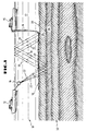
- the system 10 includes a seismic survey ship 12 that is adapted for towing a seismic energy source 14 through a body of water 17.
- the seismic energy source 14 is an acoustic energy source or an array of such sources.
- An acoustic energy source preferred for use with the system 10 is a compressed air gun, called a "sleeve gun", which is commercially available from Halliburton Geophysical services, Inc. of Houston, Texas.
- the source 14 is constructed and operated in a manner conventional in the art.
- the system 10 also includes a receiving ship 15 that is preferably anchored in the body of water 17.
- the receiving ship 15 deploys a cable 16 on the marine bottom 20, and receives signals from the cable 16 as will be subsequently explained in detail.
- One preferred cable is commercially available from Tescorp Seismic Products co. of Houston, Texas, but those skilled in the art recognize that any one of a wide variety of cables can be used.
- the cable 16 carries at least one receiver 18, but preferably includes a plurality of such units.
- the receiver 18 includes a hydrophone for detecting water pressure and a geophone for detecting water-bottom particle velocity. More particularly, the hydrophones and geophones on the cable 16 are arranged in identical spatial arrays when deployed on the marine bottom 20. Each individual hydrophone has a gimballed geophone positioned next to it. A separate electrical signal is sent to a recording system on the ship 15 for each hydrophone and each geophone spatial array. The survey ship 12 fires the source 14 at predetermined locations while the signals from the hydrophone and geophone arrays are recorded. These signals are typically referred to as reflection data. The data is recorded by a multi-channel seismic recording system that selectively amplifies, conditions and records time-varying electrical signals onto magnetic tape.
- the system also digitizes the received signals, using a 14 bit analog-to-digital converter for instance, to facilitate signal analysis.
- the ship 15 utilizes a seismic recording system which is commercially available from Halliburton Geophysical Services, Inc.
- a seismic recording system which is commercially available from Halliburton Geophysical Services, Inc.
- Halliburton Geophysical Services, Inc any one of a variety of seismic recording systems can be used.
- the cable 16 and hydrophone/geophone pair 18 are positioned on the marine bottom 20 for use in three-dimensional, "bottom-cable" operations.
- normal production shooting takes place with the survey ship 12 moving at a constant speed along a set of parallel lines, or swath, with respect to the cable 16.
- the receiving ship 15 or other suitable ship retrieves the cable 16 and re-deploys the cable 16 in a line spaced from, but parallel to, the previous cable location. Once the cable 16 is redeployed, the survey ship 12 shoots another swath.
- seismic waves generated by the source 14 travel downwardly, as indicated by the rays 22. These primary waves are reflected off of interfaces between strata, such as the interface 28 between strata 24 and 26, in the subterranean earth formation 32. The reflected waves travel upwardly, as illustrated by the rays 30.
- the hydrophone/geophone pairs that make up each receiver 18 detect the reflected waves.
- the receivers 18 generate electrical signals representative of pressure and particle velocity changes inherent to the wave field, and transmit these generated electrical signals back to the survey ship 15 via the cable 16.
- the recording equipment within the ship 15 records these electrical signals so that they can be subsequently processed to map the subterranean earth formation 32.
- the receivers 18 not only detect the reflected waves of interest, but also the primary wave and reverberated waves.
- Reverberated waves are reflected waves which reflect off of the water-air interface at the surface of the water 17 and travel downwardly in the water 17 to impinge on the receivers 18.
- Reverberated waves are illustrated by the rays 33 in Fig. 1. The effects of reverberated waves will be discussed subsequently with reference to our U.S. patent specification no. 4,979,150 to which reference should be made for further details.
- Fig. 2 illustrates a receiver 18 which includes a gimbal geophone 34 and a hydrophone 36.
- the geophone is a Model SG-1 which is commercially available from SENSOR Nederland b.v. of Voorschoten, Holland
- the hydrophone is a Model MP-24 which is commercially available from OYO Geospace corp. of Houston, Texas.
- the geophone 34 and hydrophone 36 are lying on the marine bottom 20, and together comprise a hydrophone/geophone pair.
- dual-sensor detection techniques offer certain advantages because hydrophones detect pressure variations and geophones detect particle velocity variations.
- hydrophones and geophones typically exhibit different impulse response characteristics due, in part, to differences in design.
- the transfer functions of the geophone 34 and of the hydrophone 36 determine how the signals that they output correspond to any given input. If the seismic survey system 10 used only one type of receiver or the other, the transfer function of the particular receiver would initially be of interest to determine how the receiver would respond to a variety of foreseeable inputs. But past this determination, the impulse response of any particular type of receiver would be of relatively little importance when processing the signals delivered from such receivers. However, when the seismic survey system 10 includes different types of receivers, such as in the dual-sensor configuration described herein, the recording and/or processing of the electrical signals delivered by such receivers requires that the signal from one type of receiver be combined in some fashion with the signal from another type of receiver.
- a separate electrical signal is sent to the recording system from each hydrophone and each geophone array.
- the received signals are referred to as reflection data.
- the recorded hydrophone and geophone reflection data are demultiplexed, gain-removed, and amplitude recovered using identical amplitude recovery curves.
- the gain-removal process properly uses the K-gain settings of the recording instruments.
- the impulse response of each type of receiver should be substantially identical in order to avoid differences in the respective signals due solely to the impulse response of the respective types of receivers.
- the system 10 uses a filter designed in accordance with the theoretical or measured impulse responses of the hydrophones and geophones to convert the phase spectrum and normalized amplitude spectrum of the geophone to match that of the hydrophone, or vice versa.
- v(t) represents the impulse response of the geophone 34
- p(t) represents the impulse response of the hydrophone 36
- h(t) represents the impulse response of a filter 46 which transforms the impulse response of the geophone 34 to equal the impulse response of the hydrophone 36. Therefore, when the signal delivered by the geophone 34 is delivered to the filter 46, the filter 46 modifies the signal to have the same amplitude and phase characteristics as the signal delivered by the hydrophone 36.
- the impulse response h(t) of the filter 46 is designed in the frequency domain by dividing the amplitude spectrum of p(t) by the amplitude spectrum of v(t) and subtracting the phase spectrum of v(t) from the phase spectrum of p(t), as the following equation illustrate mathematically.
- each of the time domain signals are transformed into the frequency domain using an appropriate function, such as a Fourier transform.
- this filter 46 The shortcoming of this filter 46 is that by using it one assumes that the geophone 34 moves in perfect synchronization with the particles of the marine bottom 20 as a seismic wave arrives either from the earth formation 32 or from the water 17.
- metal spikes approximately two to three inches long are fitted to the bottoms of all geophone cases.
- the geophone package is designed to have a density approximately equal to the density of the earth material at the location where the geophone is to be planted. Therefore, when the geophone is planted using the spikes, excellent fidelity of geophone case motion to particle motion results.
- the geophones 34 and hydrophones 36 are deployed in water that may be hundreds of feet deep. Unfortunately, planting the geophones 34 with spikes is impossible, or at least very impractical. Therefore, as mentioned previously, a gimbal mechanism is used to assure that the geophones 34 remain vertically oriented for proper operation when the geophones 34 contact the marine bottom 20. However, since the geophones 34 are not rigidly connected to the marine bottom 20, they do not move exactly in phase or with the same amplitude as the marine bottom particles when a seismic wave arrives.
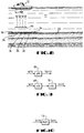
- a coupling mechanism 50 which models this problem is illustrated in Fig. 6. As illustrated, both the geophone 34 and the hydrophone 36 are coupled to the marine bottom 20.
- the double-headed arrow 52 represents the direction of pressure waves impinging upon the hydrophone 36.
- the pressure waves may either propagate downwardly in the water 17 or upwardly from a reflection in the subterranean formation 32. Since the hydrophone 36 is perfectly coupled to the water to receive pressure waves, the hydrophone 36 is illustrated as being directly connected to the marine bottom 20.
- the double-headed arrow 54 represents the direction of particle motion of the marine bottom 20.
- the coupling mechanism 50 represents an analytical model of this coupling imperfection.
- the geophone 34 responds to movement of the water bottom 20 as if it were connected to the water bottom 20 by an unsprung mass m, a spying 56 having a spring constant k, and a damper 58 having a damping constant B.
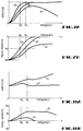
- Fig. 7 illustrates the expected effect of imperfect coupling on the geophone's response to a seismic impulse.
- Fig. 7 illustrates the impulse responses of the geophone 34 and hydrophone 36 after having been transformed into the frequency domain. Therefore, curve 60 represents the amplitude with respect to frequency transfer function of the system which includes the geophone 34 and the coupling mechanism 50.
- the curve 62 illustrates the phase with respect to frequency transfer function of the geophone 34 and coupling mechanism 50.
- the curves 38-44 are reproduced for ease of comparison with the curves 60 and 62.
- the curves 60 and 62 show that the amplitude response of the geophone 34 is less sensitive to high frequencies than it would normally be if it were perfectly coupled. Moreover, its response is delayed, as indicated by the increased phase lag of the curve 62 with respect to the curve 42.
- the imperfect geophone coupling should be taken into account when correcting the impulse response of the hydrophone/geophone pair 18 during recording and processing.
- the problem with ignoring the imperfect coupling of the geophone 34 and the effect it has on the response of the geophone 34 is apparent from the previous discussion. If the filter 46 were applied to the geophone signal in order to match the impulse response of the geophone 34 to the impulse response of the hydrophone 36, engineers entrusted with recording and processing the data from the hydrophone/geophone pair 18 would assume that the filter 46 compensated for any differences in response between the hydrophone 36 and the geophone 34. However, the filter 46 does not compensate for the difference in response of the geophone 34 caused by the imperfect coupling of the geophone 34 with the marine bottom 20. Hence, the impulse responses of the geophone 14 and the hydrophone 36 are still different even though the filter 46 provides partial compensation in the illustrated example of Fig. 7.
- a filter 72 having an appropriate response is designed as illustrated in Fig. 10. While the filter 72 can be designed either theoretically or empirically, the following discussion describes a preferred practical method, in accordance with the previously discussed theoretical assumptions, for determining the appropriate response of the filter 72.
- the survey ship 12 After the cable 16 has been deployed on the marine bottom 20, as illustrated in Fig. 8, the survey ship 12 performs a calibration shooting operation.
- the calibration operation includes recording the responses of the geophones 34 and hydrophones 36 to a downwardly propagating seismic wave produced by the seismic energy source 14.
- the seismic energy source 14 generates a wavefront 64 having a waveform w(t), which is referred to as the primary wave generated by the seismic energy source 14. Recall that the primary wave was defined in Fig. 1 using the rays 22.
- the source 14 includes an array of air guns which are fired simultaneously. However, during the calibration shooting operation, firing the entire array may overdrive the receivers 18. Therefore, only a portion of the air gun array, such as one or two guns, is used during calibration. As will be recognized by those skilled in the art, the number of guns used depends on parameters such as water depth, air gun volume, and the electrical characteristics of the receivers.
- the response of the geophones 34 and of the hydrophones 36 to the impinging wavefront 64 is illustrated in the block diagram of Fig. 9 where p(t) in block 66 represents the impulse response of a hydrophone 36, v(t) in block 68 represents the impulse response of a geophone 34, and c(t) in block 70 represents the impulse response of the coupling mechanism 50.
- p(t) in block 66 represents the impulse response of a hydrophone 36
- v(t) in block 68 represents the impulse response of a geophone 34
- c(t) in block 70 represents the impulse response of the coupling mechanism 50.
- the response of each of the hydrophones 36 is equal to the impact of the wavefront 64 defined as w(t) filtered by the impulse response p(t) of the hydrophone 36.
- the response of each of the geophones 34 is equal to the impact w(t) of the wavefront 64 filtered by both the impulse response v(t) of the geophone 34 and the impulse response c(t) of the coupling mechanism 50.
- the filter 72 having an impulse response h c (t) can be designed which will transform the response s ⁇ (t) of the geophone 34 into the response s p (t) of the hydrophone 36, as illustrated in Fig. 10.
- s p ( ⁇ ) s v ( ⁇ ) H c ( ⁇ ).
- the filter 72 having a transfer function H c ( ⁇ ) is designed by dividing the Fourier transform of the hydrophone's recorded waveform s p (t) by the Fourier transform of the geophone's recorded waveform s v (t).
- H c ( ⁇ ) S p ( ⁇ )
- S v ( ⁇ ) P( ⁇ ) W( ⁇ ) V( ⁇ ) C( ⁇ )
- W( ⁇ ) P( ⁇ ) V( ⁇ ) C( ⁇ )
- the transfer function of the filter 72 is illustrated in Fig. 11.
- the curve 74 shows an increased amplitude spectrum boost as compared with the curve 48 which represents the amplitude spectrum of the filter 46.
- the curve 76 shows an increased phase spectrum correction as compared with the curve 49 which represents the phase spectrum for the filter 46. Therefore, the filter 72 having the transfer function characteristics illustrated in Fig. 11 will compensate the respective curves 60 and 62 so that the compensated impulse response signal from the geophone 34 will be substantially equal to the impulse response signal from the hydrophone 36.
- the filter 72 once designed, is then applied to the geophone data traces recorded during production shooting.
- this technique is used in conjunction with the reverberation attenuation technique disclosed in the referenced patent.
- the above-described method may be used in conjunction with a method which also corrects geophone data for optimum reverberation attenuation, a slight modification of the foregoing explanation is required.
- the responses of the geophones 34 and hydrophones 36 to a downwardly propagating wavefront 64 are opposite in polarity. Therefore, before the filter 72 may be designed in accordance with the above method, the polarity of the recorded geophone response s v (t) is reversed.
- the filter 72 would perform this polarity reversal on the production seismic reflection data transmitted by the geophones 34, and, thus, the destructive reverberation energy would be enhanced instead of attenuated.
- the amplitude of the hydrophone's response to the wavefront 64 is affected by the water bottom reflection coefficient K r and is proportional to (1+K r ).
- the amplitude of the geophone's response to the wavefront 64 is similarly affected by the marine bottom reflection coefficient K r and is proportional to (1-K r ).
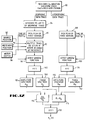
- Fig. 12 illustrates a flow diagram 80 which represents a preferred way to perform the method for designing the filter 72.
- the survey ship 12 performs at least one calibration shooting pass. This step involves firing the energy source 14 directly above the receivers 18 and recording the resulting signals from the geophones 34 and hydrophones 36, as shown in block 82.
- the recording equipment receives a signal from each of the receivers 18 the survey ship may begin production shooting.
- the survey ship 12 performs both the production shooting immediately following the calibration shooting, so that all of the shooting is recorded for processing at a later time.
- a Model 3090 IBM mainframe computer running a "TIPEX" operating system (commercially available from Halliburton Geophysical services, Inc. of Houston, Texas) is used to process the calibration and reflection data.
- the processor designs the filter 72 using the calibration data and, then, applies the filter 72 to reflection data from the respective geophones.
- the following portion of the flow diagram 80 refers to the design of the filter 72 using the calibration data.
- the processor reverses the polarity of the geophone data trace for the reasons previously mentioned.
- peak detectors receive the geophone and hydrophone data traces to determine the peaks of the first arrival waveforms output by the geophones 34 and hydrophones 36, respectively.
- this peak detection is performed interactively using a personal computer program called "PC Analysis.”
- PC Analysis is a general data analysis program that contains a variety of signal processing subroutines, such as a multi-channel seismic event selecting algorithm used here, and is used by Halliburton Geophysical services, Inc.
- This program can generate a text file which denotes, among other things, the time of occurrence of the picked peaks, referred to herein as t p .
- t p the time of occurrence of the picked peaks
- any one of a variety of other types of peak detectors such as the one found in STATIX, a software package available from Sierra Geophysics, Inc. of Seattle, Washington, may be used instead.
- the time corresponding to the peaks of the primary wavefront will be used to isolate the effects of the primary wavefront from the effects of reflected or reverberated wavefronts.
- Block 90 receives the position of the source 14 from block 92, the position of the receiver 19 from block 94, and information regarding the depth of the water 17 from block 96.
- this information is generated by the crew of the survey ship 12 as part of its normal data generation activity.
- the crew uses a radio navigation system that typically includes three or more radio transmitters that are positioned at known locations on shore. These transmitters cooperate with receivers on board the ship to enable the system to compute the exact location of the ship during surveying.
- the crew uses a radio navigation system called "Syledis” which is commercially available from Sercel, Inc. of France.
- the angle of arrival of the seismic waveform w(t), with respect to a vertical reference is calculated using simple algebraic manipulation in view of the geometrical relationships obtained from the blocks 92-96.
- the effect of a non-zero angle of incidence upon the amplitude of the geophone's response is removed by multiplying its data trace by the reciprocal of the cosine of that angle, as illustrated in block 90.
- a window function is generated and applied to the geophone and hydrophone data traces.
- the window function isolates the electrical signals resulting from the primary wave from the electrical signals resulting from reflected or reverberated waves.
- a value for ⁇ t which has worked very well is 26 milliseconds.
- the Fourier transforms of the resulting geophone and hydrophone traces are computed in blocks 102 and 104.
- traditional Fast Fourier transforms are used to transform the incoming signals from the time domain to the frequency domain.
- One computer algorithm for a Fast Fourier Transform is given by W. H. Press, et al., Numerical Recipes: The Art of Scientific computing , Cambridge University Press 1986 (reprinted 1988).
- the amplitude spectrum for the geophone trace is calculated; in block 108, the phase spectrum for the geophone trace is calculated; in block 110, the amplitude spectrum for the hydrophone trace is calculated; and, in block 112, the phase spectrum for the hydrophone trace is calculated.
- the amplitude spectrum from the hydrophone data trace is divided by the amplitude spectrum of the geophone data trace in block 114.
- the phase spectrum of the geophone trace is subtracted from the phase spectrum of the hydrophone trace.
- the impulse function h c (t) i.e., the filtering function describing the filter 72
- the processor stores the filtering function on a hard disk on the mainframe, as is well known in the art.
- the processor applies the filtering function to the geophone data trace prior to processing the geophone data trace with the corresponding hydrophone data trace.
- the method described in the flow diagram 80 is performed for each hydrophone/geophone pair location so that a separate filter 72 is designed for each hydrophone/ geophone pair 18.
- every data trace recorded by the geophones 34 at a particular receiver location during the production of seismic reflection data gathering is filtered by a particular filter 72.
- the filtered geophone data traces are then summed with the corresponding hydrophone data traces at each receiver location to optimally attenuate any reverberation energy arriving at the hydrophone/geophone pair from above, in accordance with the method described in the referenced patent.
Landscapes
- Life Sciences & Earth Sciences (AREA)
- Physics & Mathematics (AREA)
- Engineering & Computer Science (AREA)
- Geophysics (AREA)
- General Life Sciences & Earth Sciences (AREA)
- General Physics & Mathematics (AREA)
- Remote Sensing (AREA)
- Acoustics & Sound (AREA)
- Environmental & Geological Engineering (AREA)
- Geology (AREA)
- Manufacturing & Machinery (AREA)
- Oceanography (AREA)
- Geophysics And Detection Of Objects (AREA)
- Investigating Or Analyzing Materials By The Use Of Magnetic Means (AREA)
Applications Claiming Priority (2)
| Application Number | Priority Date | Filing Date | Title |
|---|---|---|---|
| US07/767,248 US5163028A (en) | 1991-09-27 | 1991-09-27 | Method for correcting impulse response differences of hydrophones and geophones as well as geophone coupling to the water-bottom in dual-sensor, bottom-cable seismic operations |
| US767248 | 1991-09-27 |
Publications (2)
| Publication Number | Publication Date |
|---|---|
| EP0534648A1 true EP0534648A1 (fr) | 1993-03-31 |
| EP0534648B1 EP0534648B1 (fr) | 1996-02-14 |
Family
ID=25078934
Family Applications (1)
| Application Number | Title | Priority Date | Filing Date |
|---|---|---|---|
| EP92308278A Expired - Lifetime EP0534648B1 (fr) | 1991-09-27 | 1992-09-11 | Procédé d'exploration sismique maritime |
Country Status (7)
| Country | Link |
|---|---|
| US (1) | US5163028A (fr) |
| EP (1) | EP0534648B1 (fr) |
| CA (1) | CA2079179A1 (fr) |
| DE (1) | DE69208310T2 (fr) |
| DK (1) | DK0534648T3 (fr) |
| NO (1) | NO304399B1 (fr) |
| SG (1) | SG47791A1 (fr) |
Cited By (5)
| Publication number | Priority date | Publication date | Assignee | Title |
|---|---|---|---|---|
| FR2743896A1 (fr) * | 1996-01-23 | 1997-07-25 | Geophysique Cie Gle | Procede de traitement de calibration d'une paire de capteurs hydrophone/geophone et procede de prospection sismique mettant en oeuvre ce traitement |
| EP0872743A3 (fr) * | 1997-04-14 | 1999-03-10 | Western Atlas International, Inc. | Capteurs sismiques |
| EP0911648A3 (fr) * | 1997-10-22 | 2001-05-23 | Western Atlas International, Inc. | Traitement des données d'exploration sismique |
| GB2404736A (en) * | 2003-08-01 | 2005-02-09 | Westerngeco Seismic Holdings | Determining geophone ground coupling information from power spectrum of acquired seismic record |
| WO2013142854A1 (fr) * | 2012-03-23 | 2013-09-26 | Schlumberger Canada Limited | Analyse quantitative de données sismiques répétitives |
Families Citing this family (38)
| Publication number | Priority date | Publication date | Assignee | Title |
|---|---|---|---|---|
| US5408440A (en) * | 1993-03-19 | 1995-04-18 | Western Atlas International, Inc. | Hydrophone circuit with electrical characteristics of a geophone |
| US5365492A (en) * | 1993-08-04 | 1994-11-15 | Western Atlas International, Inc. | Method for reverberation suppression |
| US5396472A (en) | 1993-09-24 | 1995-03-07 | Western Atlas International | Method for deriving water bottom reflectivity in dual sensor seismic surveys |
| US5774416A (en) * | 1995-04-07 | 1998-06-30 | Pgs, Tensor, Inc. | Method and device for attenuating water column reverberations using co-located hydrophones and geophones in ocean bottom seismic processing |
| US5621699A (en) * | 1995-07-07 | 1997-04-15 | Pgs Ocean Bottom Seismic, Inc. | Apparatus and method of calibrating vertical particle velocity detector and pressure detector in a sea-floor cable with in-situ passive monitoring |
| US5724306A (en) | 1995-12-29 | 1998-03-03 | Western Atlas International, Inc. | Method for correcting dual sensor data for imperfect geophone coupling using production seismic data |
| FR2743897B1 (fr) * | 1996-01-23 | 1998-04-10 | Geophysique Cie Gle | Procede de prospection sismique marine au moyen d'un couple de capteurs hydrophone et geophone |
| US5754492A (en) * | 1996-02-12 | 1998-05-19 | Pgs Tensor, Inc. | Method of reverberation removal from seismic data and removal of dual sensor coupling errors |
| US5696734A (en) * | 1996-04-30 | 1997-12-09 | Atlantic Richfield Company | Method and system for eliminating ghost reflections from ocean bottom cable seismic survey signals |
| US5621700A (en) * | 1996-05-20 | 1997-04-15 | Schlumberger Technology Corporation, Geco-Prakla Div. | Method for attenuation of reverberations using a pressure-velocity bottom cable |
| US5774417A (en) * | 1996-10-25 | 1998-06-30 | Atlantic Richfield Company | Amplitude and phase compensation in dual-sensor ocean bottom cable seismic data processing |
| US6201764B1 (en) | 1997-10-31 | 2001-03-13 | Input/Output, Inc. | Apparatus and method for correcting for capacitance variations in hydrophones |
| US6151275A (en) * | 1998-09-11 | 2000-11-21 | Pgs Tensor, Inc. | Method of dual wavefield reinforcement |
| US6246637B1 (en) | 1998-09-28 | 2001-06-12 | Pgs Tensor, Inc. | Method and system for combining three component seismic data |
| NO307482B2 (no) | 1998-11-13 | 2000-04-10 | Arne Rokkan | Seismisk bunnkabel med sensorenheter tyngre enn kabelen |
| US6263285B1 (en) | 1999-09-15 | 2001-07-17 | Pgs Tensor, Inc. | Amplitude spectra estimation |
| EP1089092A1 (fr) * | 1999-10-01 | 2001-04-04 | Baggermaatschappij Boskalis B.V. | Méthode et appareil pour la mesure de paramètres physiques à partir des histoires de phase et d'amplitude d'un signal acoustique |
| US20020118602A1 (en) | 2001-02-27 | 2002-08-29 | Sen Mrinal K. | Angle dependent surface multiple attenuation for two-component marine bottom sensor data |
| US7310287B2 (en) * | 2003-05-30 | 2007-12-18 | Fairfield Industries Incorporated | Method and apparatus for seismic data acquisition |
| US7561493B2 (en) | 2003-05-30 | 2009-07-14 | Fairfield Industries, Inc. | Method and apparatus for land based seismic data acquisition |
| GB2410551B (en) * | 2004-01-30 | 2006-06-14 | Westerngeco Ltd | Marine seismic acquisition system |
| GB2412732B (en) * | 2004-04-03 | 2006-05-17 | Westerngeco Ltd | Wavefield decomposition for cross-line survey |
| US7254093B2 (en) * | 2004-05-18 | 2007-08-07 | Fairfield, Industries, Inc. | Ocean bottom seismometer package with distributed geophones |
| US7225662B2 (en) * | 2004-08-27 | 2007-06-05 | Schlumberger Technology Corporation | Geophone calibration technique |
| US8534959B2 (en) | 2005-01-17 | 2013-09-17 | Fairfield Industries Incorporated | Method and apparatus for deployment of ocean bottom seismometers |
| US8127706B2 (en) * | 2005-05-02 | 2012-03-06 | Fairfield Industries Incorporated | Deck configuration for ocean bottom seismometer launch platforms |
| US7433265B2 (en) * | 2005-10-04 | 2008-10-07 | Fairfield Industries, Inc. | Converted wave energy removal from seismic data |
| US8077541B2 (en) | 2007-10-19 | 2011-12-13 | Westerngeco L.L.C. | Testing a sensor to produce a filter for noise attenuation |
| US8611191B2 (en) | 2008-05-22 | 2013-12-17 | Fairfield Industries, Inc. | Land based unit for seismic data acquisition |
| US7616523B1 (en) | 2008-10-22 | 2009-11-10 | Pgs Geophysical As | Method for combining pressure and motion seismic signals from streamers where sensors are not at a common depth |
| US9285493B2 (en) * | 2009-08-27 | 2016-03-15 | Pgs Geophysical As | Sensor grouping for dual sensor marine seismic streamer and method for seismic surveying |
| US8520467B2 (en) * | 2010-03-09 | 2013-08-27 | Westerngeco L.L.C. | Using seismic sensor transfer functions for high fidelity seismic imaging |
| US8694568B2 (en) * | 2011-04-21 | 2014-04-08 | Sigrity, Inc. | Method for calculating causal impulse response from a band-limited spectrum |
| CN102928874B (zh) * | 2012-10-30 | 2015-04-22 | 中国石油集团川庆钻探工程有限公司地球物理勘探公司 | 相对震级类比反演方法 |
| WO2015101644A1 (fr) * | 2013-12-30 | 2015-07-09 | Pgs Geophysical As | Procédé d'étalonnage de la sortie acoustique en champ lointain d'un vibrateur marin |
| US9389327B2 (en) * | 2014-10-15 | 2016-07-12 | Pgs Geophysical As | Compliance chambers for marine vibrators |
| CN112558181B (zh) * | 2019-09-26 | 2024-08-27 | 中国石油天然气集团有限公司 | 海洋气枪近场检波器的灵敏度校准方法及装置 |
| CN121165180B (zh) * | 2025-09-28 | 2026-03-31 | 中国地质科学院 | 一种海陆过渡区地震数据采集与相位校正方法及系统 |
Citations (3)
| Publication number | Priority date | Publication date | Assignee | Title |
|---|---|---|---|---|
| US4486865A (en) * | 1980-09-02 | 1984-12-04 | Mobil Oil Corporation | Pressure and velocity detectors for seismic exploration |
| US4520467A (en) * | 1982-03-18 | 1985-05-28 | Shell Oil Company | Marine seismic system |
| US4752916A (en) * | 1984-08-28 | 1988-06-21 | Dan Loewenthal | Method and system for removing the effect of the source wavelet from seismic data |
Family Cites Families (6)
| Publication number | Priority date | Publication date | Assignee | Title |
|---|---|---|---|---|
| US4134097A (en) * | 1977-06-13 | 1979-01-09 | Shell Oil Company | Combination geophone-hydrophone |
| US4253164A (en) * | 1978-10-30 | 1981-02-24 | Western Geophysical Co. Of America | Multi-purpose seismic transducer |
| US4437175A (en) * | 1981-11-20 | 1984-03-13 | Shell Oil Company | Marine seismic system |
| US4658387A (en) * | 1984-11-23 | 1987-04-14 | Exxon Production Research Co. | Shallow water seismic energy source |
| US4956822A (en) * | 1988-12-09 | 1990-09-11 | Barber Harold P | Method and apparatus for seismic exploration |
| EG19158A (en) * | 1989-08-25 | 1996-02-29 | Halliburton Geophys Service | System for attenuation of water-column reverberation |
-
1991
- 1991-09-27 US US07/767,248 patent/US5163028A/en not_active Expired - Lifetime
-
1992
- 1992-09-09 NO NO923506A patent/NO304399B1/no unknown
- 1992-09-11 DK DK92308278.8T patent/DK0534648T3/da active
- 1992-09-11 DE DE69208310T patent/DE69208310T2/de not_active Expired - Fee Related
- 1992-09-11 SG SG1996004391A patent/SG47791A1/en unknown
- 1992-09-11 EP EP92308278A patent/EP0534648B1/fr not_active Expired - Lifetime
- 1992-09-25 CA CA002079179A patent/CA2079179A1/fr not_active Abandoned
Patent Citations (3)
| Publication number | Priority date | Publication date | Assignee | Title |
|---|---|---|---|---|
| US4486865A (en) * | 1980-09-02 | 1984-12-04 | Mobil Oil Corporation | Pressure and velocity detectors for seismic exploration |
| US4520467A (en) * | 1982-03-18 | 1985-05-28 | Shell Oil Company | Marine seismic system |
| US4752916A (en) * | 1984-08-28 | 1988-06-21 | Dan Loewenthal | Method and system for removing the effect of the source wavelet from seismic data |
Cited By (11)
| Publication number | Priority date | Publication date | Assignee | Title |
|---|---|---|---|---|
| FR2743896A1 (fr) * | 1996-01-23 | 1997-07-25 | Geophysique Cie Gle | Procede de traitement de calibration d'une paire de capteurs hydrophone/geophone et procede de prospection sismique mettant en oeuvre ce traitement |
| EP0786670A1 (fr) * | 1996-01-23 | 1997-07-30 | Compagnie Generale De Geophysique | Procédé de traitement de calibration d'une paire de capteurs hydrophone/géophone et procédé de prospection sismique mettant en oeuvre ce traitement |
| US5757720A (en) * | 1996-01-23 | 1998-05-26 | Compagnie General De Geophysique | Processing method for calibrating a hydrophone-geophone sensor pair, and a seismic prospecting method implementing the processing |
| EP0872743A3 (fr) * | 1997-04-14 | 1999-03-10 | Western Atlas International, Inc. | Capteurs sismiques |
| EP0911648A3 (fr) * | 1997-10-22 | 2001-05-23 | Western Atlas International, Inc. | Traitement des données d'exploration sismique |
| GB2404736A (en) * | 2003-08-01 | 2005-02-09 | Westerngeco Seismic Holdings | Determining geophone ground coupling information from power spectrum of acquired seismic record |
| GB2404736B (en) * | 2003-08-01 | 2006-01-04 | Westerngeco Seismic Holdings | Determination of geophone coupling |
| US7272505B2 (en) | 2003-08-01 | 2007-09-18 | Westerngeco L.L.C. | Determination of geophone coupling |
| RU2324955C2 (ru) * | 2003-08-01 | 2008-05-20 | Вестернджеко Сайзмик Холдингз Лимитед | Определение согласования геофона |
| WO2013142854A1 (fr) * | 2012-03-23 | 2013-09-26 | Schlumberger Canada Limited | Analyse quantitative de données sismiques répétitives |
| US9383465B2 (en) | 2012-03-23 | 2016-07-05 | Schlumberger Technology Corporation | Quantitative analysis of time-lapse seismic data |
Also Published As
| Publication number | Publication date |
|---|---|
| US5163028A (en) | 1992-11-10 |
| DE69208310D1 (de) | 1996-03-28 |
| EP0534648B1 (fr) | 1996-02-14 |
| DK0534648T3 (da) | 1996-03-11 |
| CA2079179A1 (fr) | 1993-03-28 |
| NO923506L (no) | 1993-03-29 |
| DE69208310T2 (de) | 1996-07-04 |
| NO304399B1 (no) | 1998-12-07 |
| NO923506D0 (no) | 1992-09-09 |
| SG47791A1 (en) | 1998-04-17 |
Similar Documents
| Publication | Publication Date | Title |
|---|---|---|
| EP0534648B1 (fr) | Procédé d'exploration sismique maritime | |
| US5235554A (en) | Method for correcting impulse response differences of hydrophones and geophones as well as geophone coupling to the water-bottom in dual-sensor, bottom-cable seismic operations | |
| EP0680616B1 (fr) | Procede de determination de la reflexion d'un fond d'un corps d'eau dans des etudes sismiques realisees avec deux detecteurs | |
| EP0414344B1 (fr) | Prospection géophysique sous-marine utilisant des réflexions sismiques | |
| CA2277119C (fr) | Acquisition et traitement de donnees sismiques par utilisation d'une distorsion non lineaire dans un signal de force de sol | |
| AU671036B2 (en) | An improved method for reverberation suppression | |
| US6654693B2 (en) | Angle dependent surface multiple attenuation for two-component marine bottom sensor data | |
| US4254480A (en) | Frequency independent directionally sensitive array in seismic surveying | |
| EP2786176B1 (fr) | Séparation de données de source simultanée | |
| US4693336A (en) | Underwater seismic testing | |
| EP0515188B1 (fr) | Procédé de la suppression de données de multiples | |
| US4646274A (en) | Method and apparatus for correcting distorted seismic data | |
| US5991238A (en) | Weighted backus filter method of combining dual sensor traces | |
| US6961284B2 (en) | Source array for use in marine seismic exploration | |
| US5963507A (en) | Method for improving the accuracy of ocean bottom reflectivity estimations using the inverse backus filter | |
| US6021092A (en) | Method for deriving surface consistent reflectivity map from dual sensor seismic data | |
| GB2375606A (en) | Angle dependent surface multiple attenuation for two - component marine bottom sensor data |
Legal Events
| Date | Code | Title | Description |
|---|---|---|---|
| PUAI | Public reference made under article 153(3) epc to a published international application that has entered the european phase |
Free format text: ORIGINAL CODE: 0009012 |
|
| AK | Designated contracting states |
Kind code of ref document: A1 Designated state(s): DE DK GB NL |
|
| 17P | Request for examination filed |
Effective date: 19930920 |
|
| RAP1 | Party data changed (applicant data changed or rights of an application transferred) |
Owner name: WESTERN ATLAS INTERNATIONAL, INC. |
|
| 17Q | First examination report despatched |
Effective date: 19941125 |
|
| GRAA | (expected) grant |
Free format text: ORIGINAL CODE: 0009210 |
|
| AK | Designated contracting states |
Kind code of ref document: B1 Designated state(s): DE DK GB NL |
|
| REG | Reference to a national code |
Ref country code: DK Ref legal event code: T3 |
|
| REF | Corresponds to: |
Ref document number: 69208310 Country of ref document: DE Date of ref document: 19960328 |
|
| PLBE | No opposition filed within time limit |
Free format text: ORIGINAL CODE: 0009261 |
|
| 26N | No opposition filed | ||
| PGFP | Annual fee paid to national office [announced via postgrant information from national office to epo] |
Ref country code: DK Payment date: 19980824 Year of fee payment: 7 |
|
| PGFP | Annual fee paid to national office [announced via postgrant information from national office to epo] |
Ref country code: NL Payment date: 19980825 Year of fee payment: 7 |
|
| PGFP | Annual fee paid to national office [announced via postgrant information from national office to epo] |
Ref country code: GB Payment date: 19980826 Year of fee payment: 7 Ref country code: DE Payment date: 19980826 Year of fee payment: 7 |
|
| PG25 | Lapsed in a contracting state [announced via postgrant information from national office to epo] |
Ref country code: GB Free format text: LAPSE BECAUSE OF NON-PAYMENT OF DUE FEES Effective date: 19990911 Ref country code: DK Free format text: LAPSE BECAUSE OF NON-PAYMENT OF DUE FEES Effective date: 19990911 |
|
| PG25 | Lapsed in a contracting state [announced via postgrant information from national office to epo] |
Ref country code: NL Free format text: LAPSE BECAUSE OF NON-PAYMENT OF DUE FEES Effective date: 20000401 |
|
| GBPC | Gb: european patent ceased through non-payment of renewal fee |
Effective date: 19990911 |
|
| NLV4 | Nl: lapsed or anulled due to non-payment of the annual fee |
Effective date: 20000401 |
|
| REG | Reference to a national code |
Ref country code: DK Ref legal event code: EBP |
|
| PG25 | Lapsed in a contracting state [announced via postgrant information from national office to epo] |
Ref country code: DE Free format text: LAPSE BECAUSE OF NON-PAYMENT OF DUE FEES Effective date: 20000701 |