EP0538975A1 - Granulateur-mélangeur - Google Patents
Granulateur-mélangeur Download PDFInfo
- Publication number
- EP0538975A1 EP0538975A1 EP92301684A EP92301684A EP0538975A1 EP 0538975 A1 EP0538975 A1 EP 0538975A1 EP 92301684 A EP92301684 A EP 92301684A EP 92301684 A EP92301684 A EP 92301684A EP 0538975 A1 EP0538975 A1 EP 0538975A1
- Authority
- EP
- European Patent Office
- Prior art keywords
- air
- agitating
- processing container
- discharge port
- gap
- Prior art date
- Legal status (The legal status is an assumption and is not a legal conclusion. Google has not performed a legal analysis and makes no representation as to the accuracy of the status listed.)
- Withdrawn
Links
Images


Classifications
-
- B—PERFORMING OPERATIONS; TRANSPORTING
- B01—PHYSICAL OR CHEMICAL PROCESSES OR APPARATUS IN GENERAL
- B01J—CHEMICAL OR PHYSICAL PROCESSES, e.g. CATALYSIS OR COLLOID CHEMISTRY; THEIR RELEVANT APPARATUS
- B01J2/00—Processes or devices for granulating materials, e.g. fertilisers in general; Rendering particulate materials free flowing in general, e.g. making them hydrophobic
- B01J2/16—Processes or devices for granulating materials, e.g. fertilisers in general; Rendering particulate materials free flowing in general, e.g. making them hydrophobic by suspending the powder material in a gas, e.g. in fluidised beds or as a falling curtain
-
- B—PERFORMING OPERATIONS; TRANSPORTING
- B01—PHYSICAL OR CHEMICAL PROCESSES OR APPARATUS IN GENERAL
- B01J—CHEMICAL OR PHYSICAL PROCESSES, e.g. CATALYSIS OR COLLOID CHEMISTRY; THEIR RELEVANT APPARATUS
- B01J2/00—Processes or devices for granulating materials, e.g. fertilisers in general; Rendering particulate materials free flowing in general, e.g. making them hydrophobic
- B01J2/12—Processes or devices for granulating materials, e.g. fertilisers in general; Rendering particulate materials free flowing in general, e.g. making them hydrophobic in rotating drums
-
- B—PERFORMING OPERATIONS; TRANSPORTING
- B01—PHYSICAL OR CHEMICAL PROCESSES OR APPARATUS IN GENERAL
- B01F—MIXING, e.g. DISSOLVING, EMULSIFYING OR DISPERSING
- B01F35/00—Accessories for mixers; Auxiliary operations or auxiliary devices; Parts or details of general application
- B01F35/30—Driving arrangements; Transmissions; Couplings; Brakes
- B01F2035/35—Use of other general mechanical engineering elements in mixing devices
- B01F2035/351—Sealings
- B01F2035/3512—Fluid sealings, e.g. using liquids or air under pressure which is leaking into the mixing receptacle
Definitions
- the present invention relates to an agitation granulation machine used in mixing and granulation of powder in the pharmaceutical, food processing and other industrial fields where powder processing is required, and more particularly to an agitating granulation machine possessing a seal structure for preventing invasion of powder into the gap between the agitating blades or crushing blades rotating in the processing container, and the wall surface of the processing container in the stationary state.
- the agitating granulation machine for mixing and granulating powder is composed, as shown in Fig. 3 (a), (b) by disposing nozzle 2, agitating blades 3, and crushing blades 4 in a nearly cylindrical processing container 1.
- the agitating granulation machine mixes and granulates material powder in the above constitution and action, and in particular the structure of the agitating blade 3 and crushing blade 3 is described below while referring to Figs. 4 and 5.
- the agitating blade 3 is composed, as shown in Fig. 4, by inserting a rotary shaft 7 into a bottom wall 25 of the processing container and a bush 11 affixed on the bottom wall 25, and mounting a nearly conical hub 6 furnished with agitating vanes (not shown) at the side, on the top end of this rotary shaft 7.
- the upper part of the bush 11 is put in a dent 6a provided in the bottom of the hub 6, and a narrow first air passage 12 is constructed of a gap between the inside of the bush 11 and a sleeve 7a surrounding the rotary shaft 7, and a gap between the bush 11 and hub 6.
- first air feed pipe 9 communicating with an external air supply source (not shown), and its outlet 10 is disposed at plural positions on the inner surface of the bush 11.
- the air gushing out of the outlet 10 through the first air feed pipe 9 runs through the first air passage 12, and is discharged in the centrifugal direction from an annular first discharge port 13 formed between the bottom of the hub 6 and the bottom wall 25 of the processing container 1, and by this discharge air, the rotating hub 6 and the stationary bush 11 are sealed, thereby preventing invasion of powder into the gap between these two members 6, 11.
- the crushing blade 4 is composed, as shown in Fig. 5, by inserting a rotary shaft 15 into a side wall 35 of the processing container 1 and a sleeve 14 affixed in this side wall 35, and alternately mounting a collar 17 and a crushing edge 18 to the front end portion of the rotary shaft 15 through a rotor 16.
- a narrow second air passage 22 is constructed of a gap between the sleeve 14 and rotor 16, and a gap between the rotor 16 and side wall 35, while at the top end surface of the sleeve 14 an outlet 21 of a second air feed pipe 20 communicating with an external air supply source (not shown) is disposed at plural positions.
- the first and second air passages involve many narrow structured parts and are bent complicatedly. Accordingly, the pressure loss of the air flow is large, and the air discharge pressure from the first and second discharge ports tends to decline. It was therefor difficult to obtain a secure sealing effect in the sealing portion of the agitating blade and crushing blade in the conventional agitating granulation machine.
- the invention presents an agitating granulation machine having agitating blades mounting agitating vanes on side walls of a nearly conical hub, pivoted on the bottom wall of a processing container, for agitating and granulating the powder contained in the processing container by rotation of said agitating blades, and discharging the air supplied from an air supply source outside the machine in the centrifugal direction from a first discharge port composed in a gap between the lower surface of said hub and the bottom wall of the processing container, thereby air-sealing said gap area, wherein a first air passage communicating at one end with a first air feed pipe coupled to said air supply source and at the other end with said first discharge port is formed widely at the junction with the first air feed pipe, and is gradually tapered toward the air discharge direction.
- the invention also presents an agitating granulation machine having crushing blades composed of crushing edge and its supporting rotor, pivoted on the side wall of a processing container, for crushing and granulating the powder contained in the processing container by rotation of said crushing blades, and discharging the air supplied from an air supply source outside the machine in the centrifugal direction from a second discharge port composed in a gap between said rotor and the side wall of the processing wall, thereby air-sealing the gap area, wherein a second air passage communicating at one end with a second air feed pipe coupled to said air supply source and at the other end with said second discharge port is formed widely at the junction with the second air feed pipe, and is gradually tapered toward the air discharge direction.
- the pressure loss of the air flowing in both air passages can be reduced.
- the discharge pressure of the air discharged from the first and second discharge ports is elevated, so that invasion of dust particles into both air passages may be prevented more securely.
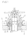
- Fig. 1 is a sectional view of an agitating granulation machine of the invention, near the agitating blade.
- Fig. 2 is a sectional view of an agitating granulation machine of the invention, near the crushing blade.
- Fig. 3 (a) is a sectional view showing the entire structure of the agitating granulation machine, and (b) shows a plan view and a sectional view of line A-A thereof.
- Fig. 4 is a sectional view of a conventional agitating granulation machine, near the agitating blade.
- Fig. 5 is a sectional view of a conventional agitating granulation machine, near the crushing blade.
- Fig. 1 is a sectional view around the agitating blade 3.
- the agitating blade 3 is composed, same as in the prior art, by penetrating a rotary shaft 7 covered with a sleeve 28 into a bottom wall 25 of the processing container 1 and a bush 27 affixed in the bottom wall 25, and attaching a hub 6 to the front end of this rotary shaft 7.
- the bush 27 is formed thinner than the conventional one, in a truncated conical form, and its upper surface has a plurality of outlets 10 of the first air feed pipe 9 communicating with an air supply source (not shown) outside the machine.
- the hub 6 has a dent 30 and an annular protrusion 31 in its lower surface.
- the hub 6 is tightened and fixed to the top end portion of the rotary shaft 7 by a locknut 8 while allowing the dent 30 and bush 27 to fit loosely, and at this time a first air passage 12 is formed in the gap between the hub 6 and bush 27.
- the first air passage 12 is composed of an annular passage 32 formed on the lower surface of the hub 6 and the upper surface of the bush 27, a tapered passage 33 formed on the inner surface of the annular protrusion 31 and the side surface of the bush 27, and an annular first discharge port 13 formed on the front end portion of the annular protrusion 31 and the bottom wall 25 of the processing container 1.
- the annular passage 32 may be formed relatively wide.
- the tapered passage 33 is gradually tapered downward.
- the apparatus of the invention is almost free of sharply bent parts in the first air passage 12.
- the material powder or dust particles in the air may hardly start within the passage 12, which makes it possible to agitate and granulate always in clean state.
- the flow resistance of the fluid is decreased, and cleaning job or draining and drying job after cleaning in the passage 12 may be done easily, and therefore drain circuit for discharging the cleaning water stagnant in the passage 12 is not required, so that the structure may be simplified.
- a seal ring 48 for sealing between the hub 6 and sleeve 28 is fitted on the upper surface of the hub 6.
- Fig. 2 shows a sectional view around the crushing blade 4.
- the rotary shaft 15 penetrating into the side wall 35 of the processing container 1 is covered with a sleeve 36 affixed to the side wall 35.
- This sleeve 36 is composed by forming a dent 37 and a flange 38 on the top end portion of the rotor 16 side, and the bottom of the dent 37 has one or plurality of outlets 21 of a second air feed pipe 20 communicating with an external air supply source (not shown).
- the rotor 16 has a flange 40 and a base 41 in a truncated conical form, and the peripheral part of the flange 40 is bent and formed at the processing container 1 side in the axial direction to compose an annular protrusion 42.
- the base 41 meanwhile, has a proper axial length so as to produce a relatively large gap against the bottom of the dent 37 when buried into the dent 37.
- the rotor 16 is inserted into the rotary shaft 15 while allowing the base 41 and dent 37 to fit loosely, and is tightened and fixed to the rotary shaft 15 with locknut 19 properly by away of plural collars 17 and crushing edges 18.
- a second air passage 22 is formed in the gap between the rotor 16 and sleeve 36.
- the second air passage 22 comprises an annular passage 44 constructed of the bottom of the dent 37 and the surface of its confronting rotor 16, a tapered passage 45 constructed of the side surface of the base 41 and the inside surface of the dent 37, a discharge passage 46 constructed of the flange 40, protrusion 42 and flange 38, and an annular second discharge port 23 constructed of the front end portion of the protrusion 42 and the side wall 35.
- the base 41 is formed to as to widen the gap between the base 41 of the rotor 16 and the bottom of the dent 37, the annular passage 44 is relatively wide, and since the base 41 is in a truncated conical form, the tapered passage 45 is tapered gradually toward the front end direction of the crushing blade 4.
- a seal ring 49 for sealing the sleeve 36 and rotary shaft 15 is fitted to the dent side of the sleeve 36 to make it easier to check the seal ring 49 visually and replace it. That is, these jobs can be done easily from inside of the processing container 1 by detaching the locknut 19, crushing edge 18, collar 17, and rotor 16.
Landscapes
- Chemical & Material Sciences (AREA)
- Organic Chemistry (AREA)
- Chemical Kinetics & Catalysis (AREA)
- Accessories For Mixers (AREA)
- Glanulating (AREA)
- Crushing And Pulverization Processes (AREA)
Applications Claiming Priority (2)
| Application Number | Priority Date | Filing Date | Title |
|---|---|---|---|
| JP295417/91 | 1991-10-24 | ||
| JP29541791A JP3162135B2 (ja) | 1991-10-24 | 1991-11-12 | 攪拌造粒装置 |
Publications (1)
| Publication Number | Publication Date |
|---|---|
| EP0538975A1 true EP0538975A1 (fr) | 1993-04-28 |
Family
ID=17820339
Family Applications (1)
| Application Number | Title | Priority Date | Filing Date |
|---|---|---|---|
| EP92301684A Withdrawn EP0538975A1 (fr) | 1991-10-24 | 1992-02-27 | Granulateur-mélangeur |
Country Status (2)
| Country | Link |
|---|---|
| EP (1) | EP0538975A1 (fr) |
| JP (1) | JP3162135B2 (fr) |
Cited By (5)
| Publication number | Priority date | Publication date | Assignee | Title |
|---|---|---|---|---|
| WO1994025147A1 (fr) * | 1993-05-04 | 1994-11-10 | Pro-Distribution Holding S.A. | Palier pour melangeur a vis sans fin |
| WO1996004984A1 (fr) * | 1994-08-12 | 1996-02-22 | Abs Pump Center Gmbh | Agitateur |
| EP0809940A3 (fr) * | 1996-05-31 | 1999-06-02 | Degussa Aktiengesellschaft | Procédé de fabrication d'un additif fourrager pour animaux à base d'un moût de fermentation |
| WO2015033145A1 (fr) * | 2013-09-06 | 2015-03-12 | Matcon Ltd | Système d'étanchéité |
| CN116159480A (zh) * | 2022-12-07 | 2023-05-26 | 湖南宝东农牧科技股份有限公司 | 一种饲料加工环模制粒设备 |
Families Citing this family (6)
| Publication number | Priority date | Publication date | Assignee | Title |
|---|---|---|---|---|
| JP5067545B2 (ja) * | 2007-09-20 | 2012-11-07 | 国立大学法人宇都宮大学 | コーティング方法及び装置 |
| JP5618789B2 (ja) * | 2010-11-30 | 2014-11-05 | 株式会社アーステクニカ | 減圧乾燥機及び運転制御方法 |
| JP2016077947A (ja) * | 2014-10-14 | 2016-05-16 | 株式会社パウレック | 粉粒体処理装置の付着物除去方法 |
| JP2016123912A (ja) * | 2014-12-26 | 2016-07-11 | 株式会社パウレック | 粉粒体の処理装置 |
| CN108554312B (zh) * | 2018-01-22 | 2024-11-01 | 江阴市龙昌机械制造有限公司 | 湿法制粒机 |
| JP7257673B2 (ja) * | 2019-06-26 | 2023-04-14 | 株式会社パウレック | 撹拌混合造粒装置 |
Citations (4)
| Publication number | Priority date | Publication date | Assignee | Title |
|---|---|---|---|---|
| DE2257188A1 (de) * | 1972-11-22 | 1974-06-06 | Schlecht Karl | Stopfbuchsenanordnung fuer betonmischkessel |
| FR2292566A1 (fr) * | 1974-11-29 | 1976-06-25 | Rheinstahl Ag | Procede et dispositif pour la preparation de melanges a base de chlorure de polyvinyle |
| CH615739A5 (en) * | 1976-07-08 | 1980-02-15 | Chemap Ag | Gas-sealed shaft sealing for a fermenter |
| EP0384391A2 (fr) * | 1989-02-21 | 1990-08-29 | Kureha Chemical Industry Co., Ltd. | Boîte en carton distributrice de matériau en feuille embobiné en rouleaux |
-
1991
- 1991-11-12 JP JP29541791A patent/JP3162135B2/ja not_active Expired - Lifetime
-
1992
- 1992-02-27 EP EP92301684A patent/EP0538975A1/fr not_active Withdrawn
Patent Citations (4)
| Publication number | Priority date | Publication date | Assignee | Title |
|---|---|---|---|---|
| DE2257188A1 (de) * | 1972-11-22 | 1974-06-06 | Schlecht Karl | Stopfbuchsenanordnung fuer betonmischkessel |
| FR2292566A1 (fr) * | 1974-11-29 | 1976-06-25 | Rheinstahl Ag | Procede et dispositif pour la preparation de melanges a base de chlorure de polyvinyle |
| CH615739A5 (en) * | 1976-07-08 | 1980-02-15 | Chemap Ag | Gas-sealed shaft sealing for a fermenter |
| EP0384391A2 (fr) * | 1989-02-21 | 1990-08-29 | Kureha Chemical Industry Co., Ltd. | Boîte en carton distributrice de matériau en feuille embobiné en rouleaux |
Cited By (6)
| Publication number | Priority date | Publication date | Assignee | Title |
|---|---|---|---|---|
| WO1994025147A1 (fr) * | 1993-05-04 | 1994-11-10 | Pro-Distribution Holding S.A. | Palier pour melangeur a vis sans fin |
| WO1996004984A1 (fr) * | 1994-08-12 | 1996-02-22 | Abs Pump Center Gmbh | Agitateur |
| EP0809940A3 (fr) * | 1996-05-31 | 1999-06-02 | Degussa Aktiengesellschaft | Procédé de fabrication d'un additif fourrager pour animaux à base d'un moût de fermentation |
| WO2015033145A1 (fr) * | 2013-09-06 | 2015-03-12 | Matcon Ltd | Système d'étanchéité |
| US10240676B2 (en) | 2013-09-06 | 2019-03-26 | Matcon Ltd. | Seal system |
| CN116159480A (zh) * | 2022-12-07 | 2023-05-26 | 湖南宝东农牧科技股份有限公司 | 一种饲料加工环模制粒设备 |
Also Published As
| Publication number | Publication date |
|---|---|
| JP3162135B2 (ja) | 2001-04-25 |
| JPH05115766A (ja) | 1993-05-14 |
Similar Documents
| Publication | Publication Date | Title |
|---|---|---|
| EP0538975A1 (fr) | Granulateur-mélangeur | |
| KR100472620B1 (ko) | 교반기 | |
| KR100927949B1 (ko) | 바스켓 밀 | |
| JP5882018B2 (ja) | 粉体と液体との連続混合装置 | |
| JPS6243731B2 (fr) | ||
| JP4451965B2 (ja) | パイプラインビ−ズミル | |
| US6029853A (en) | Dispersing method, dispersing apparatus and dispersing system having dispersing apparatus | |
| KR100560356B1 (ko) | 분립체 공급기 | |
| CA2110508C (fr) | Dispositif servant a disperser, mettre en suspension ou emulsifier des gaz, des liquides ou d'autres substances solides a ecoulement facile | |
| US5393138A (en) | Apparatus for mixing foundry mould substances | |
| KR200472745Y1 (ko) | 오거피더에서 발생되는 분진을 방지하기 위한 씰링장치 | |
| EP0468427A1 (fr) | Pulvérisateur | |
| US7020984B2 (en) | Device for feeding a drying gas to a mixing granulator | |
| JP4163652B2 (ja) | 粉体/液体連続混合装置 | |
| SE505871C2 (sv) | Blandningsanordning för blandning av svartlut från cellulosatillverkning med aska från rökgaser åstadkommen vid förbränning av svartlut | |
| US5518191A (en) | Agitator mill | |
| US5300317A (en) | Process for covering solid particles in powder form with a material which is solid or of high viscosity at room temperature | |
| CN1939581B (zh) | 粉体/液体连续混合装置 | |
| US3415494A (en) | Liquid addition mixer | |
| KR102492962B1 (ko) | Wip 랙을 이용한 교반기 청소 시스템 | |
| JP3559932B2 (ja) | 攪拌装置 | |
| RU2024290C1 (ru) | Устройство для гранулирования суспензий | |
| KR20240050340A (ko) | 분산 유닛 | |
| JP2001300447A (ja) | 粉粒体処理装置及びその洗浄方法 | |
| JP2005199125A (ja) | メディア攪拌ミル |
Legal Events
| Date | Code | Title | Description |
|---|---|---|---|
| PUAI | Public reference made under article 153(3) epc to a published international application that has entered the european phase |
Free format text: ORIGINAL CODE: 0009012 |
|
| AK | Designated contracting states |
Kind code of ref document: A1 Designated state(s): CH DE FR GB IT LI |
|
| 17P | Request for examination filed |
Effective date: 19930817 |
|
| 18D | Application deemed to be withdrawn |
Effective date: 19940901 |