EP0539735B1 - Procédé et dispositif d'exposition de récipients mobiles à un rayonnement laser - Google Patents
Procédé et dispositif d'exposition de récipients mobiles à un rayonnement laser Download PDFInfo
- Publication number
- EP0539735B1 EP0539735B1 EP92116503A EP92116503A EP0539735B1 EP 0539735 B1 EP0539735 B1 EP 0539735B1 EP 92116503 A EP92116503 A EP 92116503A EP 92116503 A EP92116503 A EP 92116503A EP 0539735 B1 EP0539735 B1 EP 0539735B1
- Authority
- EP
- European Patent Office
- Prior art keywords
- carousel
- mirror
- laser beam
- bottle
- bottles
- Prior art date
- Legal status (The legal status is an assumption and is not a legal conclusion. Google has not performed a legal analysis and makes no representation as to the accuracy of the status listed.)
- Expired - Lifetime
Links
Images
Classifications
-
- B—PERFORMING OPERATIONS; TRANSPORTING
- B07—SEPARATING SOLIDS FROM SOLIDS; SORTING
- B07C—POSTAL SORTING; SORTING INDIVIDUAL ARTICLES, OR BULK MATERIAL FIT TO BE SORTED PIECE-MEAL, e.g. BY PICKING
- B07C5/00—Sorting according to a characteristic or feature of the articles or material being sorted, e.g. by control effected by devices which detect or measure such characteristic or feature; Sorting by manually actuated devices, e.g. switches
- B07C5/04—Sorting according to size
- B07C5/12—Sorting according to size characterised by the application to particular articles, not otherwise provided for
- B07C5/122—Sorting according to size characterised by the application to particular articles, not otherwise provided for for bottles, ampoules, jars and other glassware
-
- B—PERFORMING OPERATIONS; TRANSPORTING
- B07—SEPARATING SOLIDS FROM SOLIDS; SORTING
- B07C—POSTAL SORTING; SORTING INDIVIDUAL ARTICLES, OR BULK MATERIAL FIT TO BE SORTED PIECE-MEAL, e.g. BY PICKING
- B07C5/00—Sorting according to a characteristic or feature of the articles or material being sorted, e.g. by control effected by devices which detect or measure such characteristic or feature; Sorting by manually actuated devices, e.g. switches
- B07C5/34—Sorting according to other particular properties
- B07C5/3412—Sorting according to other particular properties according to a code applied to the object which indicates a property of the object, e.g. quality class, contents or incorrect indication
-
- G—PHYSICS
- G06—COMPUTING OR CALCULATING; COUNTING
- G06K—GRAPHICAL DATA READING; PRESENTATION OF DATA; RECORD CARRIERS; HANDLING RECORD CARRIERS
- G06K1/00—Methods or arrangements for marking the record carrier in digital fashion
- G06K1/12—Methods or arrangements for marking the record carrier in digital fashion otherwise than by punching
- G06K1/126—Methods or arrangements for marking the record carrier in digital fashion otherwise than by punching by photographic or thermographic registration
Definitions
- the invention relates to a method according to claim 1 and a device according to claim 3.
- the inspection particularly includes checking the bottle for damage and / or reading one or more code symbols on the bottle. As a rule, the inspection machine applies at least one further code symbol. This application or melting of the code symbol and, if appropriate, the reading of code symbols take place by means of at least one laser beam, which is generally directed onto the bottle at a desired, predetermined location. Damage can also be checked using laser beams.
- Known systems for the inspection and / or coding of PET bottles with laser radiation are characterized on the one hand by a static beam guidance.
- the parts to be processed are positioned in front of the beam in such a way that the coding area is acted on by the beam.
- the transport movement must be interrupted for the duration of the coding process or the coding must be carried out in the shortest possible time.
- the disadvantages of this concept are the high accelerations and low productivity of the laser and machine.
- a device for applying a code using a laser beam in which no tracking of the object is provided, but in which a movable mirror deflects the laser beam at times in order to apply the beam to the object to be marked through more than one mask.
- the invention is therefore based on the object of processing and / or measuring or inspecting containers, but in particular PET bottles, as they pass through the inspection machine by means of a laser beam, this being done with the highest possible cadence and productivity.
- the method is preferably used for PET bottles in order to apply code symbols to these bottles.
- the mask is located within the hollow shaft in the beam path, and a second deflecting mirror is located beneath it, which deflects the beam radially 90 °. If this deflecting mirror is firmly mounted on the axis, the laser beam will maintain a constant position with respect to the carousel axis, regardless of the speed of rotation of the carousel.
- a lens or a parabolic mirror can be arranged immediately behind the second mirror in order to image the mask on the bottle.
- This arrangement is expediently supplemented by a further deflecting mirror opposite the bottle holder, with which the fine positioning of the beam takes place.
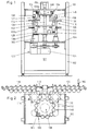
- FIGS. 1 and 2 An inspection machine known per se is shown in FIGS. 1 and 2, which will first be briefly explained for a better understanding of the following exemplary embodiments of the invention. This special inspection machine is only shown as an example and for a better understanding of FIGS. 3 to 5; the invention can easily be applied to other inspection machines.
- the machine is generally designated 101 in FIG. 1. It has a frame 102 with an upper support plate 103 and a lower support plate 104, between which a carousel device, generally designated 106, is fastened.
- the carousel device 106 has a central carousel 108 with twelve receiving devices 110 for bottles 112 and two smaller carousels 114, 116, each with eight receiving devices on.
- the carousel device 106 is part of a conveying device with which the bottles 112 are moved into a detection station 130 for checking and reading codes and an identification station 140 for writing codes, which is described in more detail below.
- the two smaller carousels 114, 116 in conjunction with two screw conveyors 118, 120, convey the bottles 112 into and out of the device 101.
- a common drive system 122 is fastened, which comprises a geared motor 124, which in detail Toothed belt pulleys and toothed belts, not specified, drives the carousel device 106 and the screw conveyors 118, 120.
- the central carousel 108 consists of an upper main carousel 108a, a central main carousel 108b and a lower main carousel 108c, which are fastened on a common shaft 109.
- the receptacles 110 consist of twelve recesses semicircular in cross-section on the central main carousel 108b, twelve heads 126 provided on the upper main carousel 108a (only two are visible in FIG. 1) and twelve rotatable seats 128 provided on the lower main carousel 108c for receiving, clamping or placing the bottles 112. Each head 126 is fastened to the upper main carousel 108a in a vertically movable manner with a curved track.
- the course or the shape of the curved path is selected such that the head 126 is arranged in the area of the carousel 114 at a distance above the bottle mouth, that during the movement of the bottle 112 into the detection station 130 the bottle mouth is lowered and at least until the bottle is reached Marking station 140 remains lowered and is finally raised again from the bottle and moved back to its original height at which it is at a distance from the bottle mouth.
- the bottle 112 After the bottle 112 has passed the screw conveyor 118 and the carousel 114 at the inlet of the device, it is clamped vertically in the holding devices 110 of the central carousel 108 by lowering the head 126. After clamping, some time is available to let vibrations subside. Then the bottle 112 passes the detection station 130, where the bottle is inspected and a code already on the bottle is read. This information is transmitted to a main controller and from here to a carousel microcontroller. The carousel microcontroller drives the stepper motors 158 to place the bottle 112 in the position where it can be identified with a new code symbol. After the new code symbol has been applied, the bottle is released by lifting the head 126. The carousel 116 and the screw conveyor 120 at the outlet of the device 101 convey the bottle 112 out of the device 101.
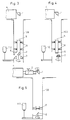
- FIG. 3 schematically shows a part of the carousel with the axis 109 of the carousel designed as a hollow shaft and only one bottle 112 shown in the carousel as an example, which rotates around the hollow shaft and which in the example shown is to be provided with a code.
- the beam is reflected exactly in the carousel axis by means of deflecting mirror 1.
- deflecting mirror 2 which is fixed centrally in the axis and remains directed at this point when the carousel is rotated.
- the laser 4 is firmly mounted on the machine, so that the first one available as standard Deflecting mirror 1 deflects the beam centrally into the carousel axis 109 designed as a hollow shaft.
- the mask 5 with the pattern of the code and a second deflecting mirror 2, which deflects the beam radially by 90 °, is located in the beam path within the hollow shaft. If this deflecting mirror 2 is fixedly mounted on the axis or if the mirror is moved synchronously with the hollow shaft 109, the laser beam will maintain a constant position with respect to the carousel axis, regardless of the speed of rotation of the carousel.
- a lens or a parabolic mirror 6 can be arranged as a focusing mirror in order to image the mask on the bottle.
- the image of the mask is burned into the PET bottle material by the laser beam.
- This arrangement is expediently supplemented by a further deflecting mirror 3 opposite each bottle holder (pocket), where a window is also provided in the hollow shaft, with which the beam is finely positioned.
- the mirror 2 or the beam guide 5, 2 and 6 is quickly positioned to the next window or deflecting mirror 3 in order to process the next bottle.
- the last deflecting mirrors 3 are fixedly positioned in the circumference of the hollow shaft, in this case the adjustability of two tilt angles is sufficient.
- the imaging optics After taking a bottle into the main carousel, it is set in constant rotation by the base plate. The imaging optics are positioned on this bottle and follow the movement of the carousel. A code can now be marked during the rotation. After completing the marking process, the optics must be positioned on the following bottle.
- the polygon 7 contains the same number of mirror surfaces as the number of bits in the coding. Through each of these mirror surfaces, the beam that is incident vertically into the carousel axis is deflected onto the coding surface of the bottle. As the bottle moves with the carousel during coding (rotating), it is necessary to carry the jet with it.
- the polygon must rotate by the angle ⁇ p so that the next mirror surface offset by the angle ⁇ k is aligned.
- This speed ratio of carousel and polygon is independent of the speed.
- the coding pulses are thus aligned with the axis of rotation of the bottle, the distance between successive codes is then only dependent on the speed of the bottle itself.
- the polygon 7 is a special case of polygons whose common characteristic is that their mirror surfaces are each offset by an equal angle, i.e. the mirror surfaces form tangents to a spiral. Optical inspections are also possible with such polygons. If the number of mirror surfaces is increased, a beam can be tracked quasi-continuously to an object on the carousel. The length of the tracking section is determined by the sum of the individual offset angles.
- FIG. 5 A further embodiment is shown in FIG. 5, the same reference numerals denoting the same components as above.
- the mask 5 is arranged between the laser 4 and the first mirror 1.
- the imaging optics 6 are fixed while the mirrors 1 and 2 are moved synchronously with the bottle 112.
- the aim of this variant is the rotation of the beam relative to the mask and the rotation of the image to eliminate on the bottle. This eliminates the need to rotate the mask and lens with the carousel.
- the mask is mounted in front of the first deflecting mirror. With the first mirror, the mask image is rotated and deflected 90 °. The beam must be centered in the mirror axis of rotation. At a corresponding distance from the mask, the lens is centered in the beam or. Carousel axis fixed (only linear focus adjustment). A second deflecting mirror is rotatably mounted directly under the lens, which directs the focused beam onto the bottle.
- Angle change only set one axis of the lower deflecting mirror.
- the optics inside the hollow shaft are all in the center, best design for dust / water protection.
Landscapes
- Physics & Mathematics (AREA)
- General Physics & Mathematics (AREA)
- Engineering & Computer Science (AREA)
- Theoretical Computer Science (AREA)
- Sorting Of Articles (AREA)
- Investigating Materials By The Use Of Optical Means Adapted For Particular Applications (AREA)
- Wrapping Of Specific Fragile Articles (AREA)
- Specific Conveyance Elements (AREA)
- Laser Beam Processing (AREA)
Claims (7)
- Procédé d'exposition de récipients (112) déplacés par une installation de transport, à au moins un faisceau laser en vue de l'inspection et/ou du traitement des récipients, le faisceau laser étant guidé par une disposition de miroirs (1,2,3; 1,7; 1,2) fixes et/ou mobiles par rapport à l'installation de transport, pour être déplacé de manière synchrone avec un des récipients (112) pendant au moins un tronçon du trajet de transport, et exposer celui-ci, dans lequel une installation de transport comprenant un caroussel est prévue pour les récipients (112), le caroussel comprenant un arbre creux central (109), dans lequel le faisceau laser d'une source de lumière laser (4) est guidé par un premier miroir (1) et dans laquelle à l'intérieur de l'arbre creux est prévu un dispositif de guidage de faisceau (2,3;5,6,7;2,6) mobile de façon synchrone avec le récipient (112).
- Procédé selon la revendication 1, caractérisé en ce qu'au moins un symbole codé est appliqué par le faisceau laser au récipient qui est formé d'une bouteille en polyéthylène téréphtalate.
- Dispositif d'exposition de bouteilles en polyéthylène-thérephtalate (112) déplacées par une installation de transport, à au moins un faisceau laser en vue de l'inspection et/ou du traitement des bouteilles, le faisceau laser étant guidé par une disposition de miroirs (1,2,3; 1,7;1,2) fixes et/ou mobiles par rapport à l'installation de transport, pour être déplacé de manière synchrone avec une des bouteilles (112) pendant au moins un tronçon du trajet de transport, et exposer celui-ci, dans lequel une installation de transport comprenant un caroussel est prévue pour les bouteilles (112), le caroussel comprenant un arbre creux central (109), dans lequel le faisceau laser d'une source de lumière laser (4) est guidé par un premier miroir (1) et dans laquelle à l'intérieur de l'arbre creux est prévu un dispositif de guidage de faisceau (2,3,5,6;5,6,7;2,6) mobile de façon synchrone avec la bouteille (112);
- Dispositif selon la revendication 3, caractérisé en ce que le dispositif de guidage de faisceau comprend un masque (5), un deuxième miroir (2) et un miroir de focalisation (6).
- Dispositif selon la revendication 4, caractérisé en ce que le faisceau laser sortant du dispositif de guidage de faisceau peut être dévié de l'arbre creux (109) en direction de la bouteille (112) par un miroir de déviation (3) qui est associé à un support de la bouteille.
- Dispositif selon la revendication 3, caractérisé en ce que le dispositif de guidage de faisceau comprend un miroir polygonal rotatif (7) qui est exposé à un faisceau laser qui est guidé à travers un masque (5) et une lentille de focalisation (6).
- Dispositif selon la revendication 3, caractérisé en ce que le dispositif de guidage de faisceau comprend un deuxième miroir (2), un masque (5) et une lentille de focalisation (6) et que le faisceau laser peut être dévié vers la bouteille (112) par le deuxième miroir.
Applications Claiming Priority (2)
| Application Number | Priority Date | Filing Date | Title |
|---|---|---|---|
| CH3199/91A CH683288A5 (de) | 1991-11-01 | 1991-11-01 | Verfahren und Vorrichtung zur Beaufschlagung bewegter Gebinde mit einem Laserstrahl. |
| CH3199/91 | 1991-11-01 |
Publications (2)
| Publication Number | Publication Date |
|---|---|
| EP0539735A1 EP0539735A1 (fr) | 1993-05-05 |
| EP0539735B1 true EP0539735B1 (fr) | 1996-03-06 |
Family
ID=4250800
Family Applications (1)
| Application Number | Title | Priority Date | Filing Date |
|---|---|---|---|
| EP92116503A Expired - Lifetime EP0539735B1 (fr) | 1991-11-01 | 1992-09-26 | Procédé et dispositif d'exposition de récipients mobiles à un rayonnement laser |
Country Status (6)
| Country | Link |
|---|---|
| US (1) | US5315108A (fr) |
| EP (1) | EP0539735B1 (fr) |
| AT (1) | ATE134909T1 (fr) |
| CH (1) | CH683288A5 (fr) |
| DE (1) | DE59205574D1 (fr) |
| MX (1) | MX9206266A (fr) |
Cited By (2)
| Publication number | Priority date | Publication date | Assignee | Title |
|---|---|---|---|---|
| US6715273B2 (en) | 2001-09-22 | 2004-04-06 | Deere & Company | Stalk divider |
| EP4714662A1 (fr) * | 2024-09-17 | 2026-03-25 | KHS GmbH | Dispositif et procédé de marquage de récipients, machine de codage laser et installation de fabrication et/ou de traitement de récipients |
Families Citing this family (18)
| Publication number | Priority date | Publication date | Assignee | Title |
|---|---|---|---|---|
| WO1994025186A1 (fr) * | 1993-04-30 | 1994-11-10 | Robert Massen | Procede et dispositif permettant de trier des materiaux |
| DE4314396A1 (de) * | 1993-04-30 | 1994-11-03 | Robert Prof Dr Ing Massen | Optische Sortierung von Kunststoffen |
| US5755335A (en) * | 1995-07-26 | 1998-05-26 | Steinmetz Machine Works, Inc. | Apparatus and method for centralized indexed inspection and rejection of products |
| DE19736732A1 (de) * | 1997-08-22 | 1999-03-11 | Lzh Laserzentrum Hannover Ev | Einrichtung und Verfahren zur Bearbeitung eines Werkstückes mittels elektromagnetischer Strahlung sowie Spiegel zur Reflexion von elektromagnetischer Strahlung, insbesondere von Laserlicht |
| US6926487B1 (en) * | 1998-04-28 | 2005-08-09 | Rexam Ab | Method and apparatus for manufacturing marked articles to be included in cans |
| US6706995B2 (en) * | 1998-07-16 | 2004-03-16 | Ball Corporation | Laser light marking of a container portion |
| US6080958A (en) | 1998-07-16 | 2000-06-27 | Ball Corporation | Method and apparatus for marking containers using laser light |
| WO2000035678A1 (fr) * | 1998-12-16 | 2000-06-22 | The Domino Corporation | Procede et appareil servant a produire des marques et des codes sur des emballages en pet |
| DE19911827A1 (de) | 1999-03-17 | 2000-09-28 | Deere & Co | Halmteiler |
| US6809288B2 (en) * | 2001-05-23 | 2004-10-26 | Osmotica Corp. | Laser drilling system and method |
| PT1295818E (pt) * | 2001-09-20 | 2006-06-30 | Simonnazzi S P A | Transportador de garrafas equipado com mecanismos de accionamento montados no topo |
| US7067323B2 (en) * | 2003-10-15 | 2006-06-27 | Lighthouse Instruments, Llc | System and method for automated headspace analysis |
| DE102008028376A1 (de) | 2008-06-13 | 2009-12-17 | Krones Ag | Vorrichtung und Verfahren zum Kennzeichnen von Kunststoffbehältnissen |
| DE102008030868A1 (de) * | 2008-06-30 | 2009-12-31 | Krones Ag | Vorrichtung zum Beschriften von Behältnissen |
| DE102013103310A1 (de) | 2013-04-03 | 2014-10-09 | Khs Gmbh | Transportvorrichtung für Behälterbehandlungsmaschinen |
| DE102013206667A1 (de) * | 2013-04-15 | 2014-10-16 | Krones Aktiengesellschaft | Behälterbehandlungsmaschine und Tischplatten für Behälterbehandlungsmaschinen |
| US10421111B2 (en) | 2015-04-17 | 2019-09-24 | Ball Corporation | Method and apparatus for controlling an operation performed on a continuous sheet of material |
| RU2670129C1 (ru) | 2015-04-17 | 2018-10-18 | Бол Корпорейшн | Способ и устройство для регулирования скорости непрерывного листа материала |
Family Cites Families (6)
| Publication number | Priority date | Publication date | Assignee | Title |
|---|---|---|---|---|
| SE385988B (sv) * | 1973-06-21 | 1976-07-26 | Platmanufaktur Ab | Identifieringsanordning for formnummerlesning pa maskinformade produkter exv. plast- eller glasprodukter |
| CA1042530A (fr) * | 1974-05-06 | 1978-11-14 | Ross L. Hobler | Methode et appareil pour identifier une bouteille |
| GB2134449A (en) * | 1983-02-01 | 1984-08-15 | Laserprint | Laser printing apparatus |
| FR2558259B1 (fr) * | 1984-01-17 | 1986-12-12 | Saint Gobain Cinematique Contr | Emetteur a balayage pour l'inspection optique d'articles transparents |
| CH676644A5 (fr) * | 1988-08-09 | 1991-02-15 | Elpatronic Ag | |
| US4967070A (en) * | 1989-07-19 | 1990-10-30 | Owens-Brockway Glass Container Inc. | Indentification of a molded container with its mold of origin |
-
1991
- 1991-11-01 CH CH3199/91A patent/CH683288A5/de not_active IP Right Cessation
-
1992
- 1992-09-26 DE DE59205574T patent/DE59205574D1/de not_active Expired - Fee Related
- 1992-09-26 EP EP92116503A patent/EP0539735B1/fr not_active Expired - Lifetime
- 1992-09-26 AT AT92116503T patent/ATE134909T1/de not_active IP Right Cessation
- 1992-10-15 US US07/962,317 patent/US5315108A/en not_active Expired - Fee Related
- 1992-10-30 MX MX9206266A patent/MX9206266A/es unknown
Cited By (2)
| Publication number | Priority date | Publication date | Assignee | Title |
|---|---|---|---|---|
| US6715273B2 (en) | 2001-09-22 | 2004-04-06 | Deere & Company | Stalk divider |
| EP4714662A1 (fr) * | 2024-09-17 | 2026-03-25 | KHS GmbH | Dispositif et procédé de marquage de récipients, machine de codage laser et installation de fabrication et/ou de traitement de récipients |
Also Published As
| Publication number | Publication date |
|---|---|
| US5315108A (en) | 1994-05-24 |
| EP0539735A1 (fr) | 1993-05-05 |
| DE59205574D1 (de) | 1996-04-11 |
| ATE134909T1 (de) | 1996-03-15 |
| CH683288A5 (de) | 1994-02-15 |
| MX9206266A (es) | 1993-08-01 |
Similar Documents
| Publication | Publication Date | Title |
|---|---|---|
| EP0539735B1 (fr) | Procédé et dispositif d'exposition de récipients mobiles à un rayonnement laser | |
| EP1553405B1 (fr) | Machine de contrôle | |
| EP0433666B1 (fr) | Appareil d'inspection tridimensionnelle de corps creux | |
| DE2429160C2 (de) | Verfahren und Vorrichtung zum Identifizieren maschinengeformter Formlinge | |
| EP0338376B1 (fr) | Procédé de lecture optique de marques sur des objets et dispositif pour sa mise en oeuvre | |
| DE2256736A1 (de) | Verfahren zur automatischen oberflaechenprofilmessung und vorrichtung zur durchfuehrung des verfahrens | |
| EP0682991A2 (fr) | Machine automatique pour le tri, respectivement la classification d'après la forme et la couleur, de petits produits de l'industrie pharmaceutique et des friandises | |
| DE2014448C3 (de) | Vorrichtung zur Behandlung von Werk stucken mittels Laserenergie | |
| DE10146820A1 (de) | Dekoriervorrichtung und Verfahren zum Dekorieren von Oberflächen | |
| DE60224623T2 (de) | Wanddickenmessung eines transparenten Behälters mit einem Lichtfächer | |
| DE102017218814B4 (de) | Beschriftungseinrichtung und Verfahren zur Beschriftung eines Werkstücks | |
| DE69015908T2 (de) | Identifikation eines gegossenen Behälters mit seiner Ursprungsform. | |
| DE2338295C2 (de) | Vorrichtung zum Feststellen von Fehlern auf gegenüberliegenden Flächen einer im wesentlichen ebenen Bahn | |
| DE4313796A1 (de) | Laserbearbeitungsvorrichtung | |
| DE68917158T2 (de) | Vorrichtung zur Drehung eines Lichtbildes und optisches System zur Lichtstrahlbündelung auf einem Aufzeichnungsmittel. | |
| EP0287018B1 (fr) | Etiqueteuse avec contrôle d'impression | |
| EP1804055A1 (fr) | Dispositif destiné à inspecter des étiquettes situées sur des récipients | |
| DE3307484C2 (de) | Optisch-mechanischer Abtaster | |
| DE2556395A1 (de) | Verfahren und vorrichtung zur ueberpruefung eines glasbandes, welches in einer vorgegebenen richtung bewegt wird | |
| DE1135201B (de) | Kontrolleinrichtung zur Feststellung von Fremdkoerpern in einem durch-scheinenden Behaelter mit Mitteln zur Beleuchtung einer zu kontrollierenden Zone des Behaelters | |
| DE3784989T2 (de) | Verfahren und vorrichtung zum pruefen der oberflaeche von halbleiterwafern mittels laserabtastung. | |
| DE3242002C2 (fr) | ||
| DE3220948A1 (de) | Abtastvorrichtung | |
| DE69222011T2 (de) | Röntgenanalysegerät | |
| DE4024546C1 (fr) |
Legal Events
| Date | Code | Title | Description |
|---|---|---|---|
| PUAI | Public reference made under article 153(3) epc to a published international application that has entered the european phase |
Free format text: ORIGINAL CODE: 0009012 |
|
| 17P | Request for examination filed |
Effective date: 19930123 |
|
| AK | Designated contracting states |
Kind code of ref document: A1 Designated state(s): AT DE NL SE |
|
| 17Q | First examination report despatched |
Effective date: 19941125 |
|
| RAP1 | Party data changed (applicant data changed or rights of an application transferred) |
Owner name: ELPATRONIC AG |
|
| GRAA | (expected) grant |
Free format text: ORIGINAL CODE: 0009210 |
|
| AK | Designated contracting states |
Kind code of ref document: B1 Designated state(s): AT DE NL SE |
|
| REF | Corresponds to: |
Ref document number: 134909 Country of ref document: AT Date of ref document: 19960315 Kind code of ref document: T |
|
| REF | Corresponds to: |
Ref document number: 59205574 Country of ref document: DE Date of ref document: 19960411 |
|
| PG25 | Lapsed in a contracting state [announced via postgrant information from national office to epo] |
Ref country code: AT Effective date: 19960926 |
|
| PLBE | No opposition filed within time limit |
Free format text: ORIGINAL CODE: 0009261 |
|
| 26N | No opposition filed | ||
| PGFP | Annual fee paid to national office [announced via postgrant information from national office to epo] |
Ref country code: DE Payment date: 19970919 Year of fee payment: 6 |
|
| PGFP | Annual fee paid to national office [announced via postgrant information from national office to epo] |
Ref country code: SE Payment date: 19970925 Year of fee payment: 6 |
|
| PGFP | Annual fee paid to national office [announced via postgrant information from national office to epo] |
Ref country code: NL Payment date: 19970929 Year of fee payment: 6 |
|
| PG25 | Lapsed in a contracting state [announced via postgrant information from national office to epo] |
Ref country code: SE Free format text: LAPSE BECAUSE OF NON-PAYMENT OF DUE FEES Effective date: 19980927 |
|
| PG25 | Lapsed in a contracting state [announced via postgrant information from national office to epo] |
Ref country code: NL Free format text: LAPSE BECAUSE OF NON-PAYMENT OF DUE FEES Effective date: 19990401 |
|
| EUG | Se: european patent has lapsed |
Ref document number: 92116503.1 |
|
| NLV4 | Nl: lapsed or anulled due to non-payment of the annual fee |
Effective date: 19990401 |
|
| PG25 | Lapsed in a contracting state [announced via postgrant information from national office to epo] |
Ref country code: DE Free format text: LAPSE BECAUSE OF NON-PAYMENT OF DUE FEES Effective date: 19990701 |