EP0540327A1 - Coupe-circuit à sectionneur - Google Patents
Coupe-circuit à sectionneur Download PDFInfo
- Publication number
- EP0540327A1 EP0540327A1 EP92309909A EP92309909A EP0540327A1 EP 0540327 A1 EP0540327 A1 EP 0540327A1 EP 92309909 A EP92309909 A EP 92309909A EP 92309909 A EP92309909 A EP 92309909A EP 0540327 A1 EP0540327 A1 EP 0540327A1
- Authority
- EP
- European Patent Office
- Prior art keywords
- switch
- component
- cut
- out unit
- cover member
- Prior art date
- Legal status (The legal status is an assumption and is not a legal conclusion. Google has not performed a legal analysis and makes no representation as to the accuracy of the status listed.)
- Withdrawn
Links
Images


Classifications
-
- H—ELECTRICITY
- H01—ELECTRIC ELEMENTS
- H01H—ELECTRIC SWITCHES; RELAYS; SELECTORS; EMERGENCY PROTECTIVE DEVICES
- H01H9/00—Details of switching devices, not covered by groups H01H1/00 - H01H7/00
- H01H9/10—Adaptation for built-in fuses
- H01H9/104—Adaptation for built-in fuses with interlocking mechanism between switch and fuse
-
- H—ELECTRICITY
- H02—GENERATION; CONVERSION OR DISTRIBUTION OF ELECTRIC POWER
- H02B—BOARDS, SUBSTATIONS OR SWITCHING ARRANGEMENTS FOR THE SUPPLY OR DISTRIBUTION OF ELECTRIC POWER
- H02B11/00—Switchgear having carriage withdrawable for isolation
- H02B11/02—Details
Definitions
- This invention relates to switches.
- a switch having a first member and a second member movable between a closed condition in which the switch is closed and an open condition in which the switch is open, one of the members incorporating a cut-out unit for street furniture.
- the switch is a double pole switch and has double pole isolation.
- isolation switches for street lighting have been separate, add-on, elements, rather than the entire cut-out unit being part of the isolation switch.
- the cut-out unit is on the movable element of the switch.
- a switch comprising a first component having an associated contact element, a second component having an associated contact element, first and second components having a first, closed, condition in which the contact elements make contact and the switch is closed, and a second, open, condition in which the contact elements do not make contact, and in which the switches are open; in which the first element is associated with a cut-out unit for an electrical apparatus, the cut-out unit having a cover member which is releasably mounted on the cut-out unit and which prevents access to the electrical components of the cut-out unit when in a covering position, and in which access-controlling means is provided to ensure that the covering member is held in its covering position when the switch is closed, the access-controlling means releasing the cover member for removal from the cut-out unit when the first component is moved to its open position, thereby allowing the cover to be removed from the cut-out unit only when the switch is open.
- the cut-out unit is mounted on a movable component of the switch.
- the first component comprises a mounting, or sole, plate for at least some of the electrical components of the cut-out unit.
- the second component may comprise a housing for the cut-out unit.
- the access-controlling means is released by moving the first component in a first direction and subsequently moving it in a second, different, direction.
- the first and second directions may be substantially at right angles.
- the first component may be spring-biassed to its open condition.
- the first component may be spring-biassed in the direction opposite to said first direction.
- the first component may be pivoted.
- the first component may move linearly from its open to its closed condition.
- the second component may be provided with guide means which co-operates with guided means provided on the second component so as to positively guide the second component from its first condition to its second condition.
- the access-controlling means comprises safety means provided in order to ensure that the cover member cannot be removed from the sole plate until the isolation switch has been opened.
- Second safety means may be provided to ensure that the first component cannot be moved accidentally from its open condition to its.closed condition without the cover member being in its covering position.
- the second safety means requires the cover member to be in its closed position before the first component can be moved by hand relative to the second component.
- the second safety means may comprise a further aspect of the invention, independently of the other aspects.
- a switch having first and second relatively movable components, a cover member adapted to cover electrical components of the switch, and an interlock mechanism provided between the cover member and another structure, the interlock mechanism preventing the first and second components from moving relative to each other so as to close the switch unless the cover member is in position.
- one of the components mounts a cut-out unit.
- the interlock is provided between the other component and the cover member.
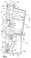
- a lamp-post, road sign, bollard, motorway sign, or other electrically-powered street furniture incorporates a switch unit 1 (shown in Figures 1 and 2) between its power supply and its light.
- the switch unit 1 comprises an isolation switch 2 and a cut-out unit 3.
- the isolation switch 2 has a first, pronged, element 4 and a second, co-operating, L-shaped element 5.
- the element 5 is connected to a power input unit 5a which is fed power via cable 5b.
- the pronged switch element 4 is mounted on a mounting, or sole, plate 6 (comprising a first element) which is movable relative to a housing unit 7 (comprising a second element).
- the sole plate is movable relative to the housing 7 between the open position shown in Figure 1 and a closed position in which the switch element 5 is received between the prongs of the switch element 4 and makes contact with them.
- a cover member 8 is secured (for example by screws) to the sole plate 6 and covers the electrical components of the cut-out unit 3 so as to prevent access to them.
- the cut-out unit 3 has a pair of contact pins 3a which make contact with power input and output terminals 3b and 3c.
- a fuse 3d connects the pins 3a.
- the housing 7 has a top flange 9, a back panel 10, and a base flange 11.
- a spring-biassed plate 12 is provided in the region of the junction of the back panel 10 and base flange 11 and is urged towards restraining lugs 13 by a spring 14.
- the back panel 10, or side panels 15, have projecting lugs 16 provided with pins 17.
- a wall 18 extends away from the back panel 10 and divides the housing 7 into a lower region 19 which has a closure panel 18a to close it off and to prevent access to a chamber 20 by unauthorised personnel, and an upper region 21 in which the cover member 8 is disposed.
- the closed chamber 20 is very useful for "public" supply cut-outs since the electricity board may have their own closure or seals.
- the wall 18 has a slot 22 through which the sole plate 6 extends.
- the back panel 10 has mounting holes 10a.
- the upper region 21 of the housing has a pair of projecting lugs 23 provided with C-shaped slots 24.
- a locating well 25 is provided on the back plate 10.
- the top flange 9 has a first groove 26 which is separated from a second groove 27 by a projecting rib 28, and a third groove 29 disposed towards the furthermost portion of the top flange 9 from the back plate 10.
- the second groove 27 has a notch or recess 30 which is defined in part by a shoulder 31.
- the sole plate 6 has a lower end 32, which rests against the plate 12 and is urged upwards by it, an elongate groove 33 in which the pin 17 is received, and pins 34 received in the C-shaped slots 24 of the lugs 25.
- a biassing member 35 has one end received in the groove 26 and its other end lodged in a notch defined between the sole plate 6 and a projection 36 extending away from the sole plate.
- the biassing member 35 has a locating well 37.
- a spring 38 is received in the two wells 25 and 37 and urges the lower end of the biassing member 35 away from the back panel 10.
- the cover member 8 is held to the sole plate 6 by externally accessible screws (not shown). In the open configuration shown in Figure 1, the screws which hold the cover member 8 to the sole plate 6 can be unscrewed and the cover 8 can be removed to allow access to the cut-out unit 3. It will be noted that the isolation switch 2 is in its open configuration. It will also be noted that an upwardly-directed flange 39 of the cover member is not located by part of the housing when the switch is in its open configuration.
- the user then moves, or allows to be moved, the plate 6 upwards, so that the pin 34 is received at the top end of the vertical portion of the slot 24, which is nearest to the back panel 10, and so that the top end of the sole plate 6 is received in the groove or channel 27, with the flange 39 of the cover member being received in the notch 30.
- the shoulder 31 then overlays a portion of the flange 39 and the cover member cannot be removed from the sole plate, even when its securing screws are removed.
- the pronged switch element 4 associated with the sole plate moves first of all downwardly in the direction of arrow A to a position in which the top edge of the prongs is below the bottom edge of the L-shaped switch element 5, then as the sole plate 6 is pivoted towards the back panel 10 the prongs of the switch element 4 move to a position in which they are beneath the switch element 5, then as the sole plate 6 rises upwards the switch element 5 is received between the prongs of the switch element 4.
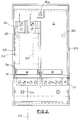
- Figure 2 shows that the switch 1 has two power output terminals 3c, and two cartridge fuses 3d, and so can supply power to two electrically-powered devices. If the power input terminal 3b were split into two on line 40 the switch could be used to loop a supply line.
- the switch 1 has double pole isolation: it isolates the live and neutral terminals from the supply.
- the housing unit 7 may include PME (Protective Multiple Earthing), whether switched or unswitched, and has an additional earth terminal 41 in the closed chamber 20.
- the housing can also accept a miniature circuit breaker instead of the fuses 3d. By changing the block of terminals in the chamber 20 the switch can be converted from barrel-type to lug-type terminals.
- the switch Since the switch is double pole isolating we arrange for there to be a lead lag on the neutral pin of the cut-out.
- the neutral pin is the last contact to break and the first contact to make. This avoids capacitance build-up during making/breaking of the circuit and reduces arcing.
- FIGs 3 to 6 show details of a cover member/housing interlock safety mechanism 50 (schematically shown on Figure 1).
- the interlock mechanism 50 prevents movement of the sole plate 6, and the switch 2, back towards the closed position when the cover member is not mounted on the sole plate.
- the cover member 8 is integrally moulded in plastics materials and has side walls 51 provided with a lip 52 and, at an interlock region, with a camming finger 52 provided with a cam surface 53.
- the side surfaces of the sole plate 6 are provided with a pair of notches 54 and an abutment region 55.
- the housing 7 has side walls 56 provided at an interlock region with an internal flange 57 connected to the wall 56 by a connection portion 58.
- the flange 57 has in a longitudinally arranged sequence a first cam portion 59, an abutment portion 60, and a second cam portion 61.
- the abutment portion 60 has an obstructing face 62 and comprises a stepped region of the continuous flange 57.
- the cam portions 59 and 61 have cam surfaces 63 which face the cam surfaces 53 of the fingers 52. Springs 64 urge the cam portions 59 and 61 away from the wall 56.
- Figure 3 shows the interlock mechanism in its obstructing configuration, with the sole plate in its open position.
- the sole plate 6 cannot move in the direction of arrow C because its abutment region 55 engages against the obstructing face 62 which prevents movement towards the back panel 21.
- the switch 2 therefore cannot be closed. Pushing the sole plate 6 without the cover member 8 in place is no help.
- the cover member is needed for the switch to be closed.
- the interlock is between part of the cover moulding and the housing, not any separate, loose, component of either which could become lost or mis-orientated.
- the switch 1 shown in Figures 1 and 2 pivots towards the bottom of the sole plate, but we could arrange for the pivoting to occur at some other place, for example above the isolation switch 2.
- the pivoting may occur in the upper region of the housing.
- a leaf spring may be provided between the back panel and the sole plate.
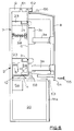
- the flange 9 has two transversely-spaced grooves 61 and 62 which receive the sole plate 6 in its closed and open positions respectively. There are two pairs of projecting lugs 23 with guide slots 24.
- the wall 18a has a notch 63 adapted to receive a bottom lip 64 of the cover member 8 when the cover member is in its closed position.
- the cover member is screwed to the housing 7 in the region of the lip 64 by screws 65.
- the top wall of the cover member has a projecting rib 66 which is received in groove 62 when the cover member is in its closed position.
- FIG 7 shows yet another switch which is similar in many ways to that of Figure 6. Similar components have been given the same reference numerals.
- the switch comprises a two unit device comprising a switch unit 70a and a power supply unit 70b.
- the chamber 20 is defined by a separate self-contained box 70 which can be removed from the switch.
- the box 70 has a removable cover 71 (which may need special tools to remove it), a gland plate 72, and a main electrical terminal block 5a.
- the block 5a has female electrical connectors 73 which releasably co-operate with male electrical connectors 74 provided associated with the switch unit 70a.
- the connectors 74 are electrically connected to the prong 5.
- cover member itself is the part of the switch which the user moves to operate the switch.
- the interlock is provided by way of buttons 80 below the sole plate (not shown).
- the cover 81 is provided with extended pins.
- the cover is located in an open position over the housing unit by means of co-operating tabs 82, 83 on the cover 81 and housing unit 84.
- This embodiment may conveniently be used with a separate terminal block, as discussed in relation to the embodiment of Figure 7.
- the load carrying cable entries are at at least 30° to the horizontal to prevent condensation travelling along the cable into the fuse unit.
- the unit incorporates a facility whereby the electricity supply companies incoming feed cables can be sealed and identified and the fuse switching unit can be demountable from the supply companies termination.
- the unit may have triangular three point fixings external to current carrying cavities.
- the function of all terminals is clearly indicated by permanent means.
- a cable termination box or cover may be available for the protection of incoming cables. It may be an integral part of the unit or it may interlock into the base of the unit so that the box or cover cannot be removed until the isolation switch is in the "off" position.
- the box or cover may have a split gland plate to accommodate the incoming service supply cable and the loop feed cable to enable work to occur on one without disruption to the other.
- the unit may be manufactured from a high impact resistant non-hydroscopic material, preferably ABS flame retardant or similar.
- terminal shrouds are to be incorporated within the unit.
- the means provided for clamping the fuse link do not interfere with the requirement that constant pressure is to be maintained between the fused contacts and fixed terminals. Undue force is not required to withdraw the fuse carriers from the bases.
- the fuse carriers can accommodate an outgoing fused loop supply from the lower terminal chamber, or two fused outgoing terminals.
- All outgoing load terminals are fixed, and the unit accommodates an internal earth terminal for outgoing earth connections.
- the unit may also have facilities for commissioning, and performing operational and maintenance testing which allows all the relevant tests to be executed without disconnection of outgoing or incoming cables. If necessary, the unit may also facilitate visual indication of the status of the incoming supply and/or the integrity of the fuse.
- isolation switch/protection unit All of the component parts of the isolation switch/protection unit maybe fully interchangeable, and further may be interchangeable without disruption to the supply authorities' incoming terminations.
Landscapes
- Engineering & Computer Science (AREA)
- Power Engineering (AREA)
- Switch Cases, Indication, And Locking (AREA)
- Push-Button Switches (AREA)
Applications Claiming Priority (4)
| Application Number | Priority Date | Filing Date | Title |
|---|---|---|---|
| GB9123073 | 1991-10-30 | ||
| GB919123073A GB9123073D0 (en) | 1991-10-30 | 1991-10-30 | Switches |
| GB929202857A GB9202857D0 (en) | 1991-10-30 | 1992-02-11 | Switches |
| GB9202857 | 1992-02-11 |
Publications (1)
| Publication Number | Publication Date |
|---|---|
| EP0540327A1 true EP0540327A1 (fr) | 1993-05-05 |
Family
ID=26299774
Family Applications (1)
| Application Number | Title | Priority Date | Filing Date |
|---|---|---|---|
| EP92309909A Withdrawn EP0540327A1 (fr) | 1991-10-30 | 1992-10-29 | Coupe-circuit à sectionneur |
Country Status (2)
| Country | Link |
|---|---|
| EP (1) | EP0540327A1 (fr) |
| GB (1) | GB2261116B (fr) |
Families Citing this family (4)
| Publication number | Priority date | Publication date | Assignee | Title |
|---|---|---|---|---|
| GB2304420B (en) * | 1993-02-16 | 1997-09-17 | Raymond Mew | Improvements in and relating to switches |
| GB9303026D0 (en) * | 1993-02-16 | 1993-03-31 | Mew Raymond | Improvements in and relating to switches |
| GB9624912D0 (en) * | 1996-11-29 | 1997-01-15 | Electrical Testing Limited | Power cut-out safety device |
| GB2345998A (en) | 1999-01-20 | 2000-07-26 | Raymond Mew | Remote monitoring and signalling, especially in tunnels |
Citations (4)
| Publication number | Priority date | Publication date | Assignee | Title |
|---|---|---|---|---|
| GB1170936A (en) * | 1966-12-06 | 1969-11-19 | English Electric Co Ltd | Improvements in Fuse Fittings. |
| DE8601549U1 (de) * | 1985-01-22 | 1986-03-27 | Cambridge Electronic Industries p.l.c., Cambridge | Sicherungshalter |
| EP0400860A1 (fr) * | 1989-05-31 | 1990-12-05 | Hawker Fusegear Limited | Support de coupe-circuit fusible |
| DE9202133U1 (de) * | 1992-02-19 | 1992-04-23 | Albrecht Jung GmbH & Co KG, 7965 Ostrach | Berührungsschutz für NH-Sicherungslasttrennschalter |
Family Cites Families (14)
| Publication number | Priority date | Publication date | Assignee | Title |
|---|---|---|---|---|
| GB243452A (en) * | 1924-08-30 | 1925-11-30 | Reyrolle A & Co Ltd | Improvements in or relating to oil-immersed electric switches |
| GB286943A (en) * | 1927-06-22 | 1928-03-15 | James Brown | Improved fuse cut out for electric circuits |
| GB342418A (en) * | 1929-11-20 | 1931-02-05 | Albert Rudman | Improvements in or relating to circuit interrupters |
| GB351597A (en) * | 1930-04-04 | 1931-07-02 | Joseph Sachs | Improvements in or relating to electric switches |
| GB382701A (en) * | 1931-09-01 | 1932-11-03 | Reginald Thomas Norton | Improvements in and relating to electrical oil switch fuses |
| GB421416A (en) * | 1933-06-19 | 1934-12-19 | Weekes Luton Ltd L | Improvements in and relating to electric switch fuses |
| GB442960A (en) * | 1934-11-17 | 1936-02-19 | Ellison George Ltd | Improvements relating to electric switch gear |
| FR874097A (fr) * | 1939-01-25 | 1942-07-28 | Interaero Ind Handel Sondernem | Commutateur électrique |
| GB528717A (en) * | 1939-05-13 | 1940-11-05 | John Michael Hollander | Improvements relating to electric distribution apparatus |
| GB664073A (en) * | 1949-04-05 | 1952-01-02 | Harold Cyril Cooper | Improvements in or relating to electric isolating switches for use in electric circuits embodying fuses |
| GB879669A (en) * | 1958-06-07 | 1961-10-11 | Bassani Spa | Improvements in or relating to electric switches |
| GB1139696A (en) * | 1966-08-23 | 1969-01-08 | Amp Inc | Improvements in fused switches |
| US4400678A (en) * | 1981-04-29 | 1983-08-23 | Chen Chang C | Fuse switch box |
| US4755909A (en) * | 1987-03-16 | 1988-07-05 | General Electric Company | Fused disconnect switch with non-metallic enclosure |
-
1992
- 1992-10-29 GB GB9222718A patent/GB2261116B/en not_active Expired - Fee Related
- 1992-10-29 EP EP92309909A patent/EP0540327A1/fr not_active Withdrawn
Patent Citations (4)
| Publication number | Priority date | Publication date | Assignee | Title |
|---|---|---|---|---|
| GB1170936A (en) * | 1966-12-06 | 1969-11-19 | English Electric Co Ltd | Improvements in Fuse Fittings. |
| DE8601549U1 (de) * | 1985-01-22 | 1986-03-27 | Cambridge Electronic Industries p.l.c., Cambridge | Sicherungshalter |
| EP0400860A1 (fr) * | 1989-05-31 | 1990-12-05 | Hawker Fusegear Limited | Support de coupe-circuit fusible |
| DE9202133U1 (de) * | 1992-02-19 | 1992-04-23 | Albrecht Jung GmbH & Co KG, 7965 Ostrach | Berührungsschutz für NH-Sicherungslasttrennschalter |
Also Published As
| Publication number | Publication date |
|---|---|
| GB9222718D0 (en) | 1992-12-09 |
| GB2261116A (en) | 1993-05-05 |
| GB2261116B (en) | 1995-07-12 |
Similar Documents
| Publication | Publication Date | Title |
|---|---|---|
| US6864443B1 (en) | Multipolar circuit-protection assembly for a collector rail system | |
| CN101124647B (zh) | 可熔的开关断开模块和设备 | |
| CN112531386B (zh) | 电插座以及用于电插座的防误触盒 | |
| US5393942A (en) | Panelboard having panel-mounted interlock for two main circuit breakers | |
| SK278330B6 (en) | Protection equipment of switching apparatus | |
| US20110176258A1 (en) | Configurable deadfront fusible panelboard | |
| US5274527A (en) | Housing with plug-in connections | |
| CA2829851C (fr) | Couvercle souple pour contacts d'un module d'extension ou d'une unite amovible | |
| US7586052B2 (en) | Electromechanical switching device | |
| US5060107A (en) | Molded case circuit breaker operating handle guard | |
| US5936214A (en) | Apparatus for restricting operation of push buttons on electric switching apparatus | |
| EP0540327A1 (fr) | Coupe-circuit à sectionneur | |
| EP0788205A2 (fr) | Améliorations aux équipements de distribution électrique | |
| US4491897A (en) | Plug-in base for low-voltage circuit breakers | |
| CN1055776C (zh) | 用于高安培断路器的二次断接组件 | |
| EP0605545A1 (fr) | Appareil electrique verrouillable | |
| GB2310768A (en) | Distribution equipment for a wall mountable consumer unit | |
| US4534612A (en) | Current connecting device for the establishing of electrical connection between conductors | |
| EP3149818A1 (fr) | Ensemble pour dispositif de commutation amovible et dispositif de commutation associé | |
| EP0612131A2 (fr) | Améliorations relatives aux interrupteurs | |
| EP0220249B1 (fr) | Dispositif de securite pour commutateurs | |
| GB2275137A (en) | Supply unit and switch for street furniture | |
| AU2010236024B2 (en) | Safety device for electrical distribution board | |
| JPH06176810A (ja) | 端子台 | |
| GB2117178A (en) | Switch-fuse unit |
Legal Events
| Date | Code | Title | Description |
|---|---|---|---|
| PUAI | Public reference made under article 153(3) epc to a published international application that has entered the european phase |
Free format text: ORIGINAL CODE: 0009012 |
|
| AK | Designated contracting states |
Kind code of ref document: A1 Designated state(s): BE DE FR GB IE NL |
|
| 17P | Request for examination filed |
Effective date: 19931029 |
|
| 17Q | First examination report despatched |
Effective date: 19950425 |
|
| GRAH | Despatch of communication of intention to grant a patent |
Free format text: ORIGINAL CODE: EPIDOS IGRA |
|
| RBV | Designated contracting states (corrected) |
Designated state(s): BE DE FR IE NL |
|
| 18D | Application deemed to be withdrawn |
Effective date: 19961029 |